BDN9 Rev. 3
Parts List
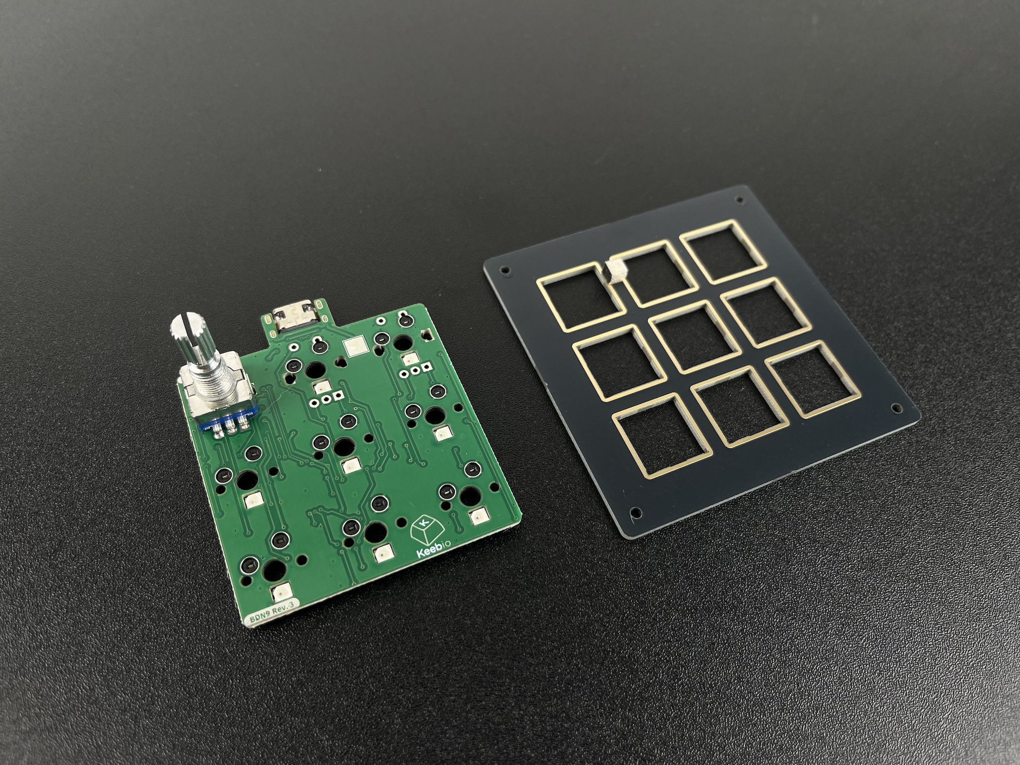
Here's a list of parts needed for the build:
- 1 BDN9 Rev. 3 PCB & Bottom PCB Plate with M2 screws and standoffs
- 6-9 MX-compatible switches
- Up to 3 EC11 or EC12 Rotary Encoders (optional)
Build Steps
Here's a summary of the build steps:
- Prepare components
- Solder rotary encoders
- Add switches
- Assemble case
Prepare components
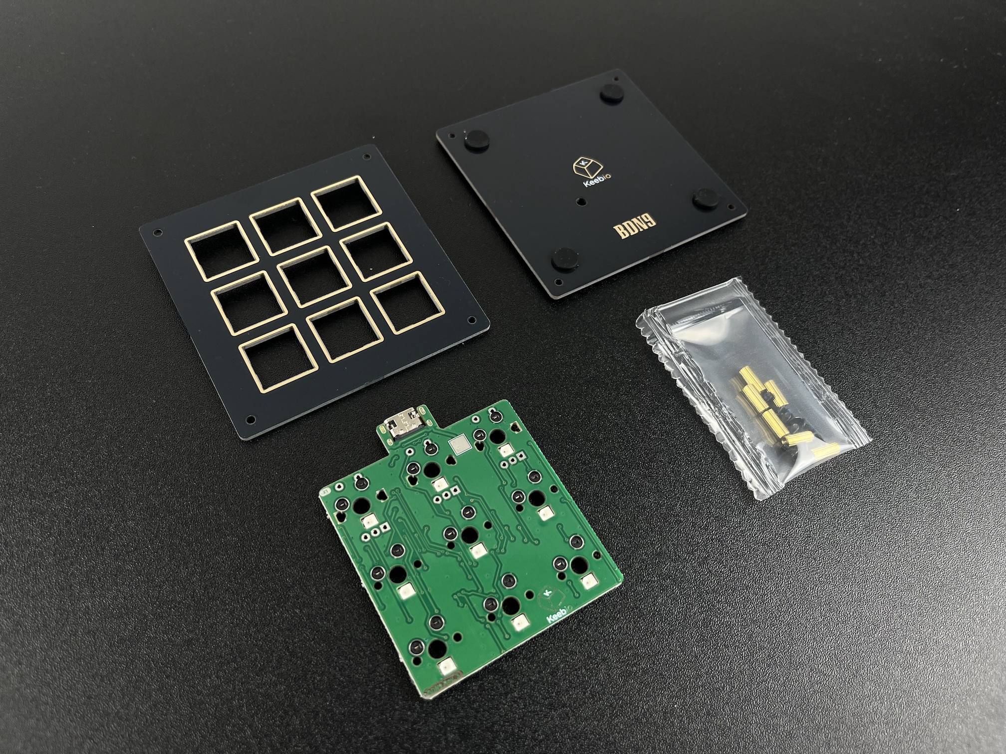
Parts from the kit.
Solder Rotary Encoders
It is difficult to put in the rotary encoders into the PCB pads if the switch plate and switches are already on, so make sure you add the encoders first.
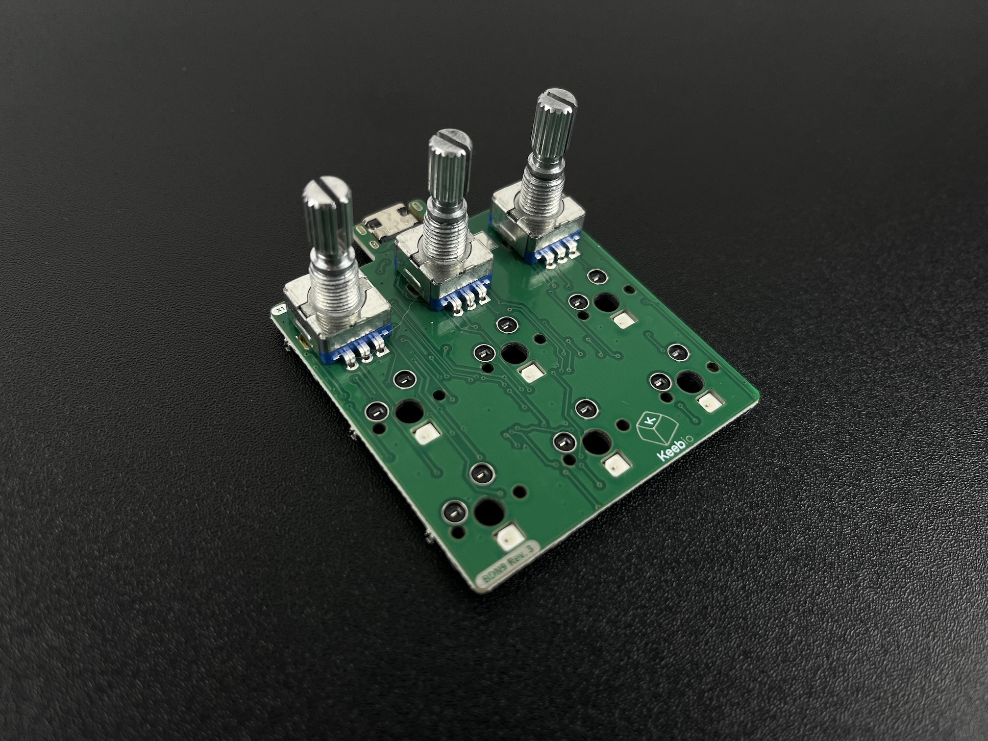
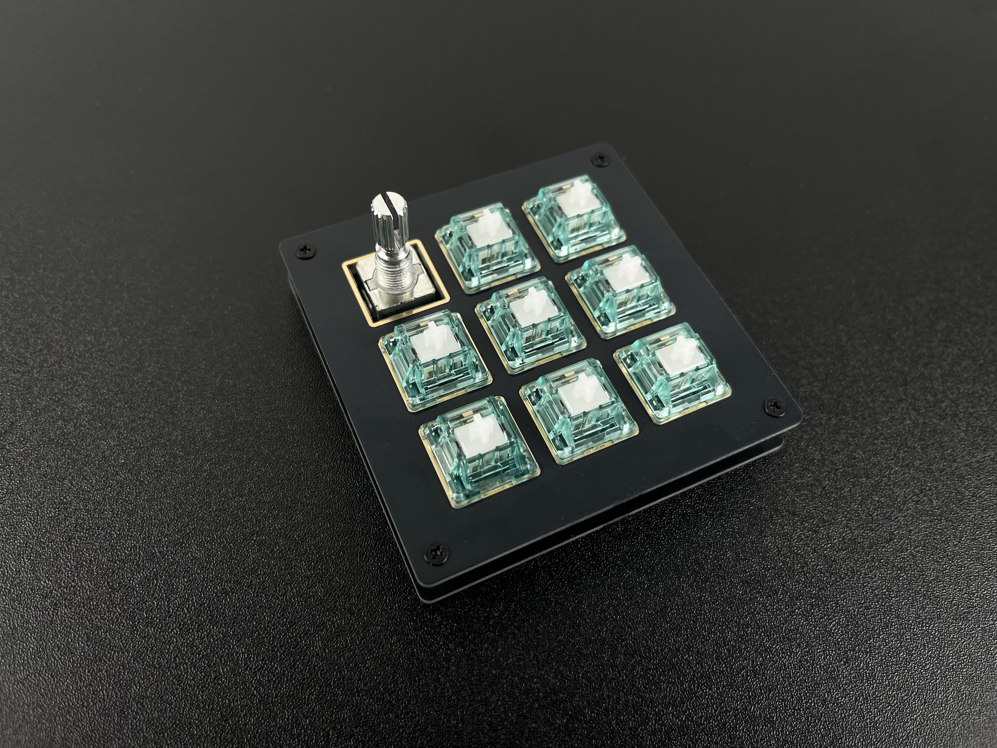
Insert the rotary encoders from the top-side of the PCB.
Solder the rotary encoders in.
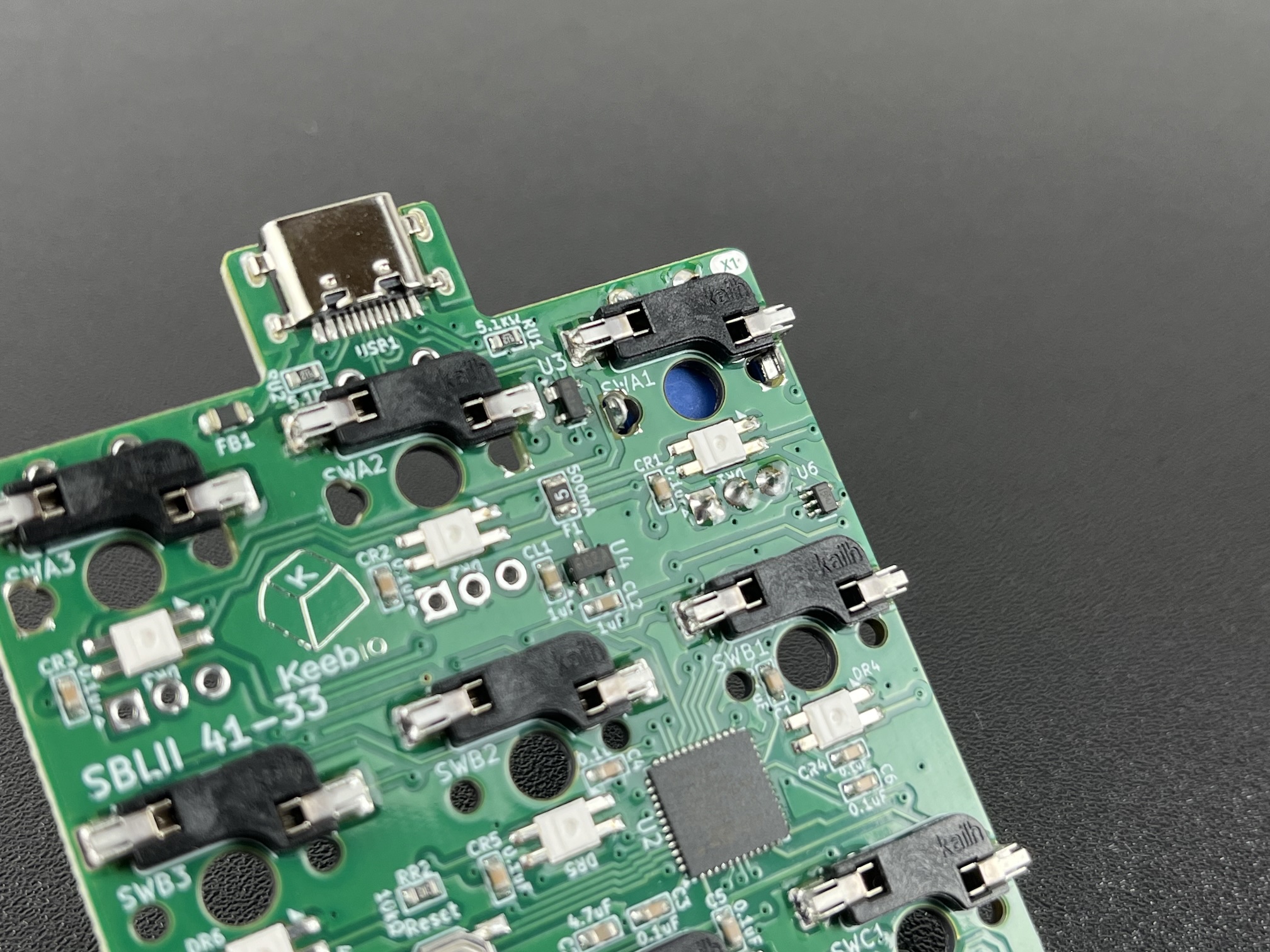
Add Switches
First, make sure the ESD pad is on the underside of the switch plate and that the plate is oriented with the pad towards the top of the board.
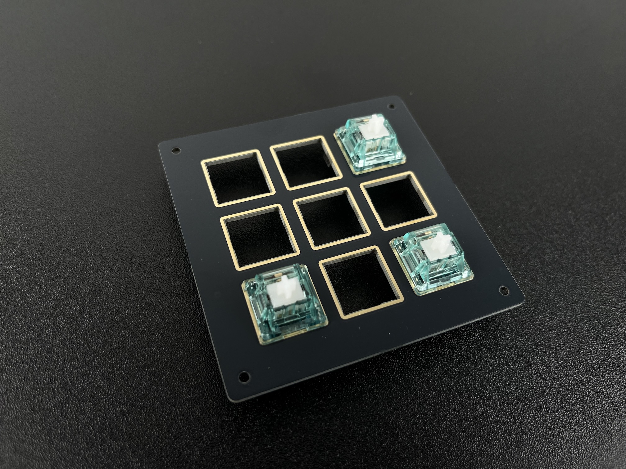
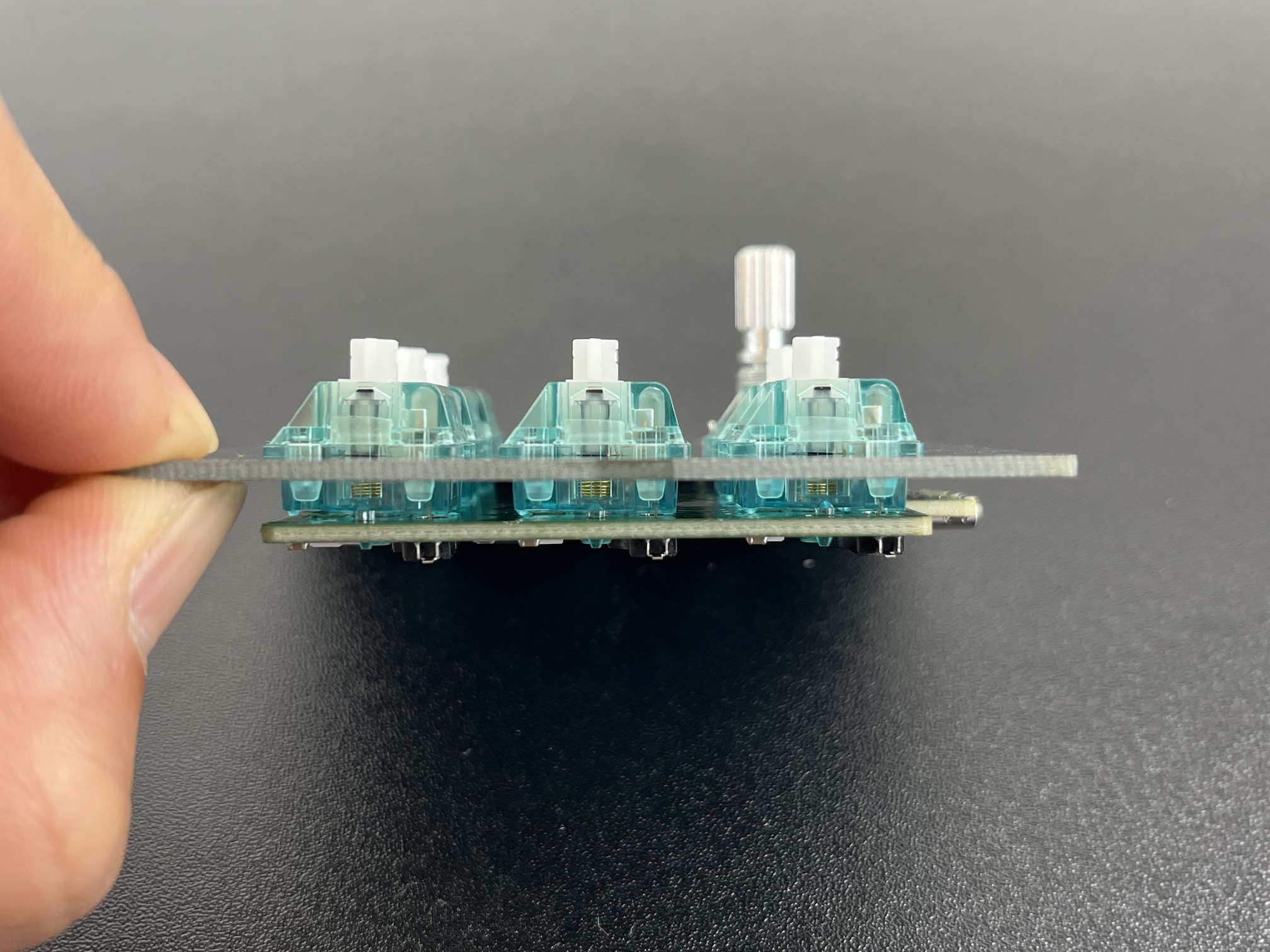
Insert the switches into the switch plate at the corners.
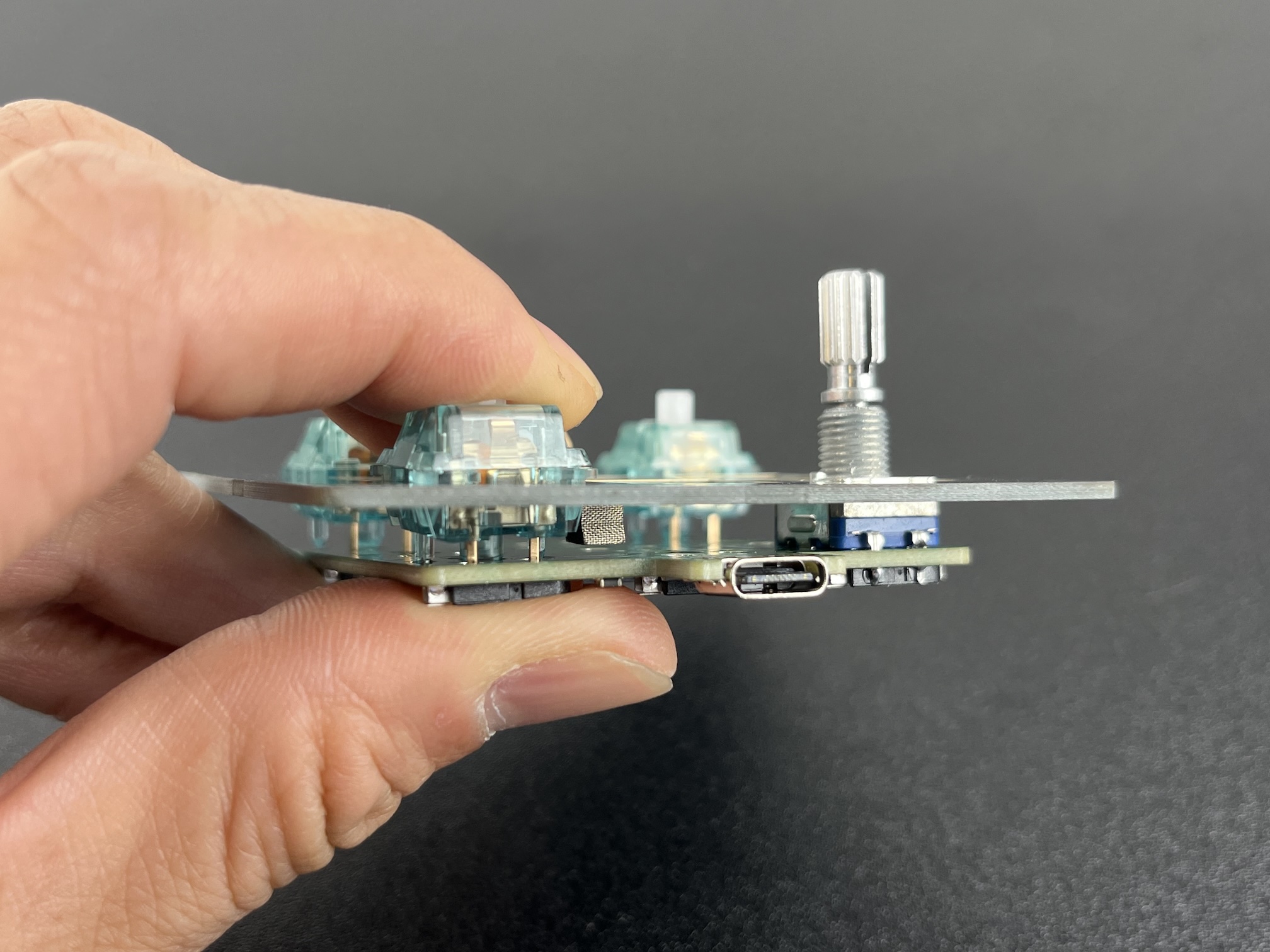
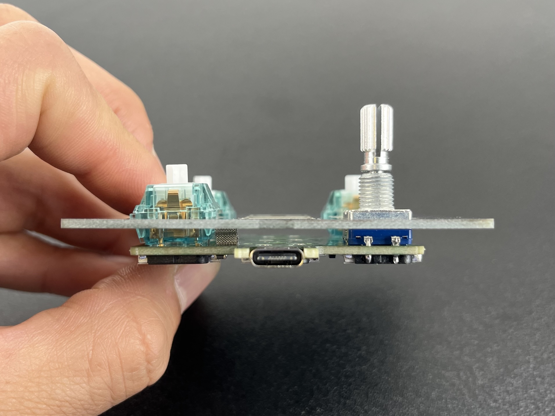
Press down on the switches while supporting the hotswap socket with your thumb from below to prevent socket from separating from the PCB.
Insert the rest of the switches into the plate and PCB.
Assemble Case
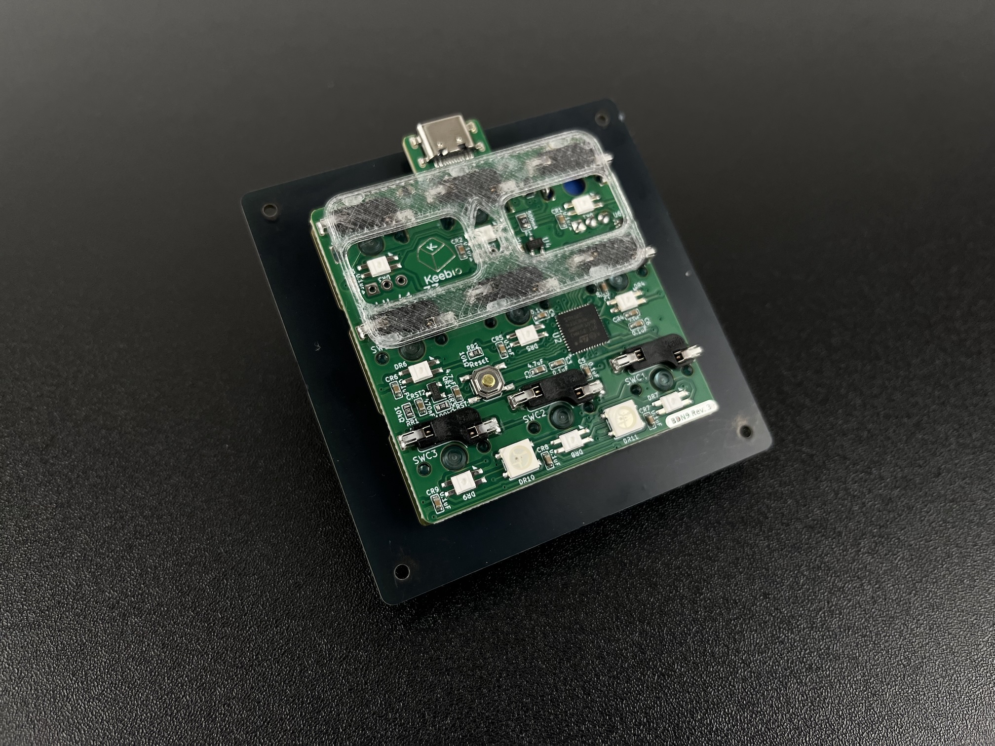
If you soldered on encoders earlier, you'll need to place the included 3D-printed support piece over the hotswap sockets as shown below. This will allow you to press down on the encoders without causing the switches to dislodge from the PCB.
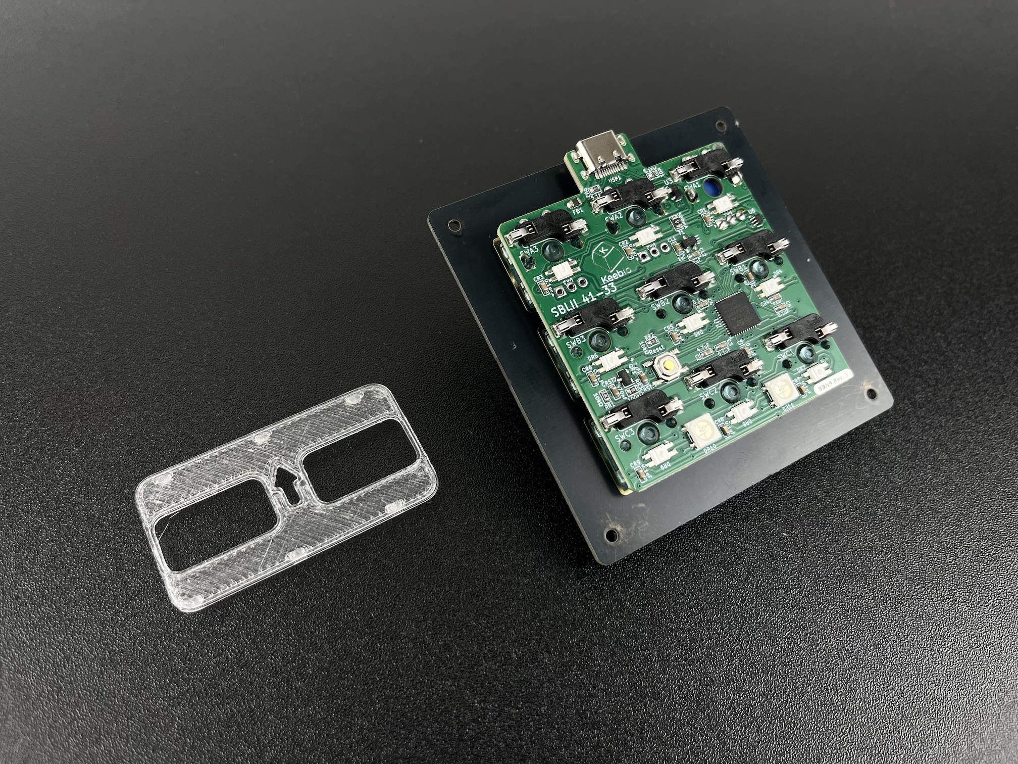
Place the support piece over the hotswap sockets with the arrow facing upwards
Screw in the standoffs to the bottom plate at all four corners.
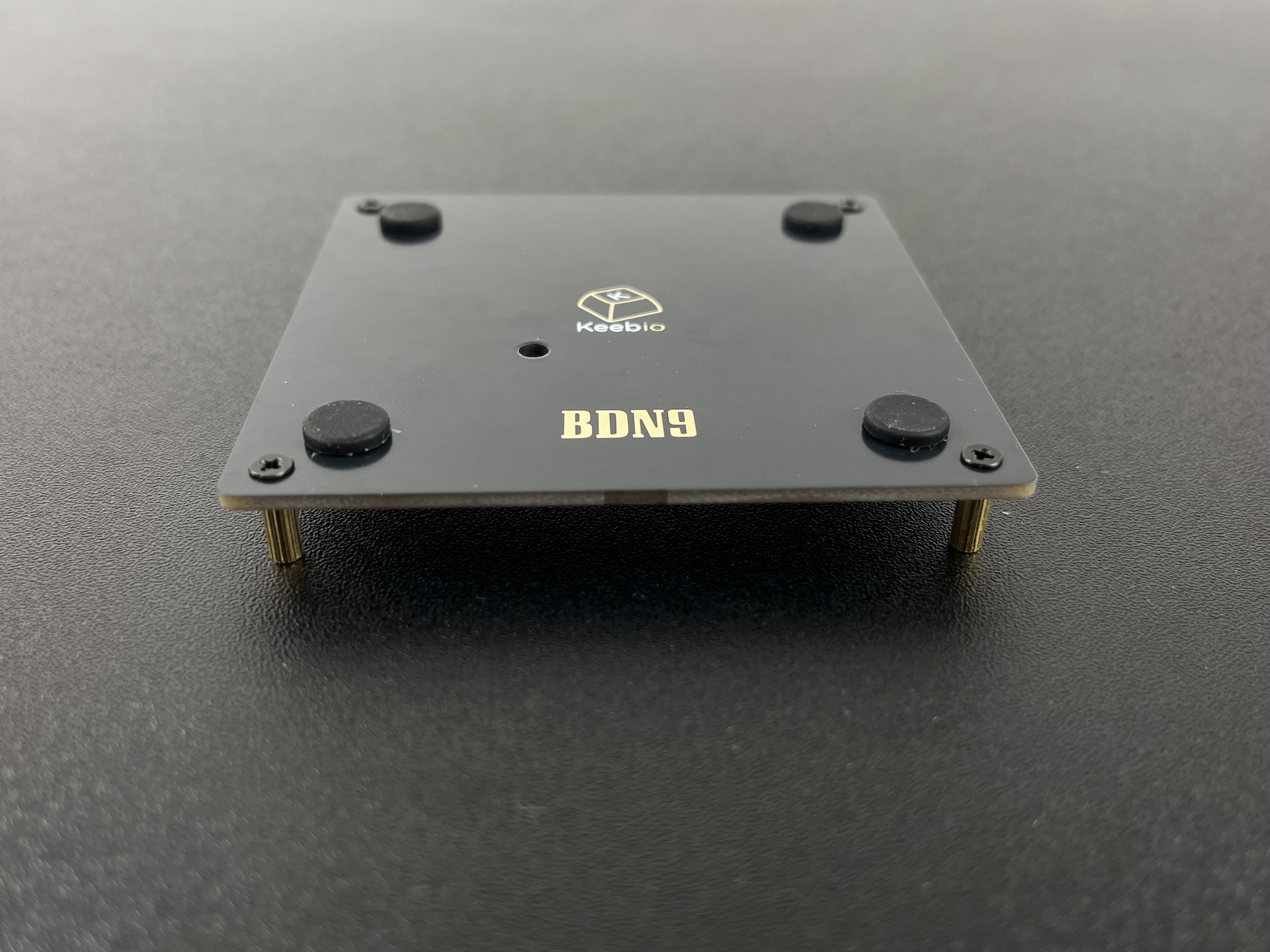
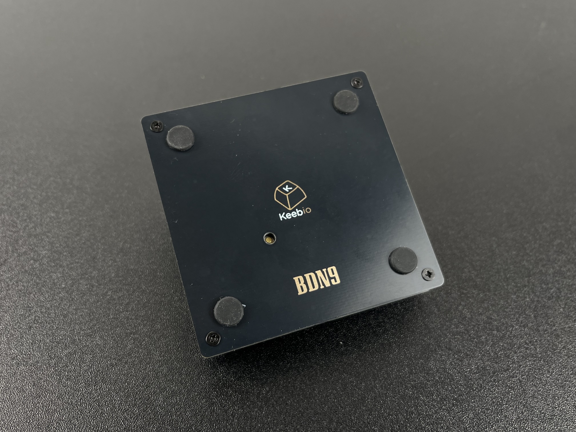
Line up the bottom plate with the rest of the board. The reset button on the PCB should be aligned with the reset hole on the bottom plate.
Add screws though the switch plate and screw it in to the bottom part of the case.
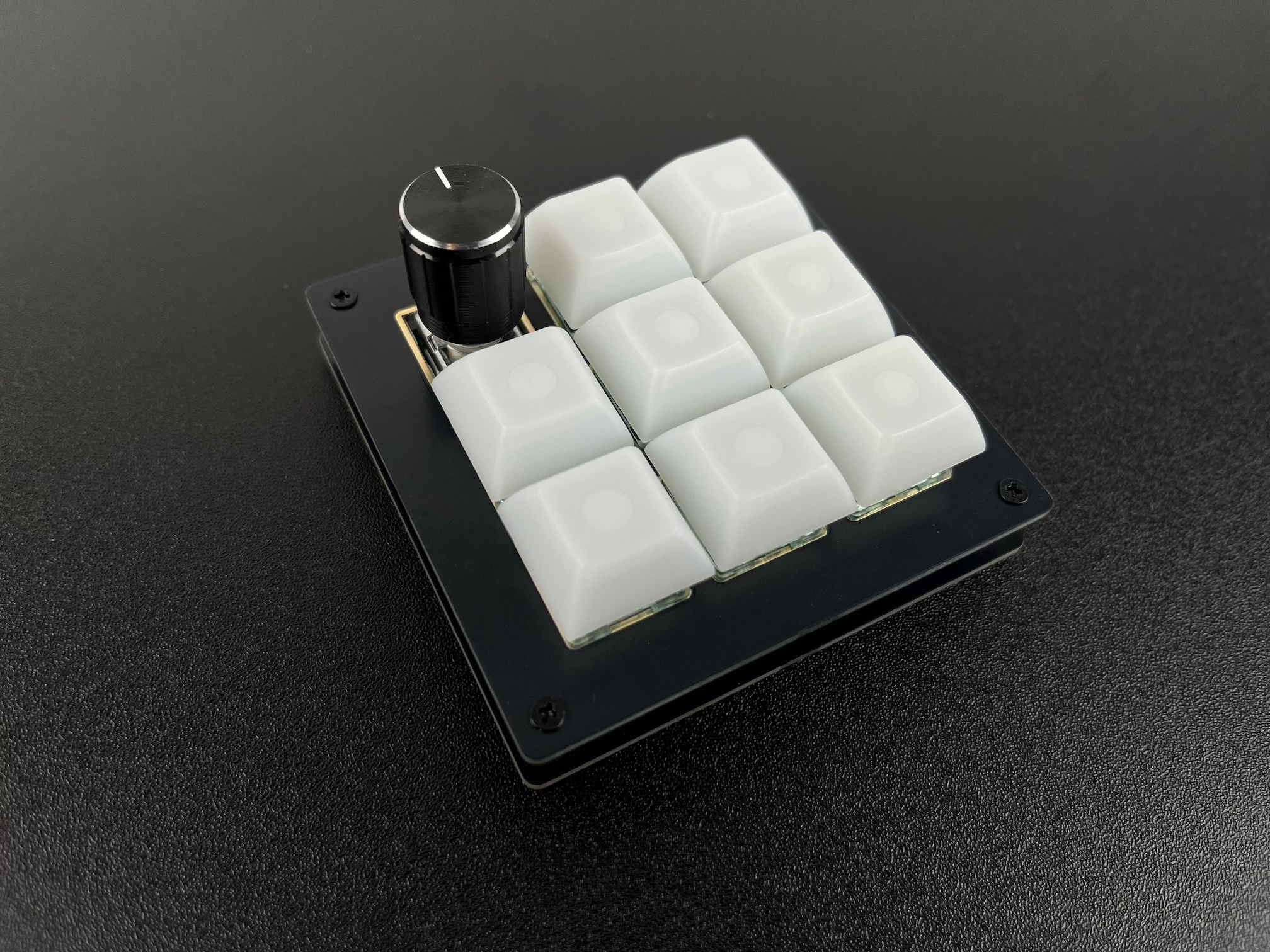
Add keycaps to the switches.
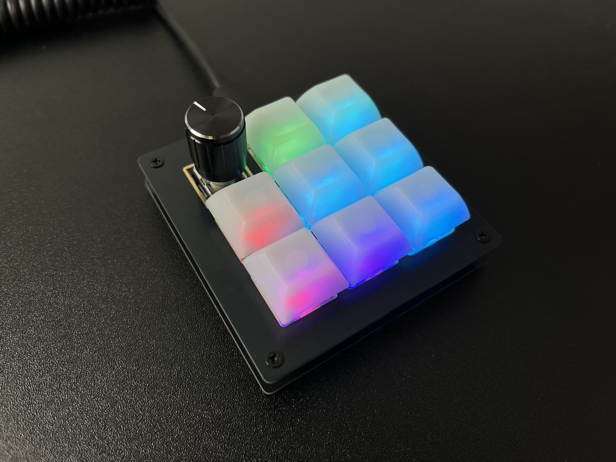
Plug it in and test. For the RGB underglow, the mode is controlled by the right-most key in the middle row in the default layout. If the RGB LEDs don't light up, check your wiring or make sure the pads have enough solder.