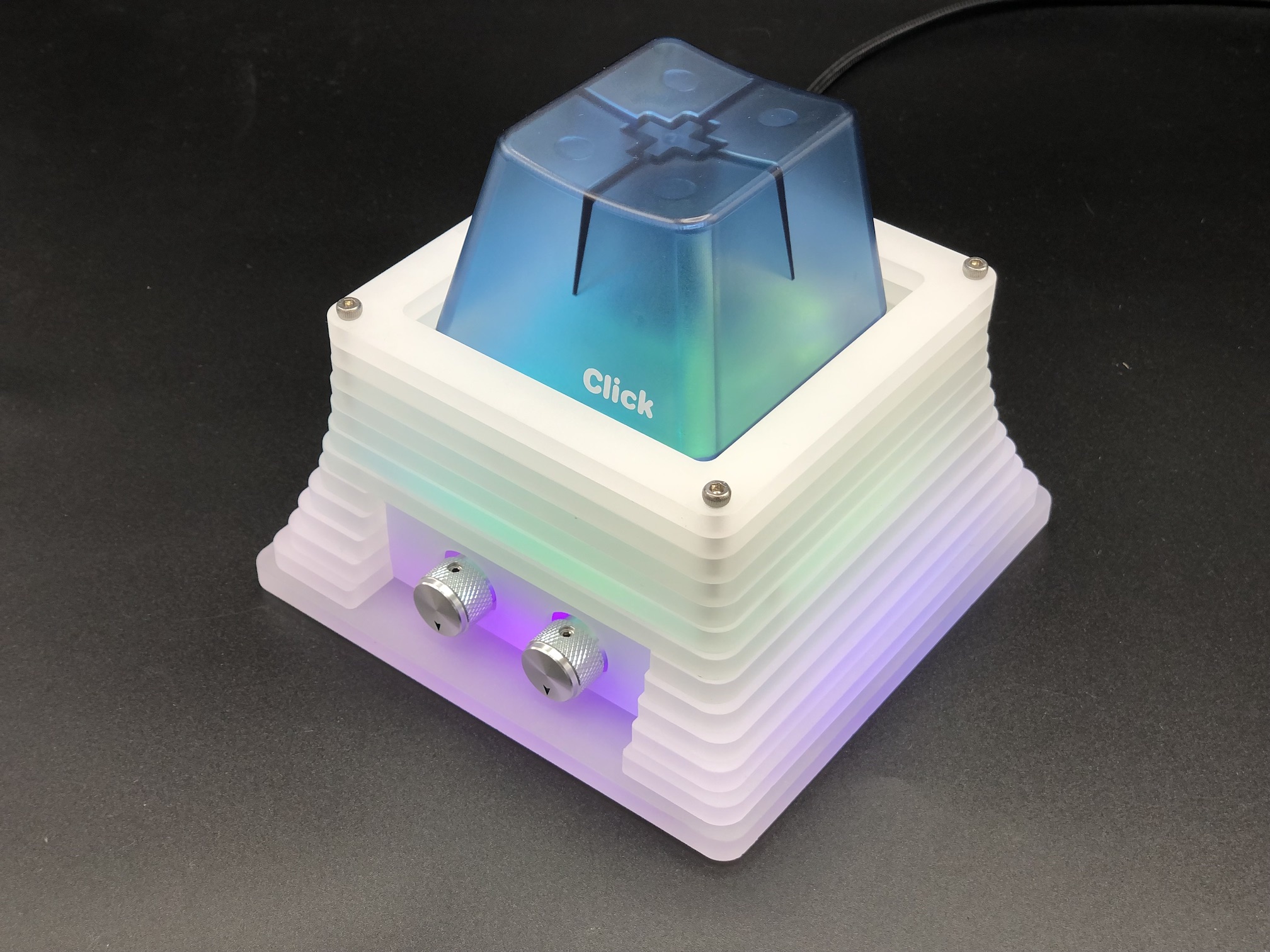
BAMFK-1 Build Guide
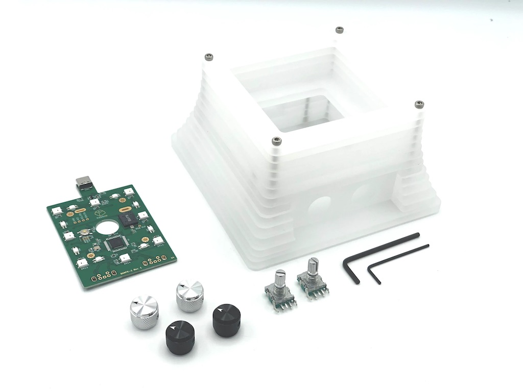
Parts List
- Big Switch
- BAMFK-1 Acrylic Case
- Note: If you've purchased this kit, you will have the rest of the parts below
- BAMFK-1 PCB
- EC11B Horizontal Encoders
- Encoder Knobs
- 1.5mm and 2.5mm Hex Keys
- M3 screws and rivet nuts
Video Tutorial
Build Steps Summary
- Remove top half of case
- Insert switch into plate
- Solder encoders
- Install knobs
- Solder Big Switch
- Insert plate into case
- Reassemble top half of case
Remove Top Half of Case
If your case has been fully disassembled, you'll need to reassemble the bottom portion of the case first. See the steps for making the bottom half first before following the rest of these steps.
Unscrew the screws at the top of the case and remove the top 5 layers and switch plate. Don't unscrew the bottom portion of the case and leave it as is.
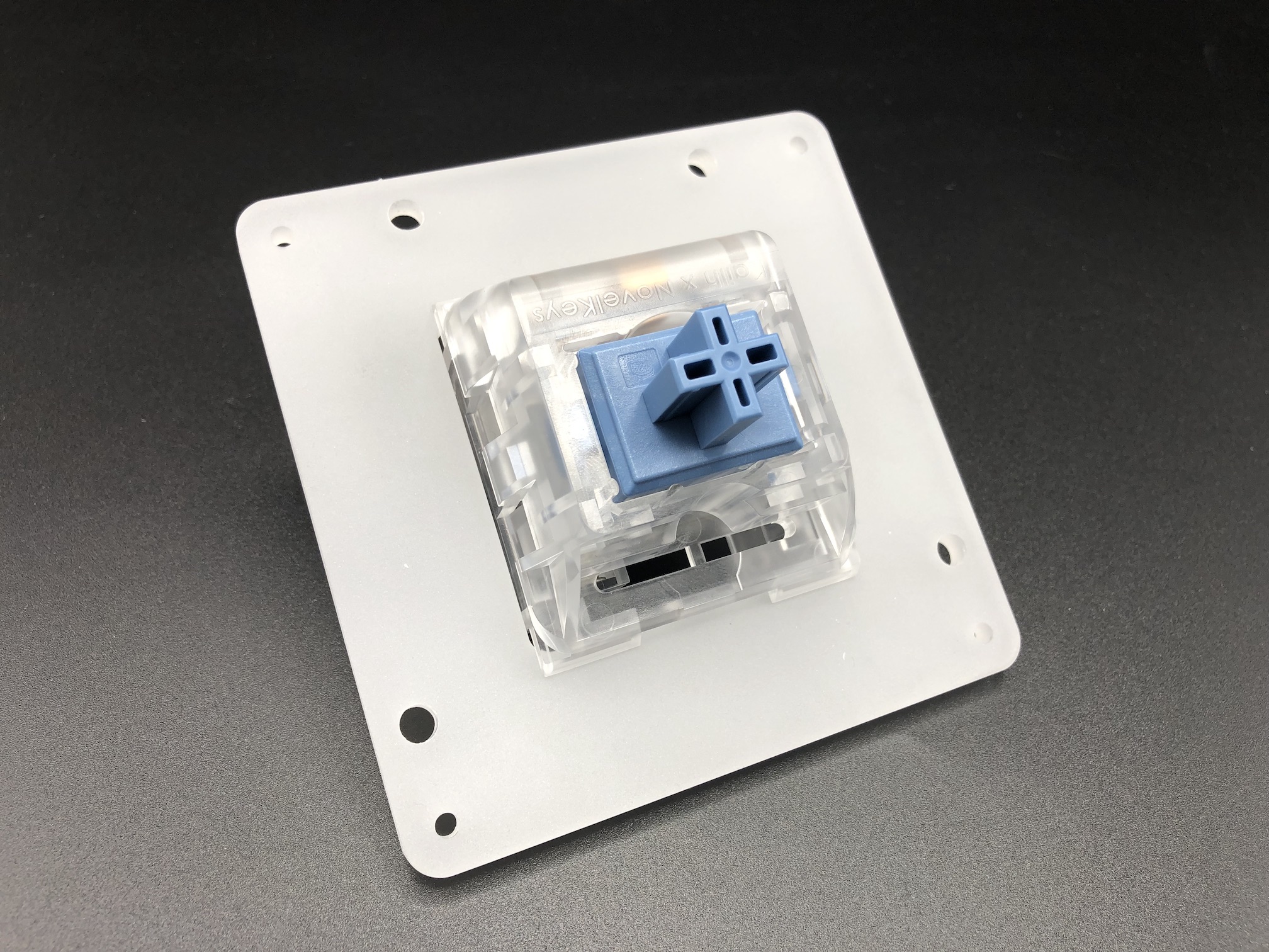
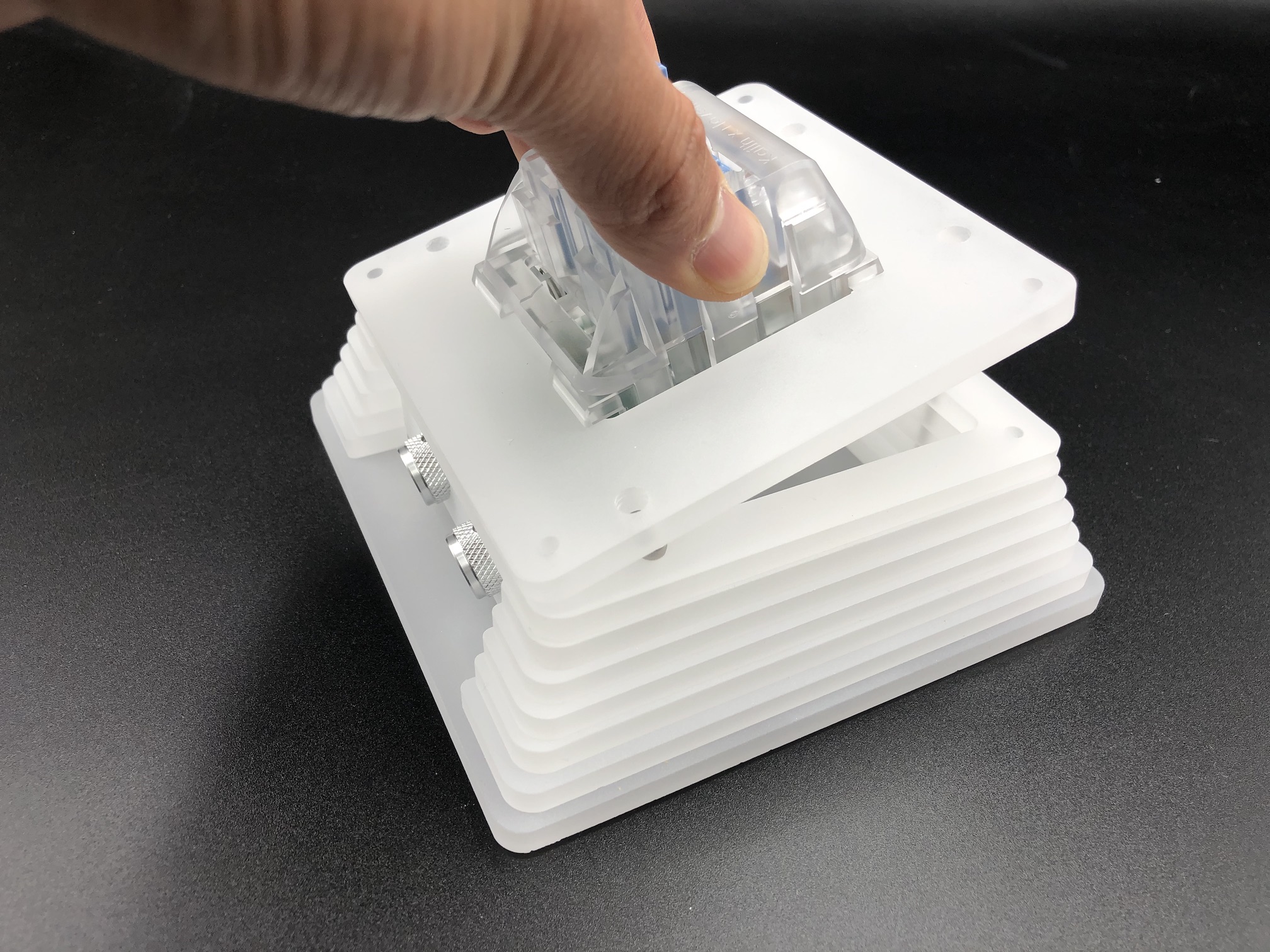
Insert Switch into Plate
Insert the Big Switch into the switch plate, making sure the holes are in the correct orientation as shown below.
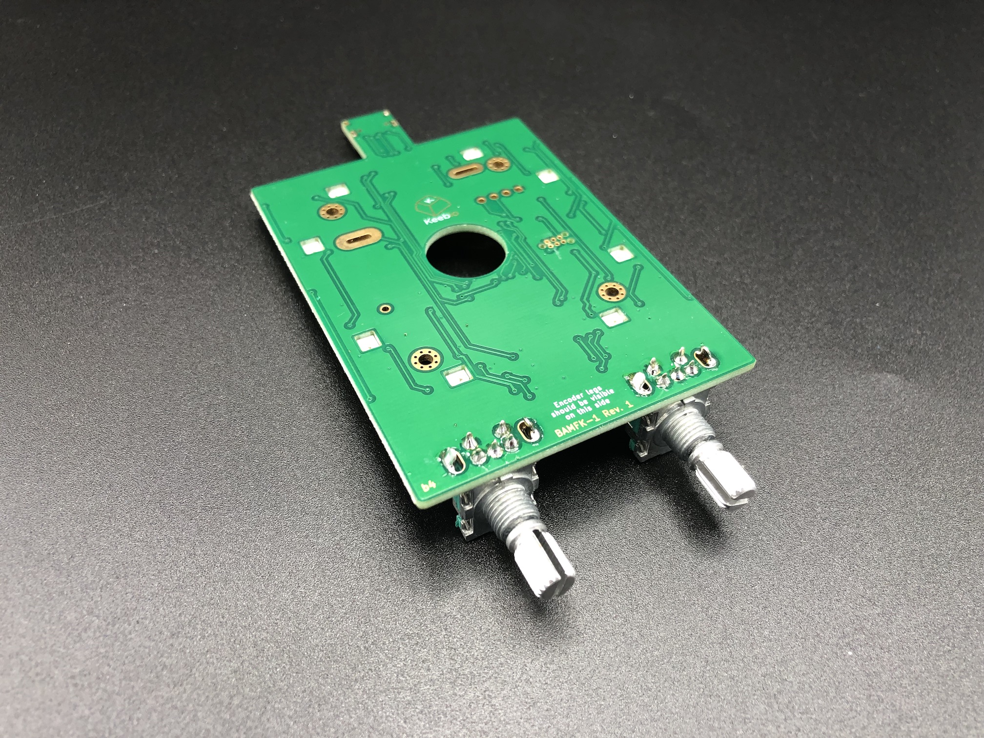
Solder Encoders
Add the rotary encoders to the PCB and solder them in.
Make sure you insert the encoders from the bottom side of the PCB and solder them in place on the top side. You may have a hard time desoldering the encoders if you insert them on the wrong side.
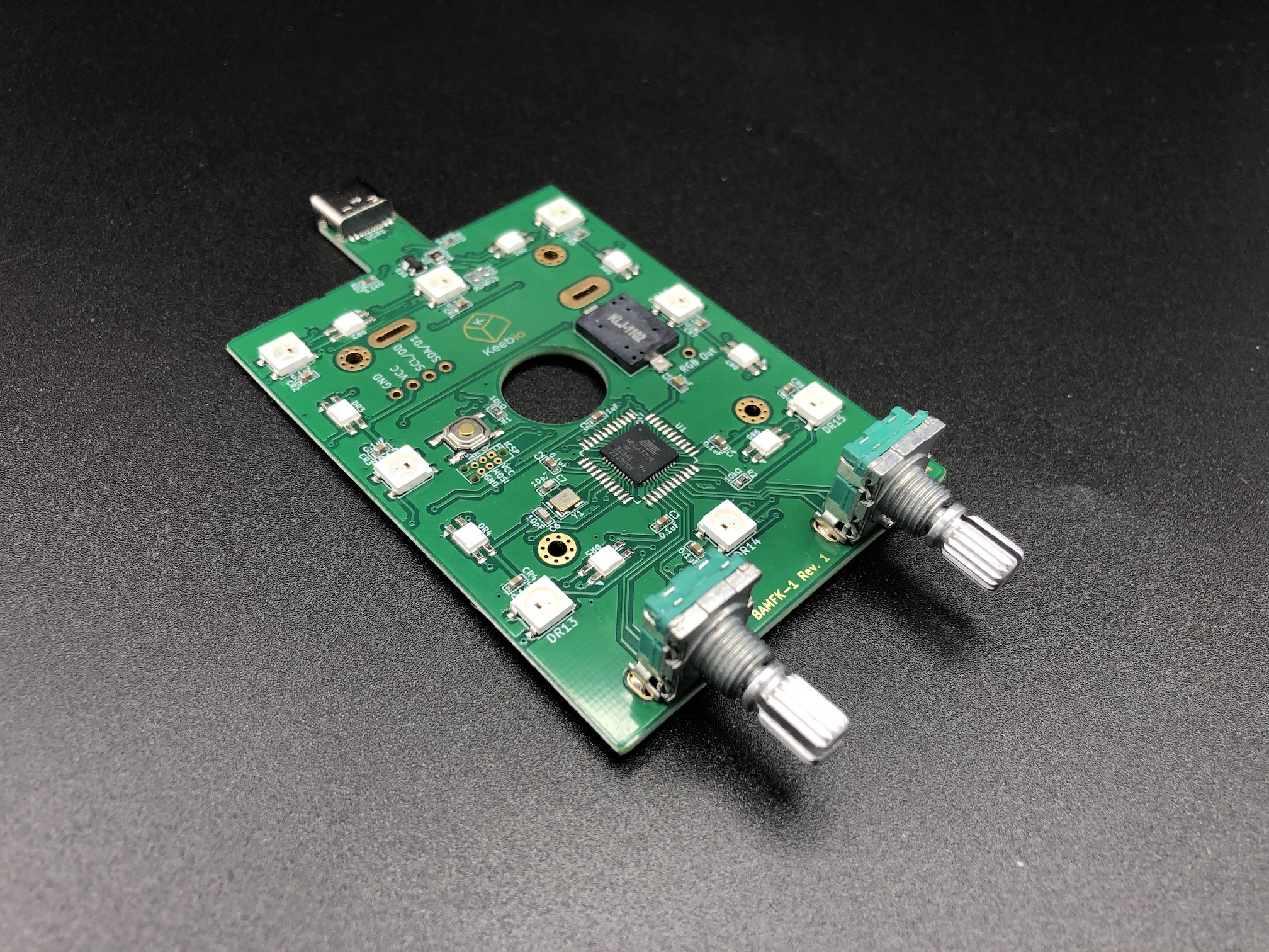
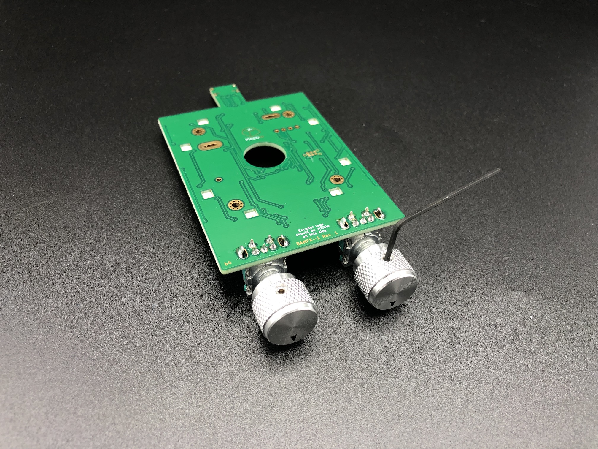
Install Knobs
Install the knobs onto the rotary encoders and use the 1.5mm hex key to tighten them into place. It'll be more difficult if you screw on the knobs later, so do it now.
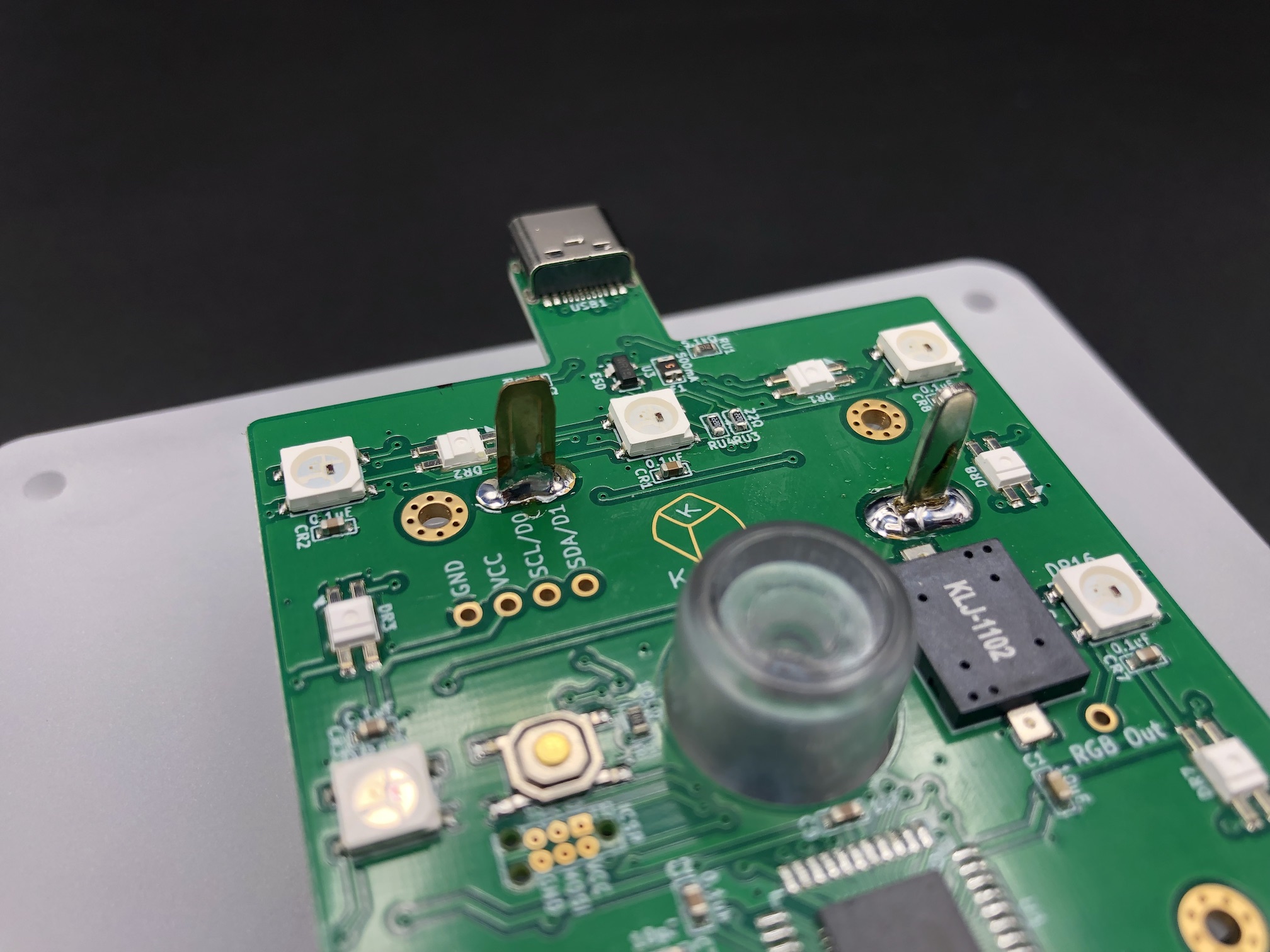
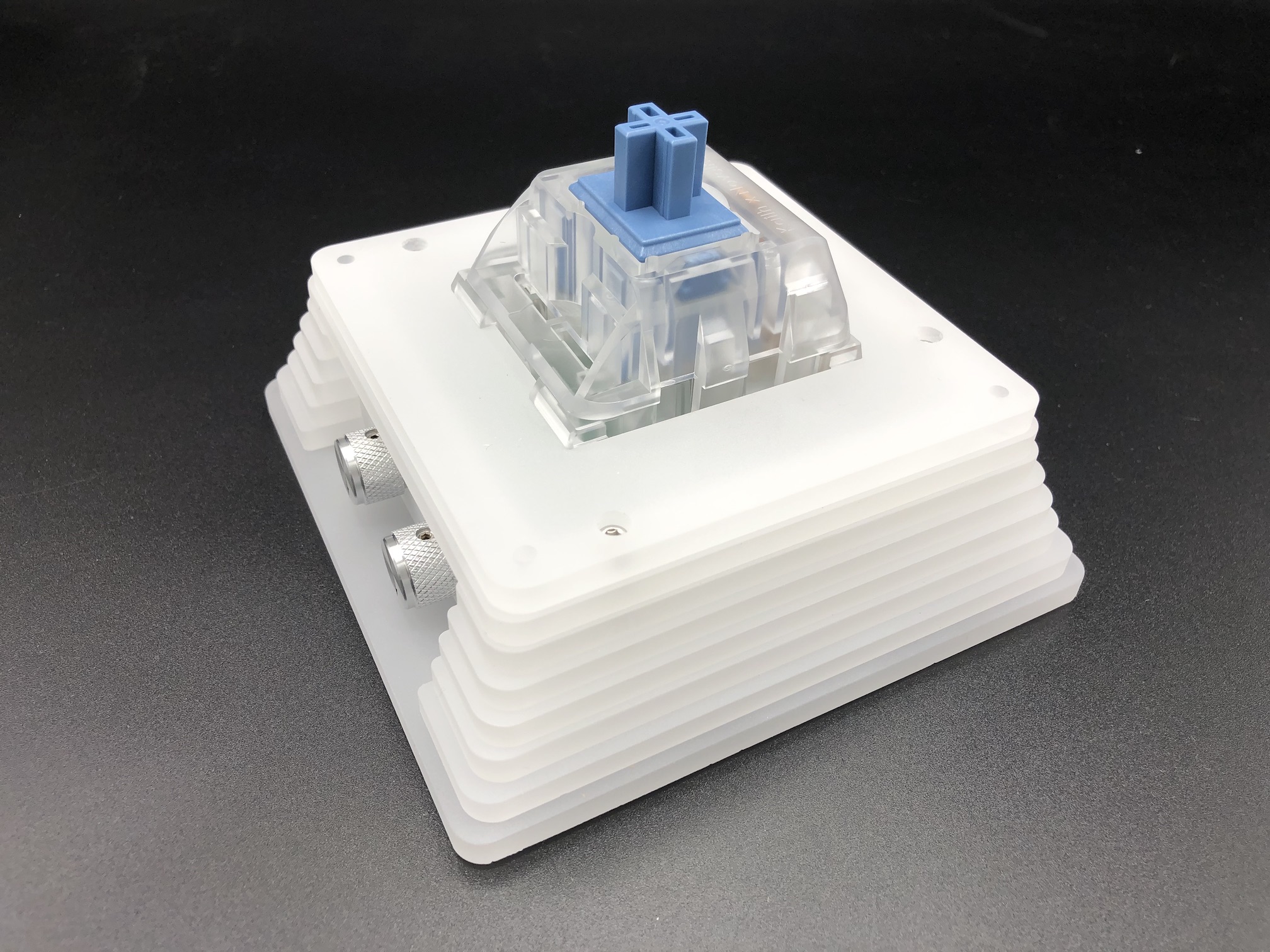
Solder Big Switch
Insert the switch legs of the Big Switch through the PCB and solder them on. Make sure the solder sticks to both the switch leg and the pad on the PCB. You might need to keep your soldering iron tip at the joint for a bit longer than you would with a normal-sized switch. Also add solder to both sides of the legs.
It's okay to use a generous amount of solder to get everything in place more firmly. If you don't use enough solder, the PCB might hang off of the switch at an angle.

Insert Plate into Case
Take the plate/PCB/switch combo and angle in the knobs through the front panel first, and then lean the USB port back.
Push the plate over the screw heads of the bottom half of the case.
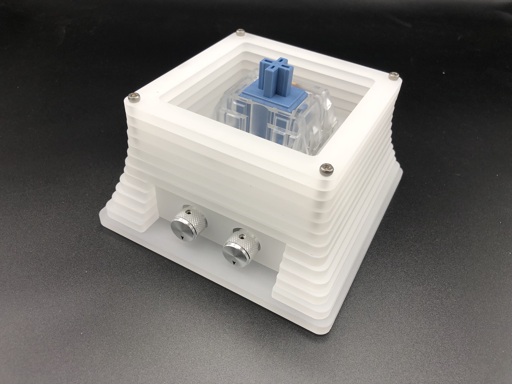
Reassemble Top Half of Case
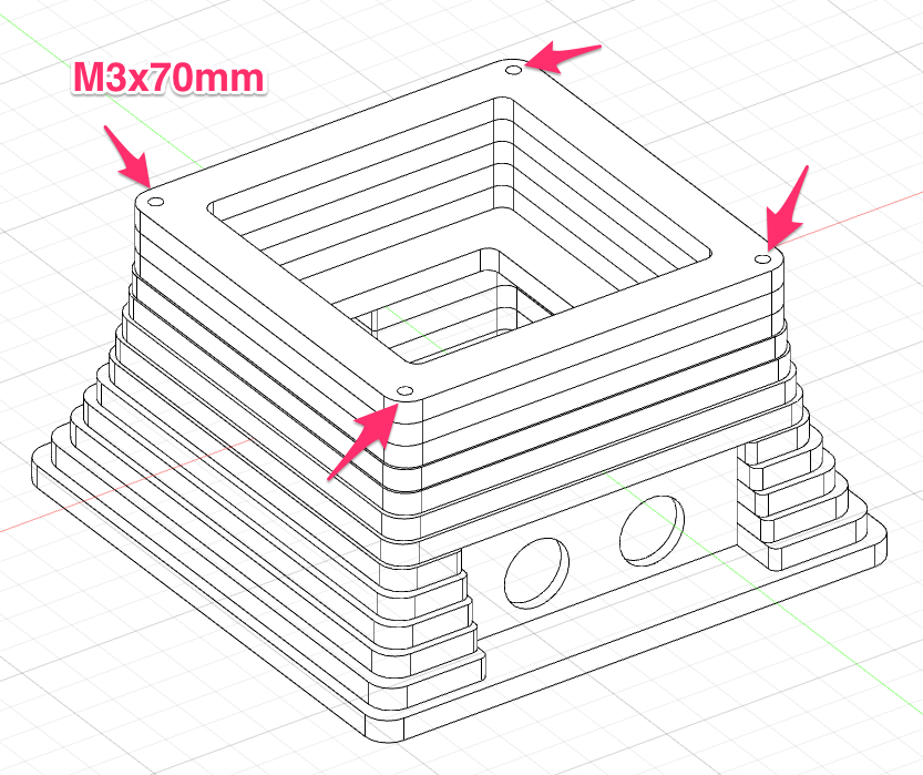
Add the rivet nuts to the underside of the bottom plate, stack all the top layers in place, and then screw them in.
If you need help with identifying the top 5 layers, see this: Making Top Half of Case.
It helps to do 2 opposite corners first, and then the last 2 corners.
Finishing It
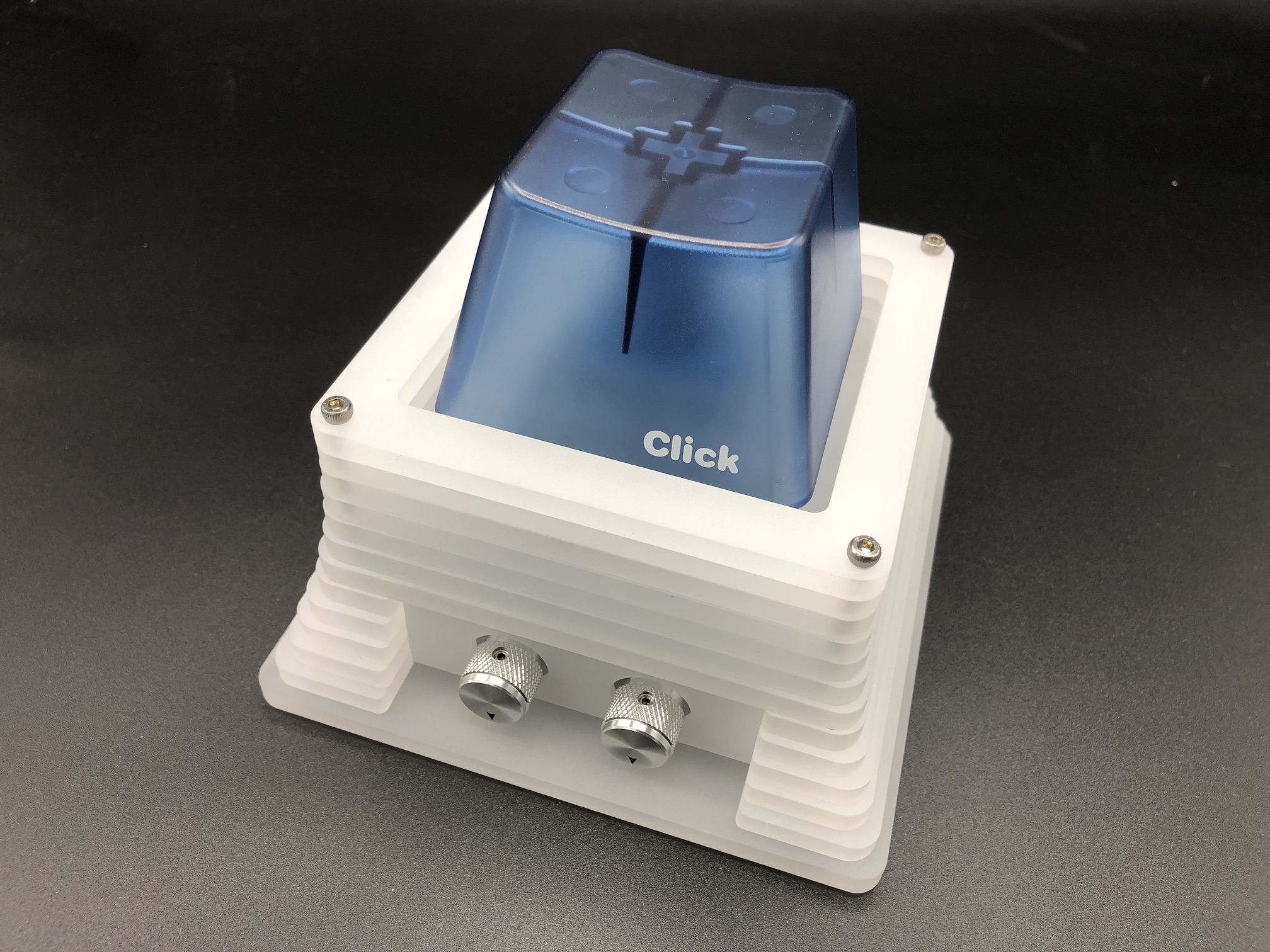
Add keycap.
Plug in USB-C Cable.
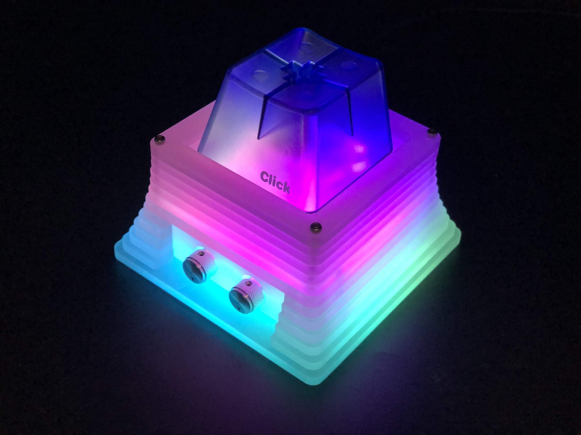
Turn the lights off and enjoy.
Reprogramming the BAMFK-1
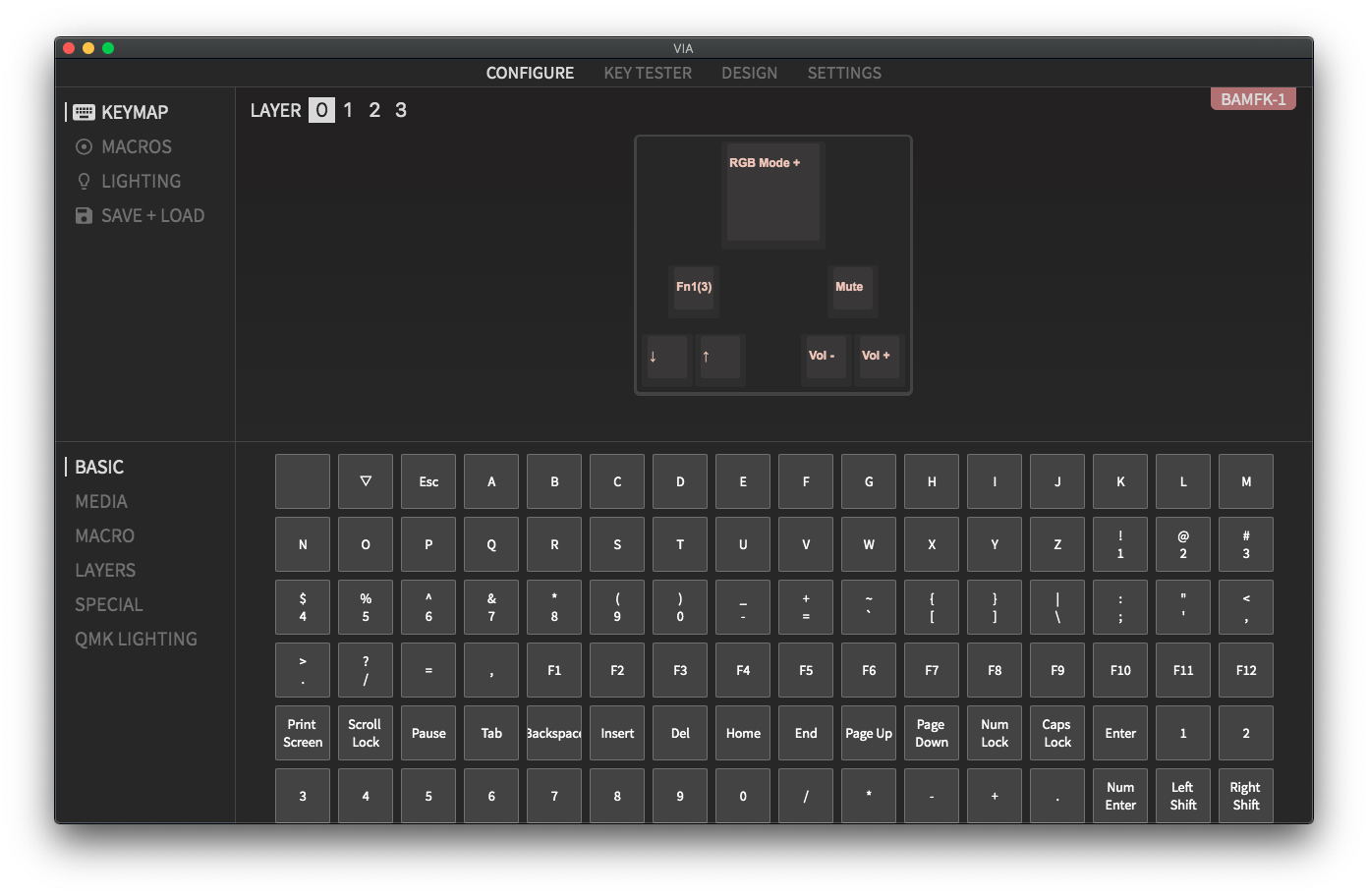
You can reprogram the BAMFK-1 using QMK, QMK Configurator, or VIA Configurator. The encoder rotations and presses can be programmed as well.
QMK Configurator
Here's the link for configuring the BAMFK-1 with QMK Configurator: config.qmk.fm
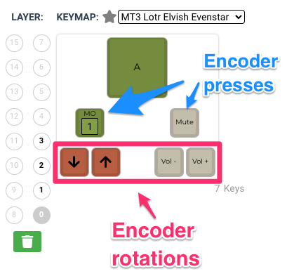
VIA Configurator
Full Reassembly of Case
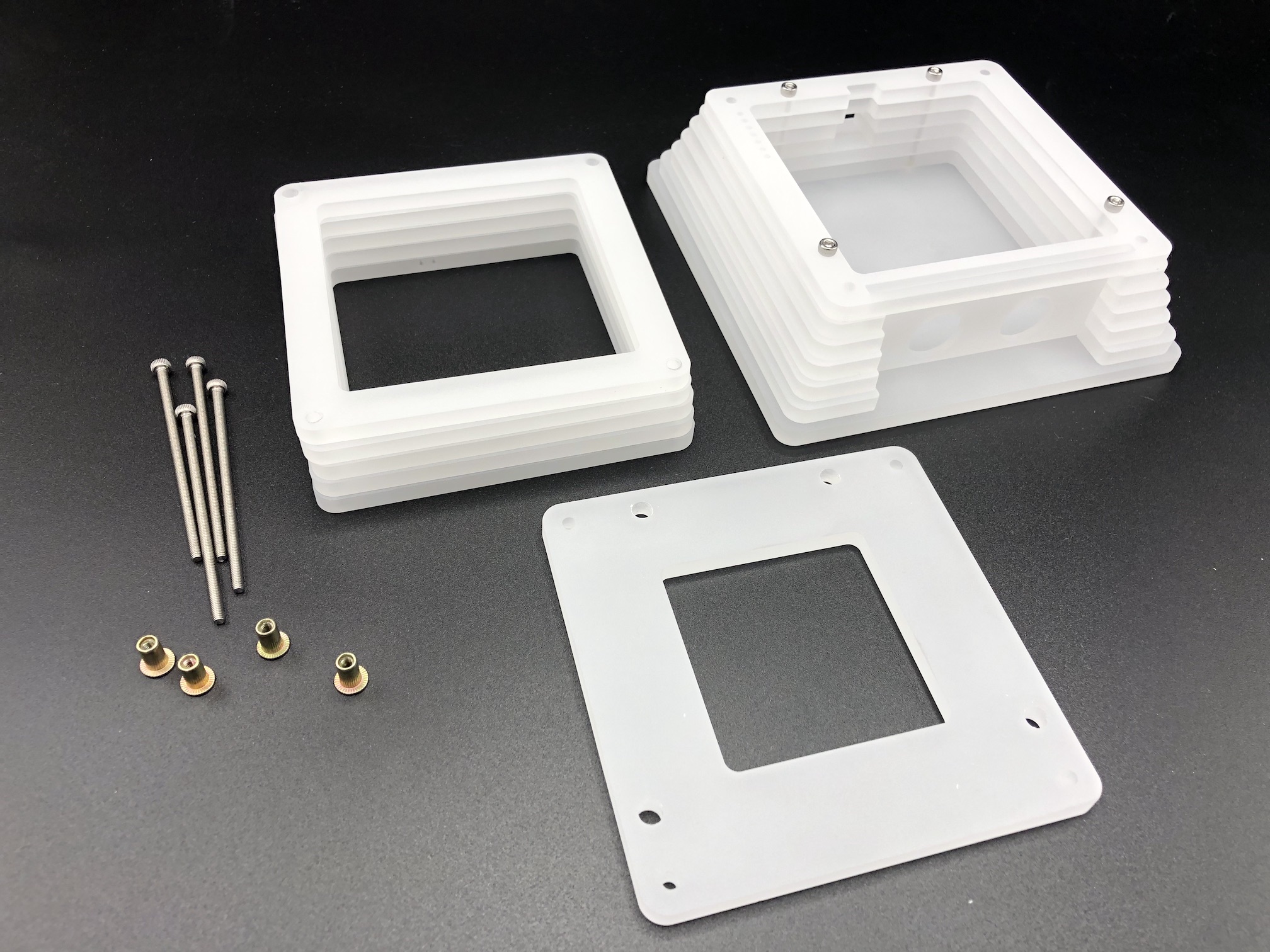
If you've completely disassembled the case, here's how to put all the pieces back together.
First you'll need to identify all of the pieces. Each piece has a number of registration dots to assist with identification and placement, since some of the layers are similar in size.
The registration dots are aligned towards the left side of the case, except for the layers that come in two pieces (and thus will have dots on both the left and right sides).
Make Bottom Half of Case
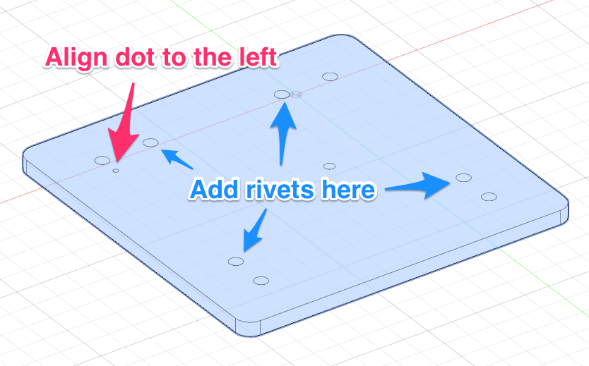
We are going to assemble the case, starting from the bottom plate.
Make sure the registration dot is aligned to the left. Then add rivet nuts on the underside of the plate in the spots indicated below.
Find the piece with 2 dots and stack it on top of the bottom plate.
Do the same with the piece with 3 dots.
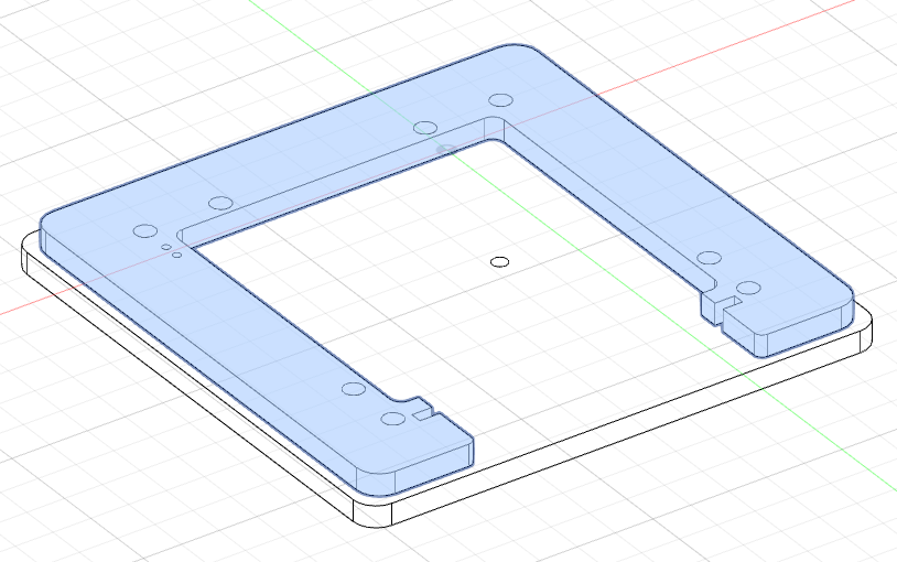
There will be two pieces with 4 dots.
Then put on the two pieces with 5 dots.
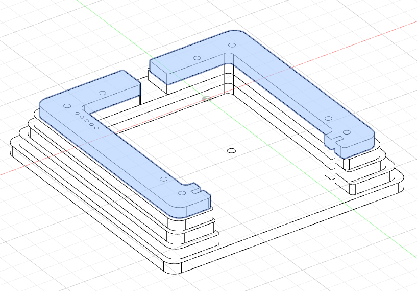
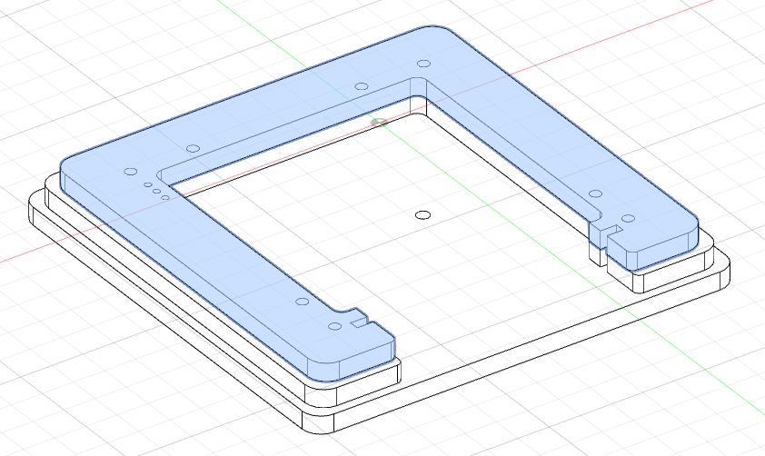
Add the piece with 6 dots.
Add the piece with 7 dots.
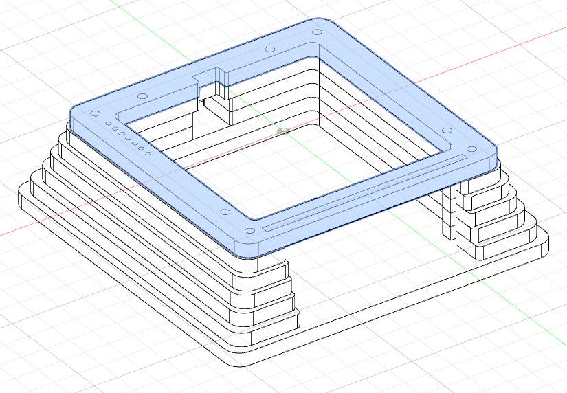
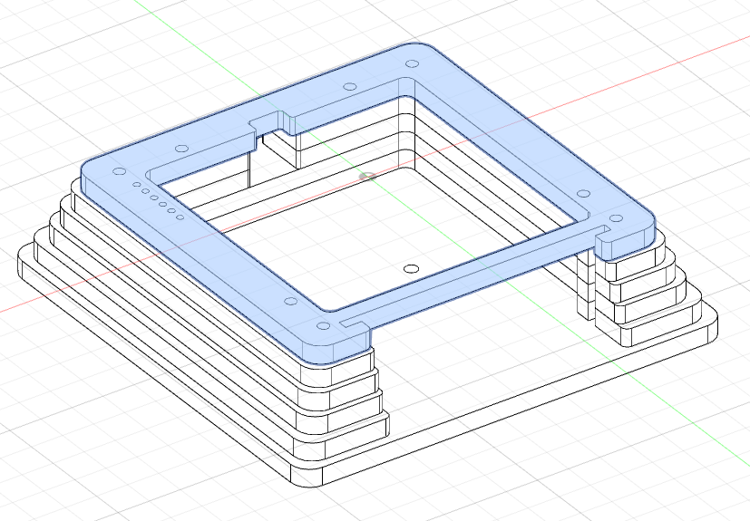
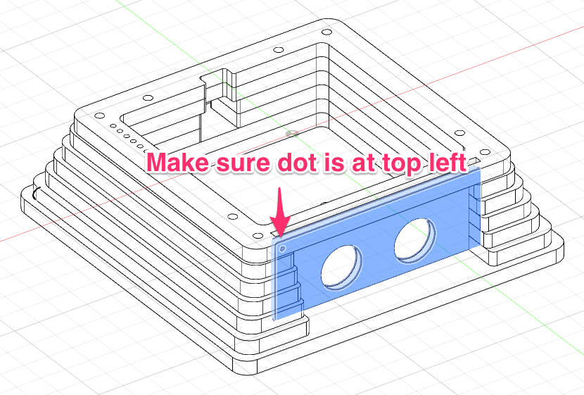
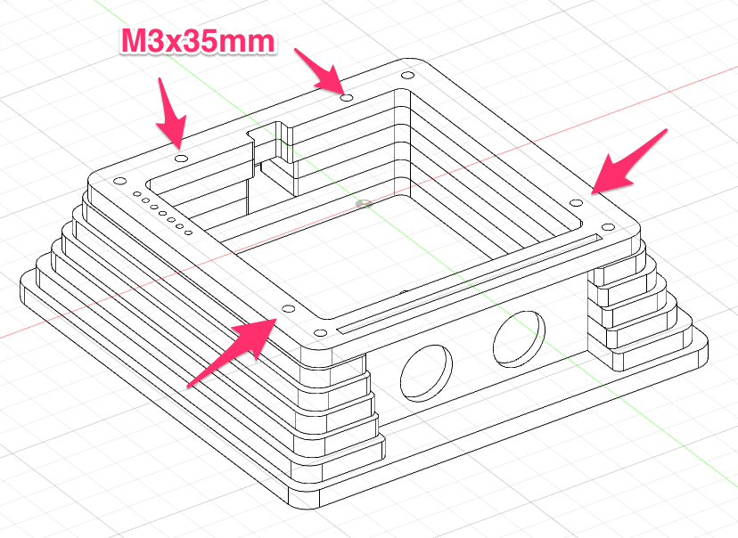
Insert the front panel piece, making sure the registration dot is aligned to the top left.
Take the 35mm M3 screws and slot them through all the pieces stacked so far and screw them into the rivet nuts.
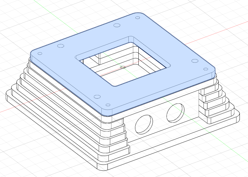
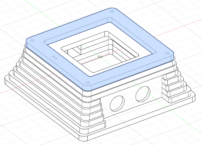
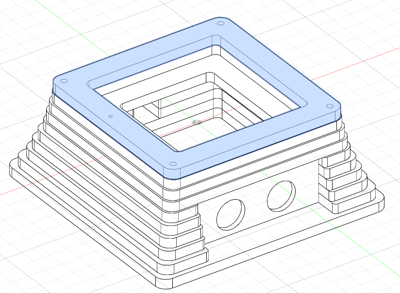
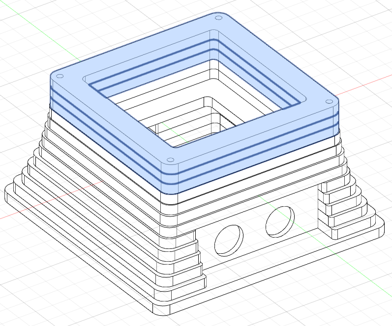
Make Top Half of Case
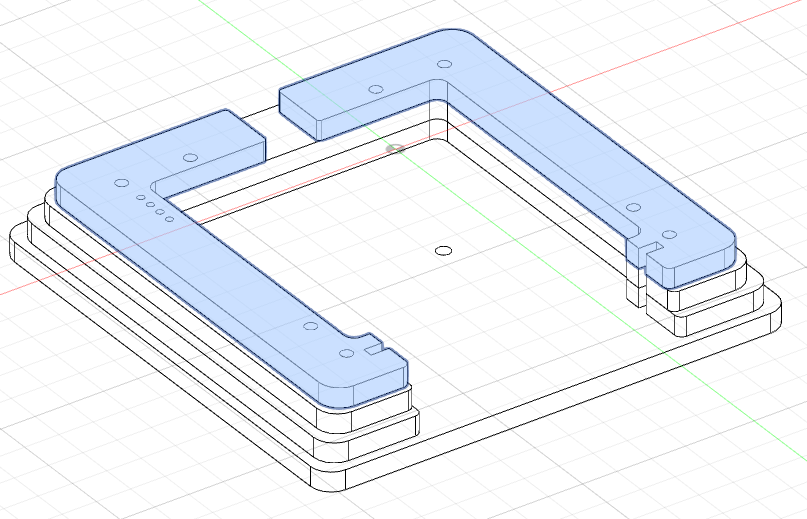
Add the switch plate.
Add the piece with 2 dots.
Add the piece with 1 dot.
The last three pieces are all the same size and have no dots.
Add the remaining rivet nuts to the bottom plate and screw in the 70mm M3 screws into them.