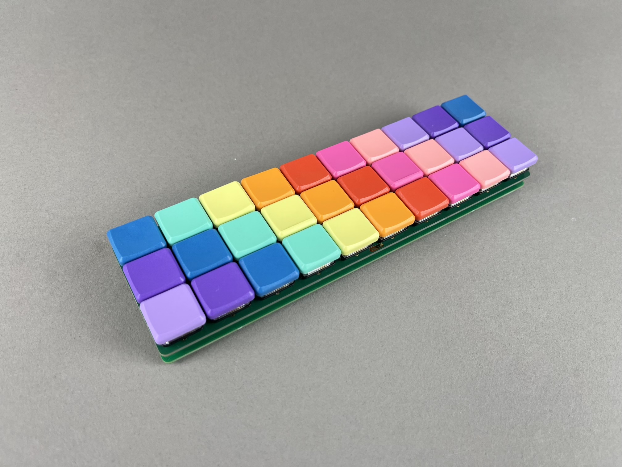
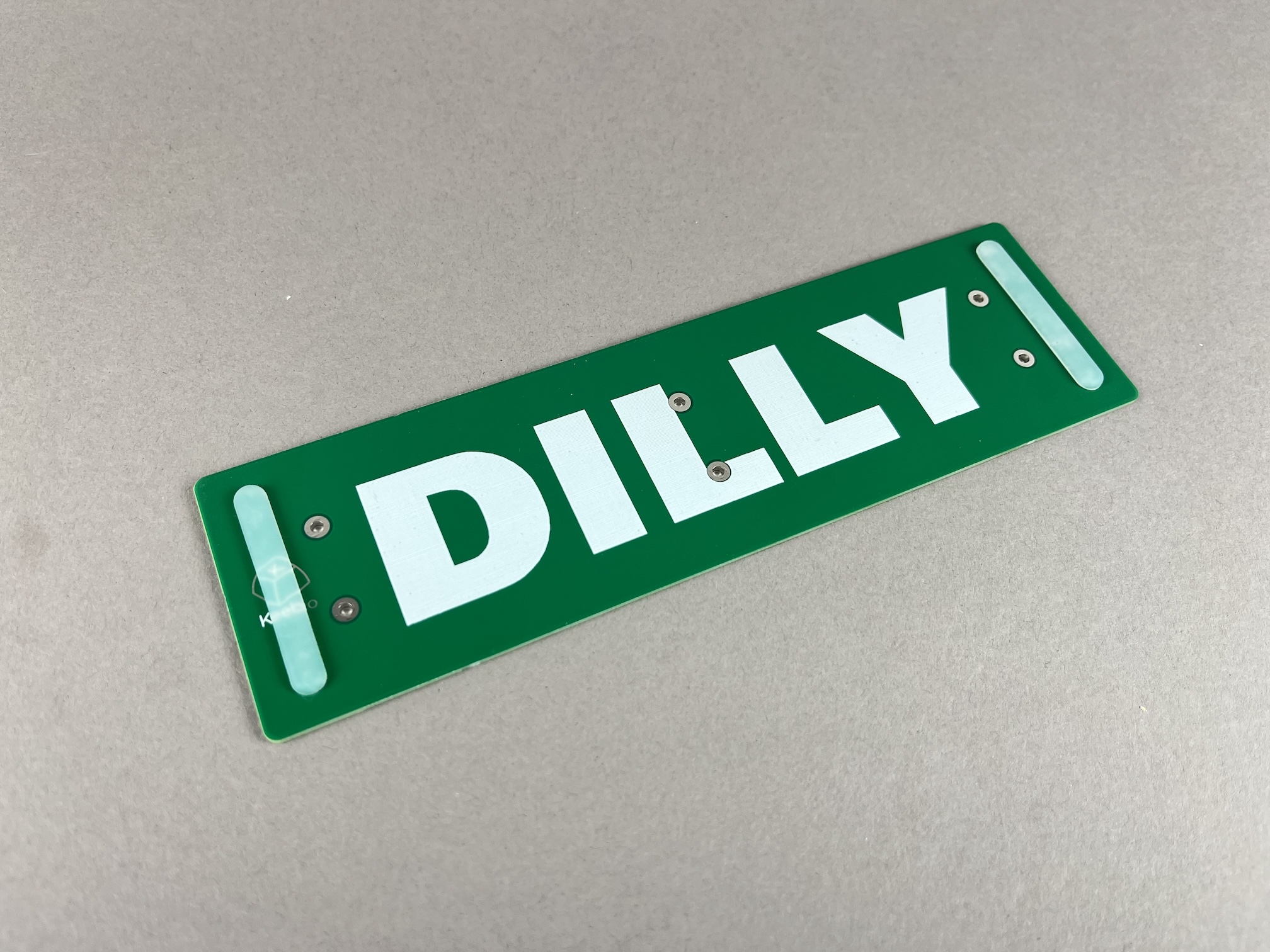
Dilly
Parts List
Here's a list of parts needed for the build:
- 1 Dilly PCB & Bottom PCB Plate with M2 screws, standoffs, and SKUF feet
- 30 single-color LEDs (optional, for LED backlight)
- WS2812B RGB LED strip (optional, for underglow)
- 1 Pro Micro Compatible Microcontroller
- 30 Kailh Choc V1 Low Profile Switches
- 30 Kailh Choc V1 Low Profile Keycaps
- Electrical tape or Kapton tape
Build Steps
Here's a summary of the build steps:
- Prepare components
- Solder Pro Micro header pins
- Solder switches
- Solder LEDs (optional)
- Flash Pro Micro
- Solder Pro Micro
- Solder RGB strip (optional)
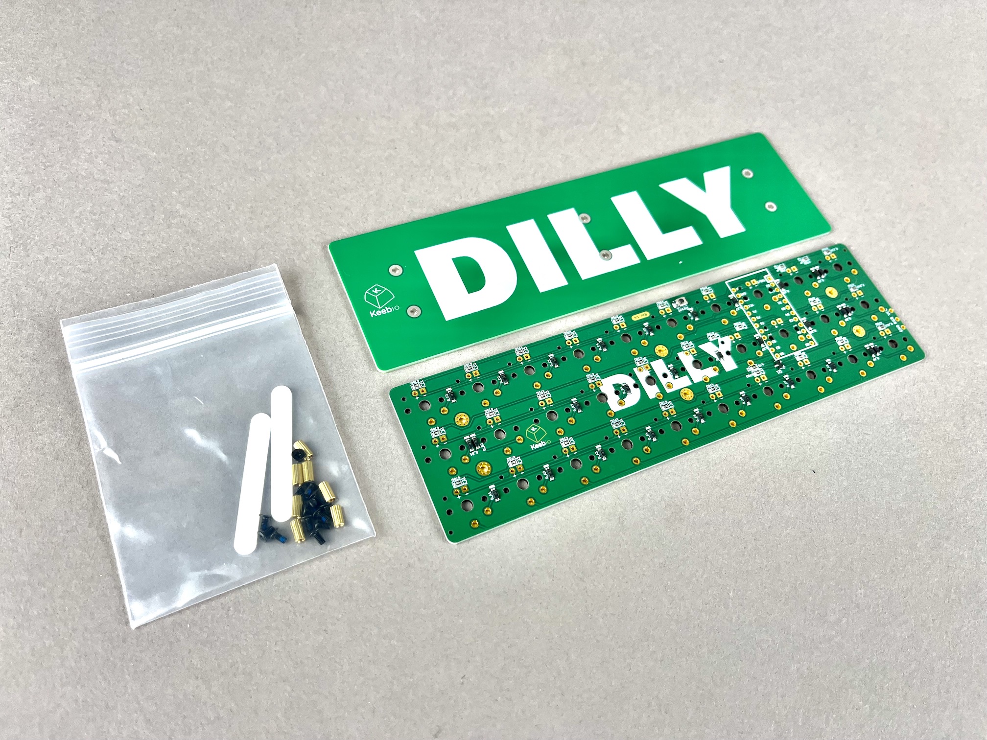
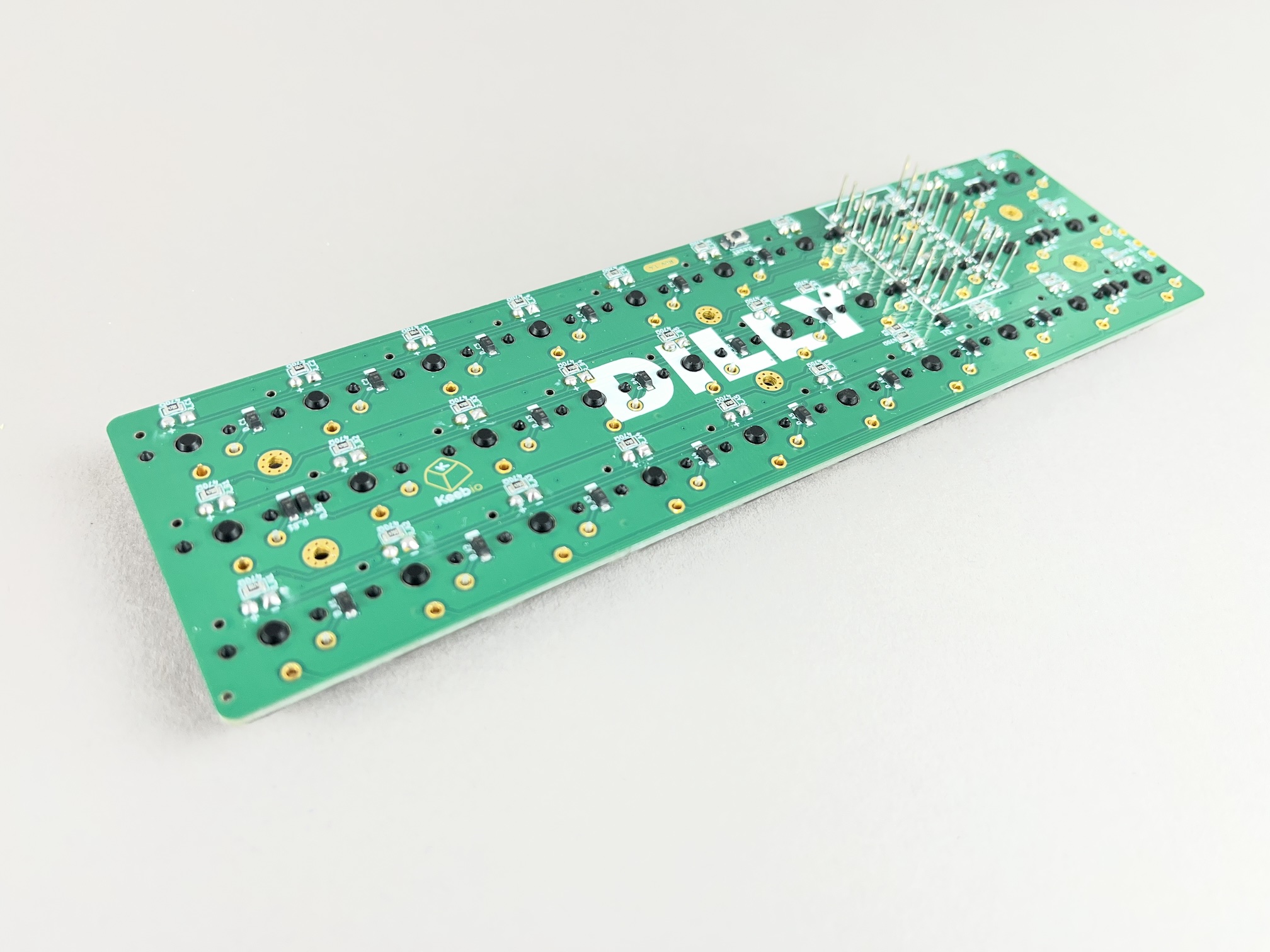
Inspect Parts
Check that you have a PCB, bottom plate, M2 screws, and standoffs.
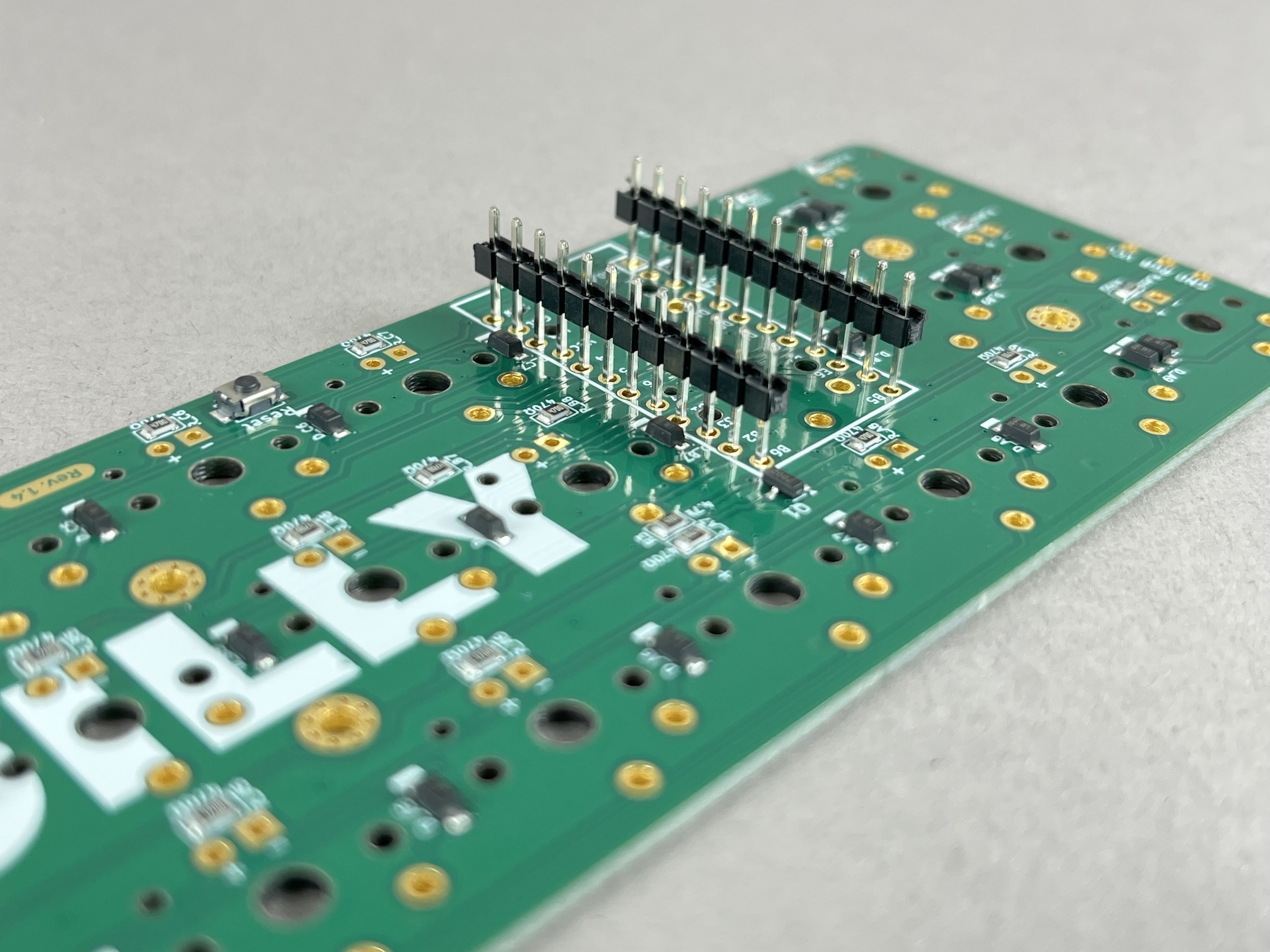
Solder Pro Micro header pins
For the microcontroller, you'll want it to be as close as possible to the underside of the PCB. So put the header pins upside down on the PCB and solder them in.
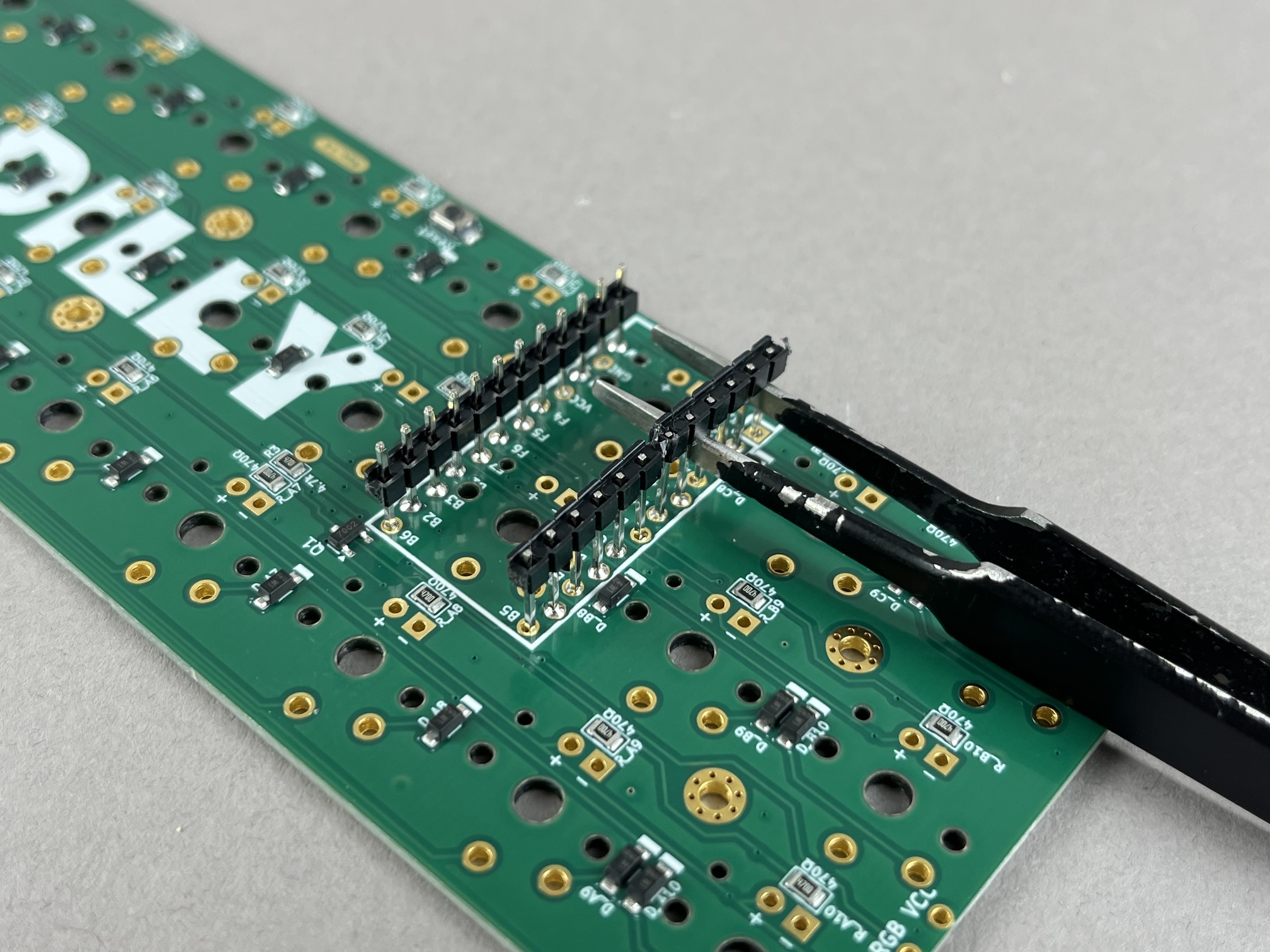
Next, pry up the plastic pieces on the header pins.
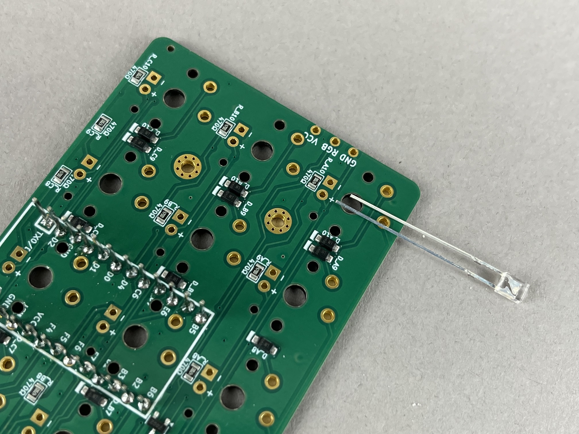
Solder LEDs (Optional)
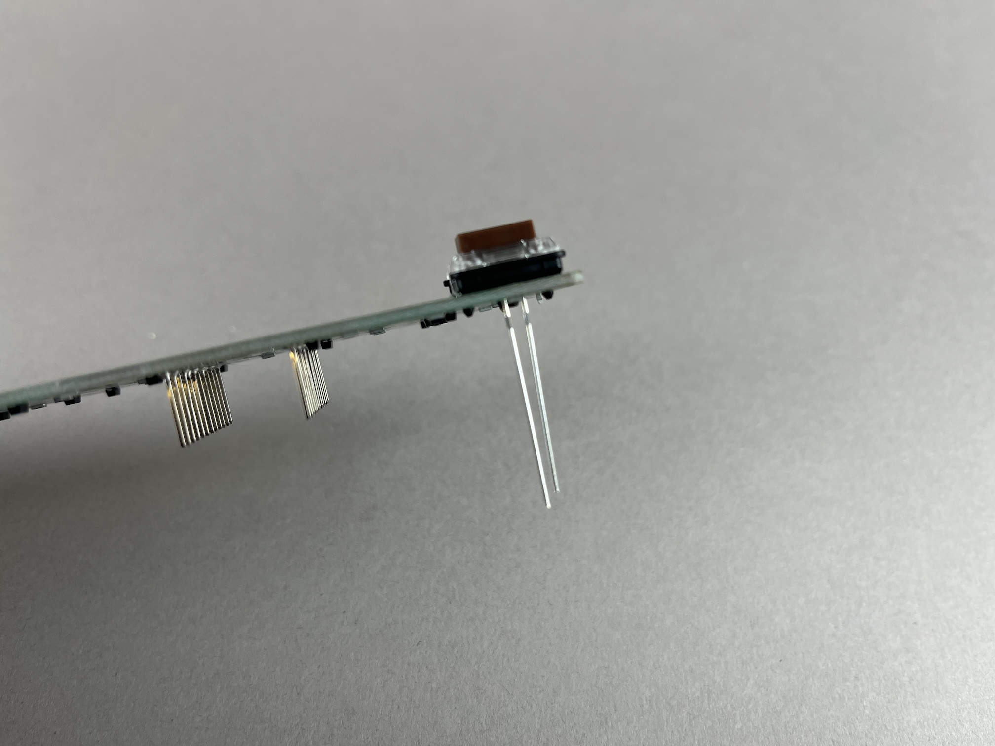
Line up the longer leg of the LED to the + pad on the PCB, and the shorter leg of the LEd to the - pad, and then insert it through the PCB.
Place a switch over the LED to help hold it in place.
Flip the PCB over and solder the LED in place.
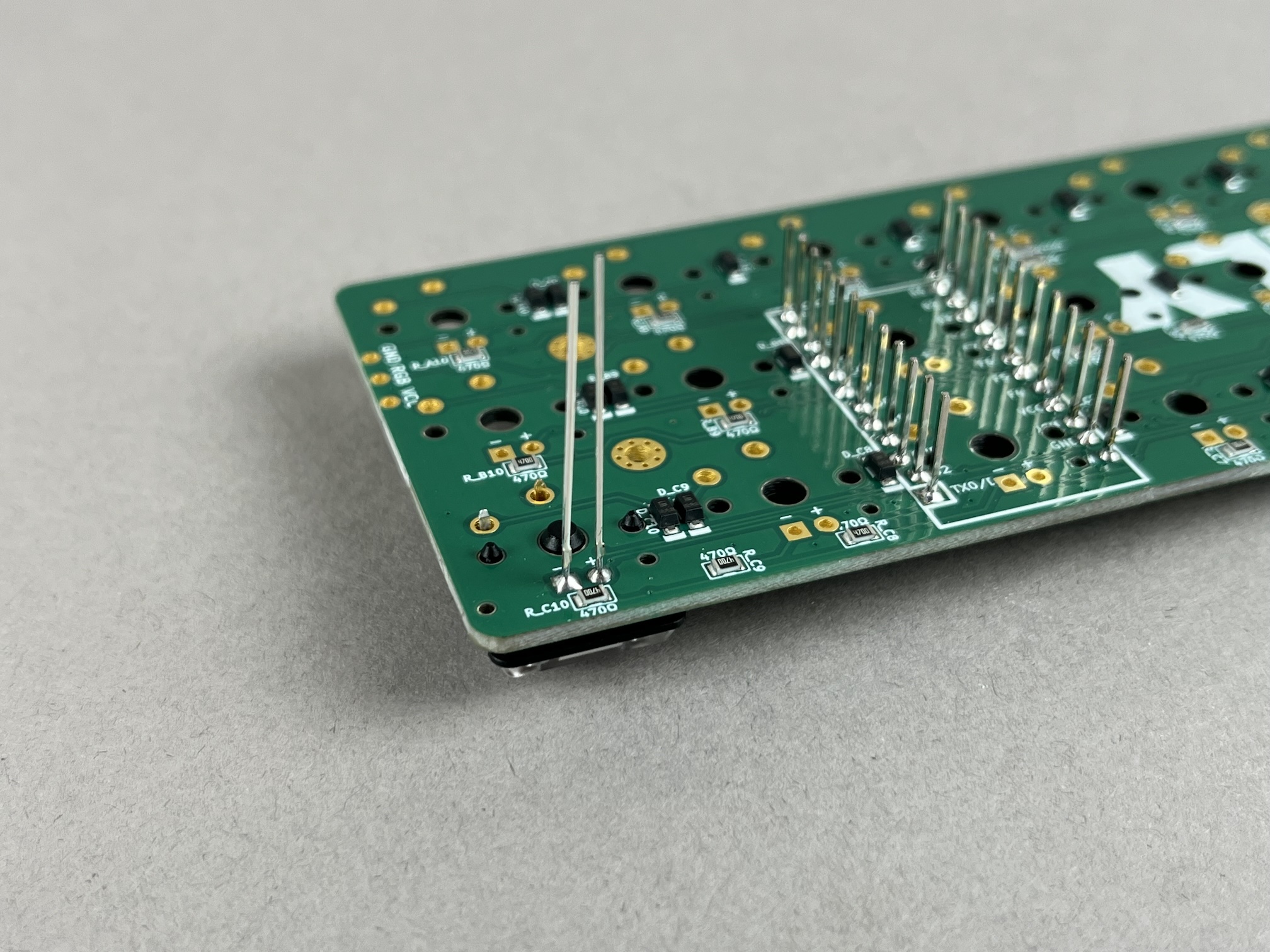
Then clip the excess length of the legs of the LED.
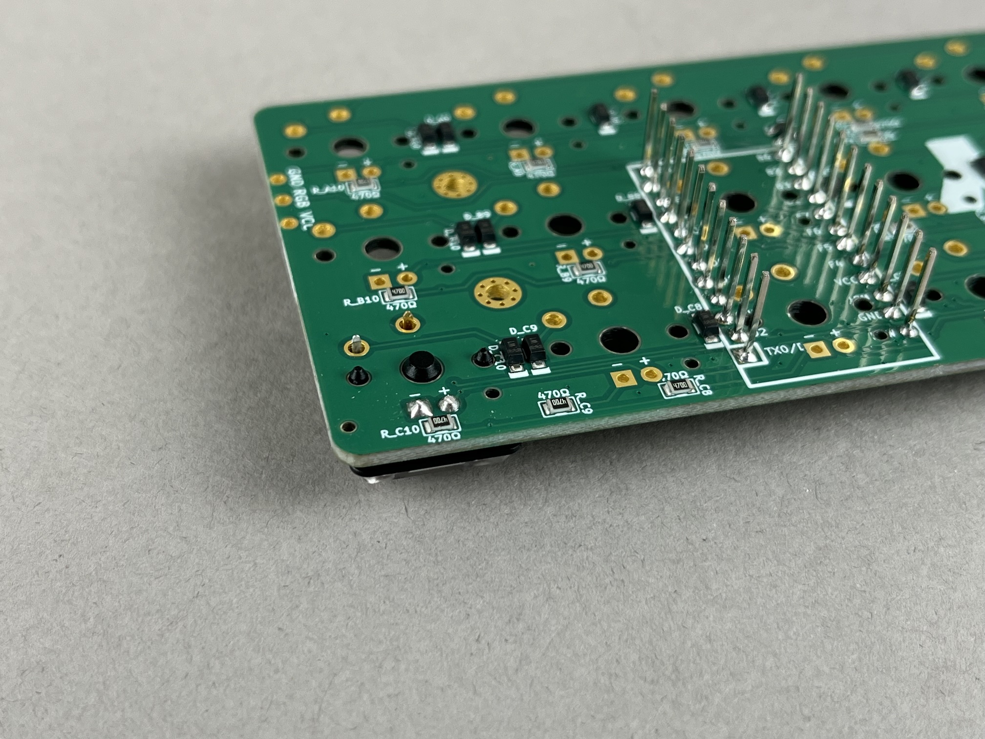
Repeat for all the LEDs.
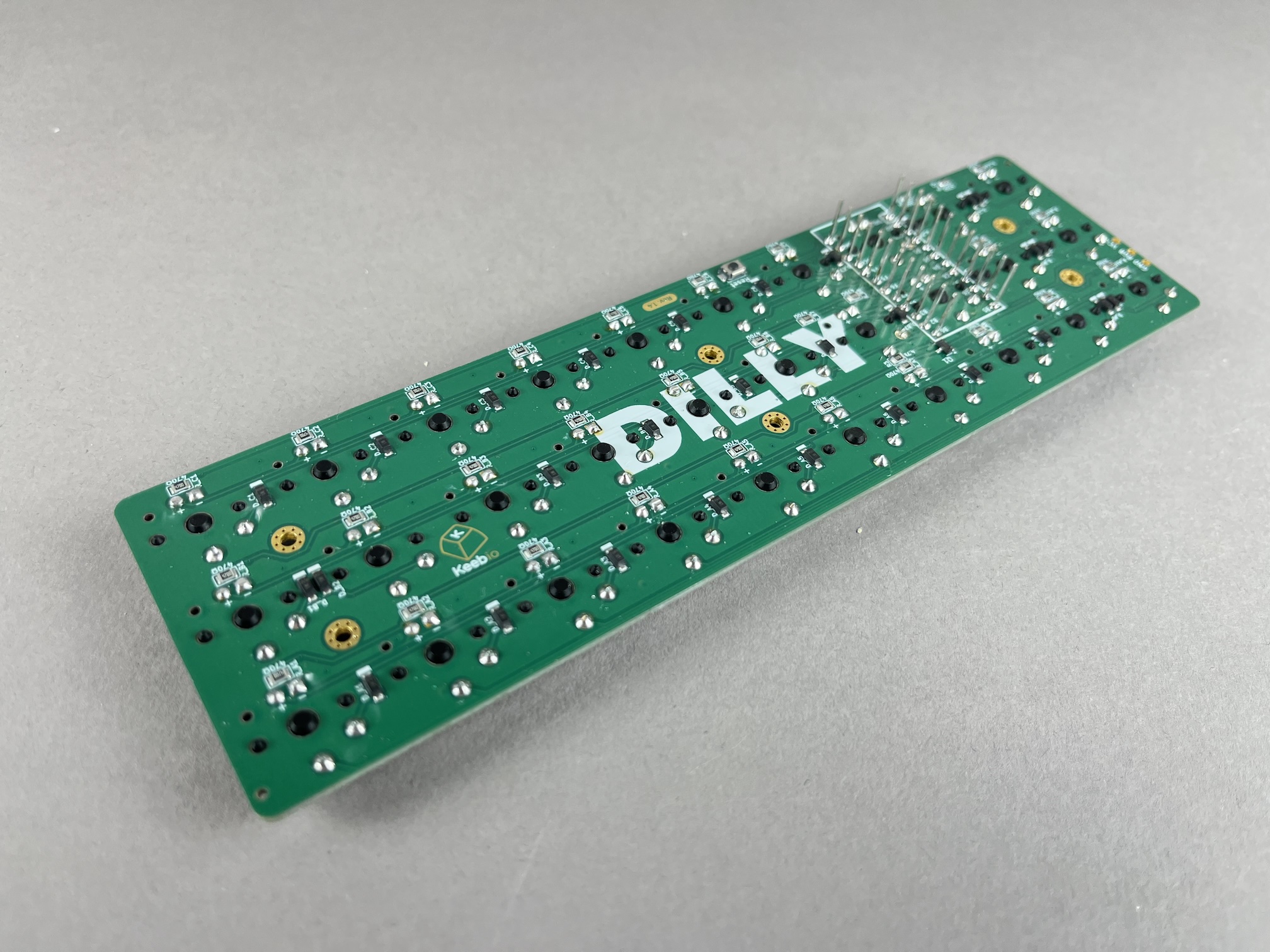
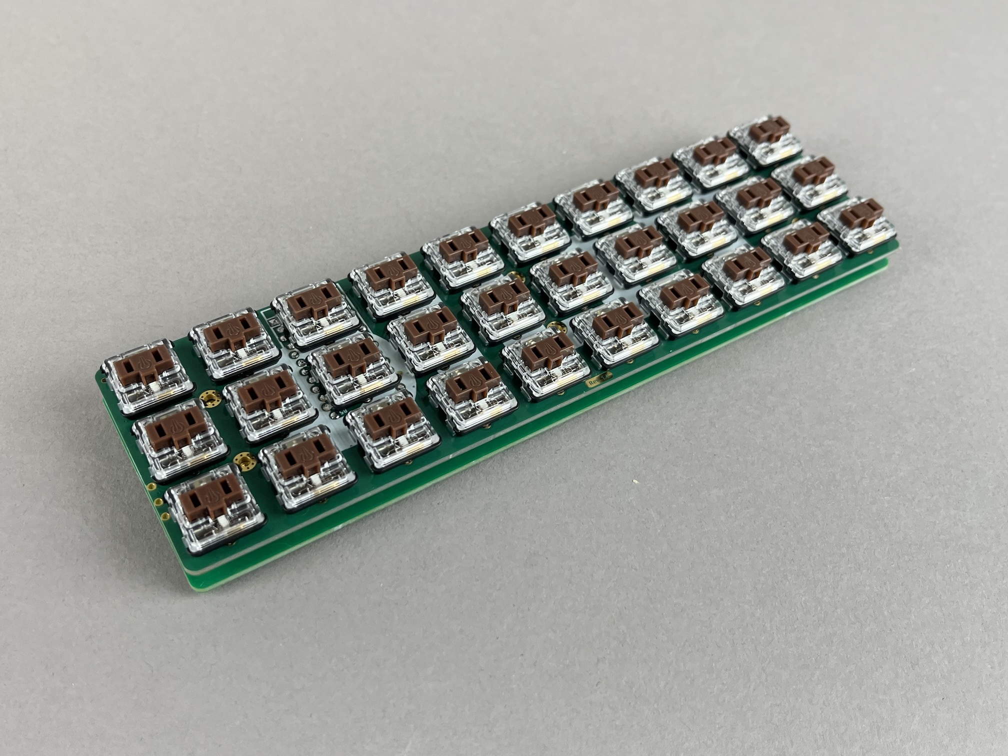
Solder Switches
Place switches on to the PCB if not already done so.
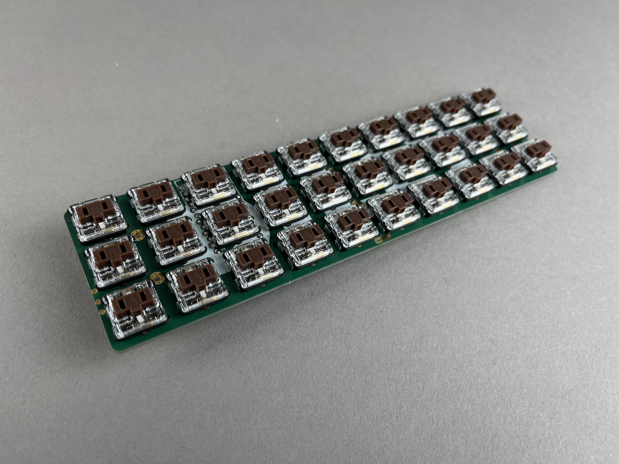
Flip the board over and solder them all in.
Prepare and solder the microcontroller
Before soldering the microcontroller, flash the firmware to it and make sure it gets detected as a keyboard by your computer.
You can find pre-compiled firmware QMK builds with VIA enabled for the Dilly here for some microcontrollers:
If using the RP2040 Pro Micro, you'll need to short the BOOT and GND pins and then press the reset button on the PCB to get the microcontroller into bootloader mode.
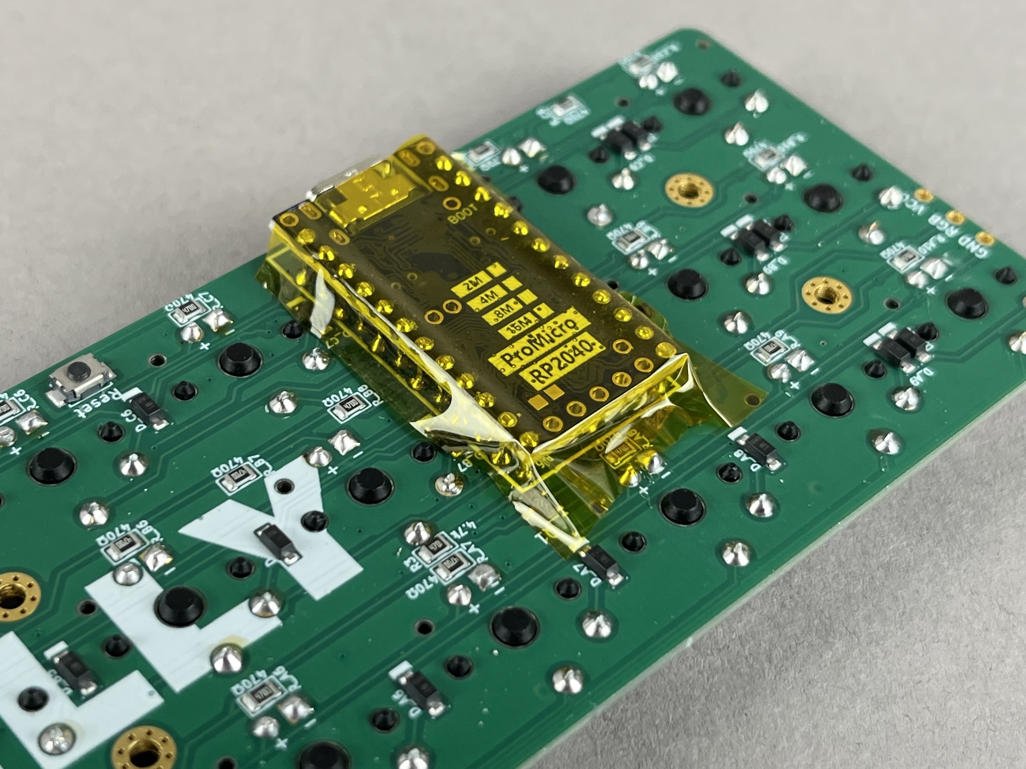
Put some electrical or Kapton tape on top of the area the Pro Micro will be:
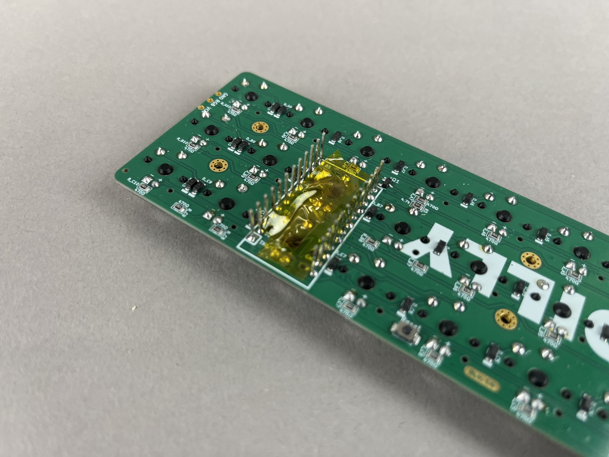
Insert Pro Micro over the header pins, making sure the correct pins are being used. For instance, with the RP2024 Pro Micro, ignore the top two pins.
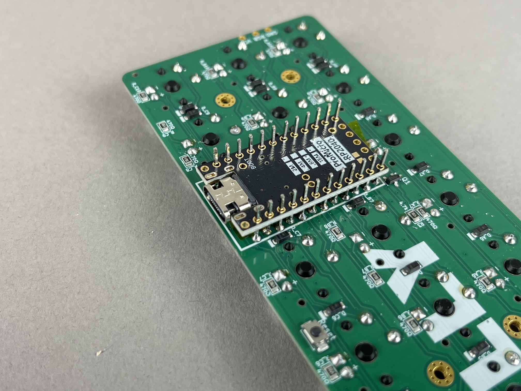
Solder the two pins closest to the USB port and make sure the microcontroller is level.
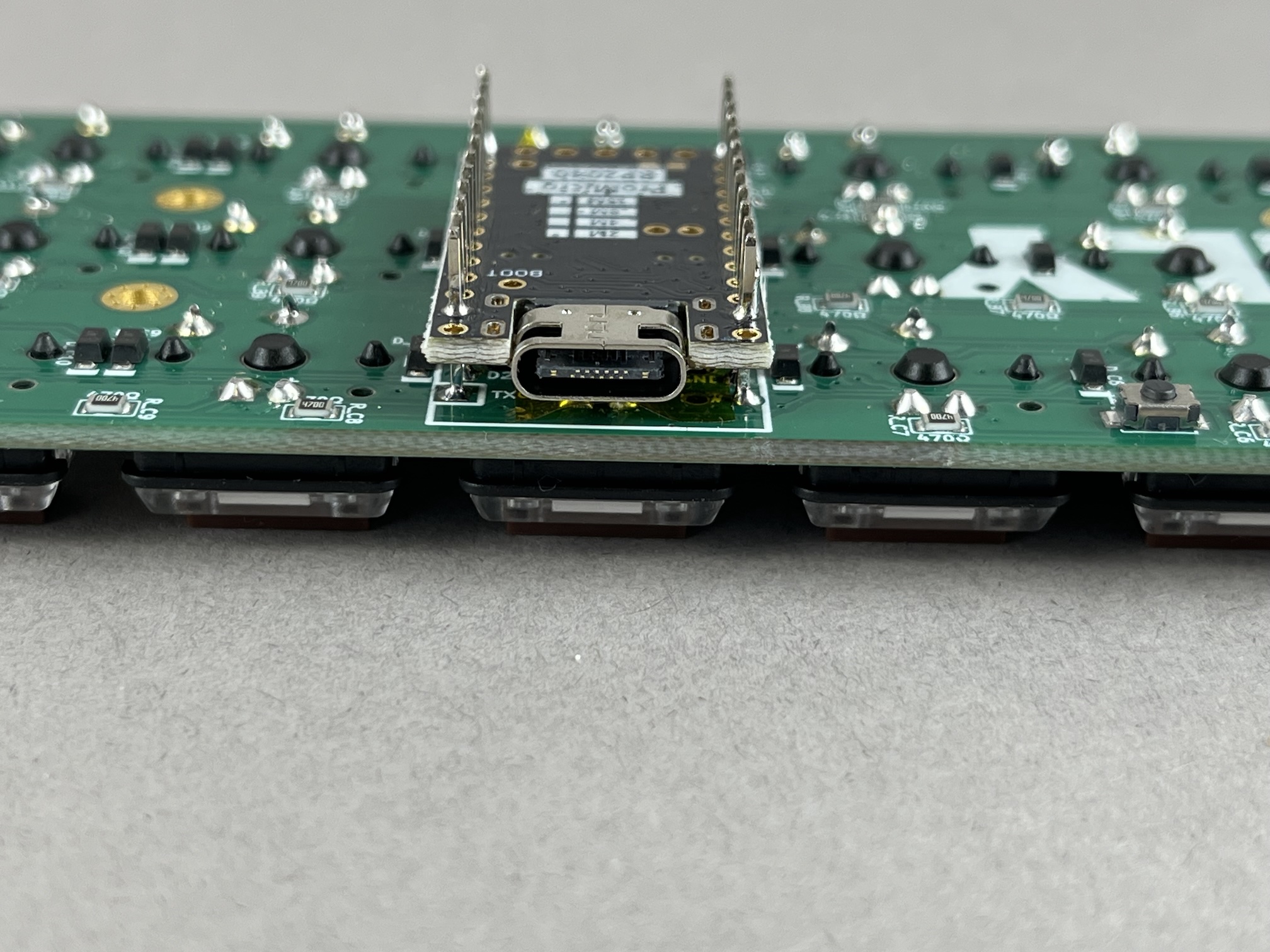
Next solder the two other corners in and make sure everything is aligned.
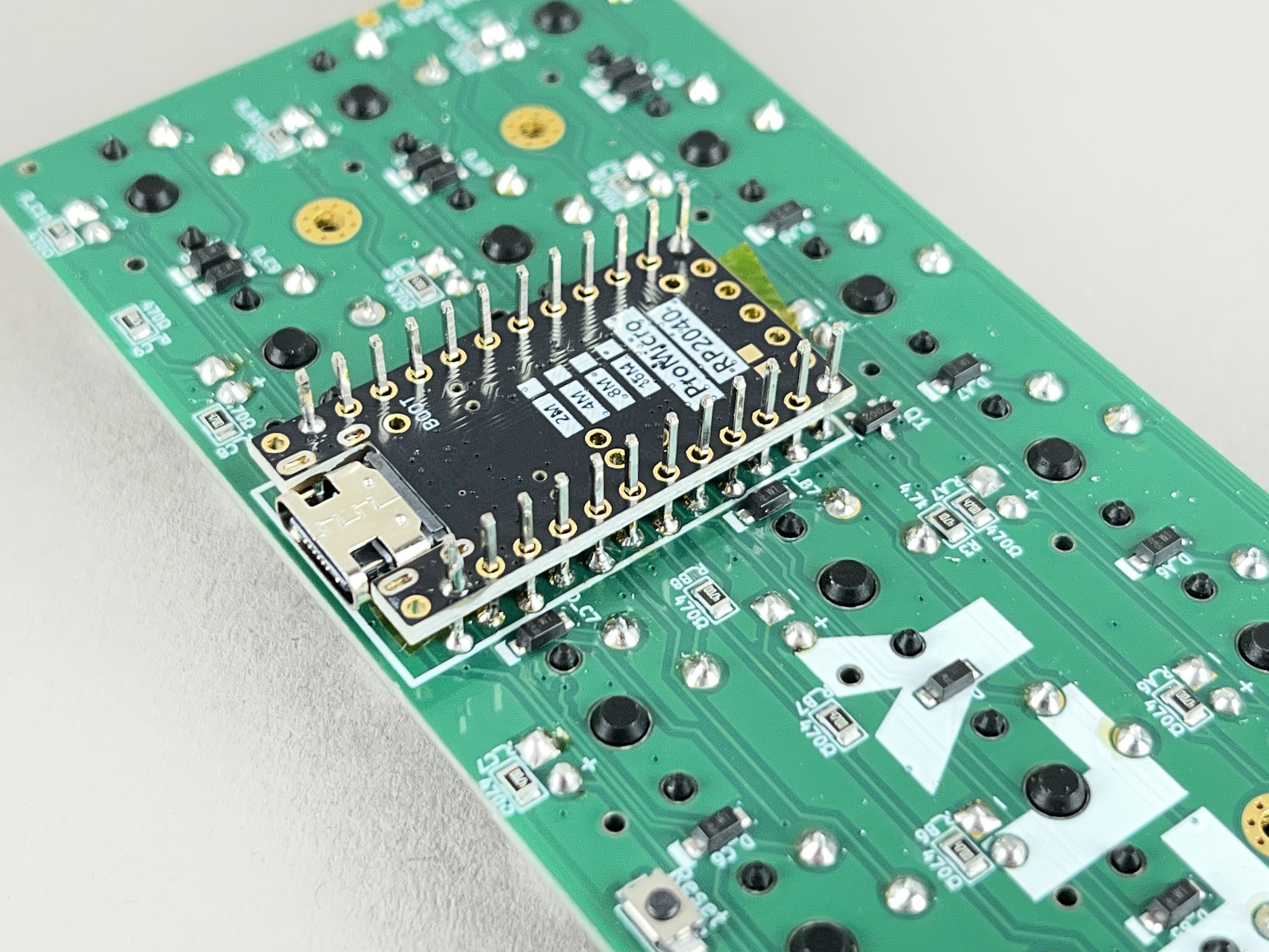
Solder the remaining pins and clip the excess length of the legs of the header pins.
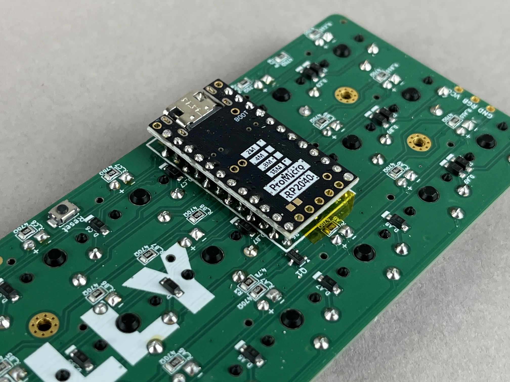
Add tape over the microcontroller to prevent any short circuits from it touching the bottom plate.
Add RGB Strip (Optional)
Use the VCC/RGB/GND breakout pads on the PCB to connect the RGB strip to the microcontroller.
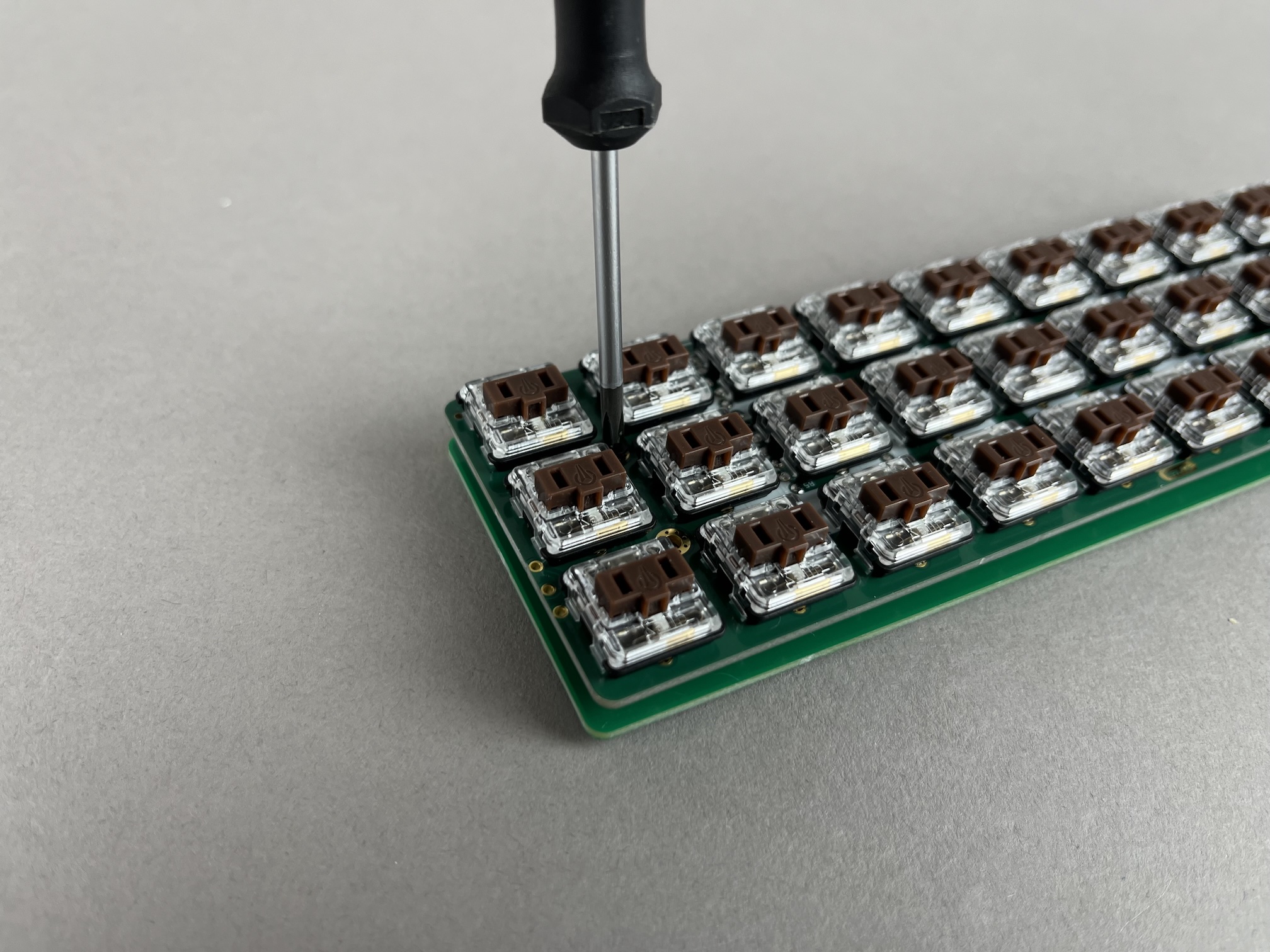
Assemble Case
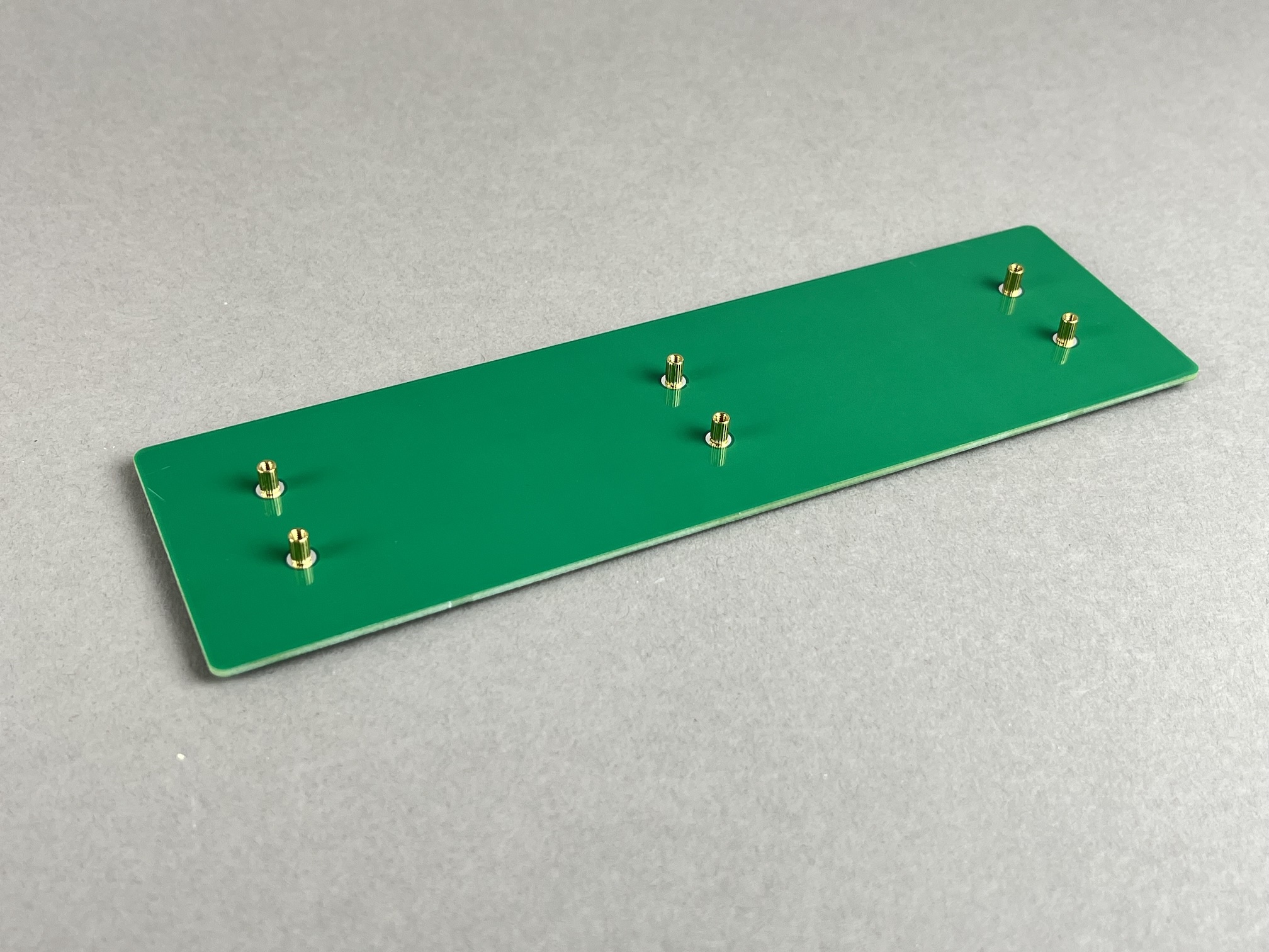
Add SKUF feet to the bottom plate.
Add a screw and standoff to the bottom plate.
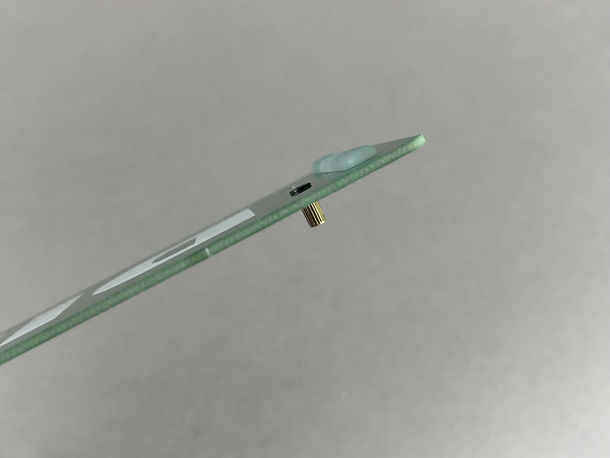
Repeat for the rest of the screws and standoffs.
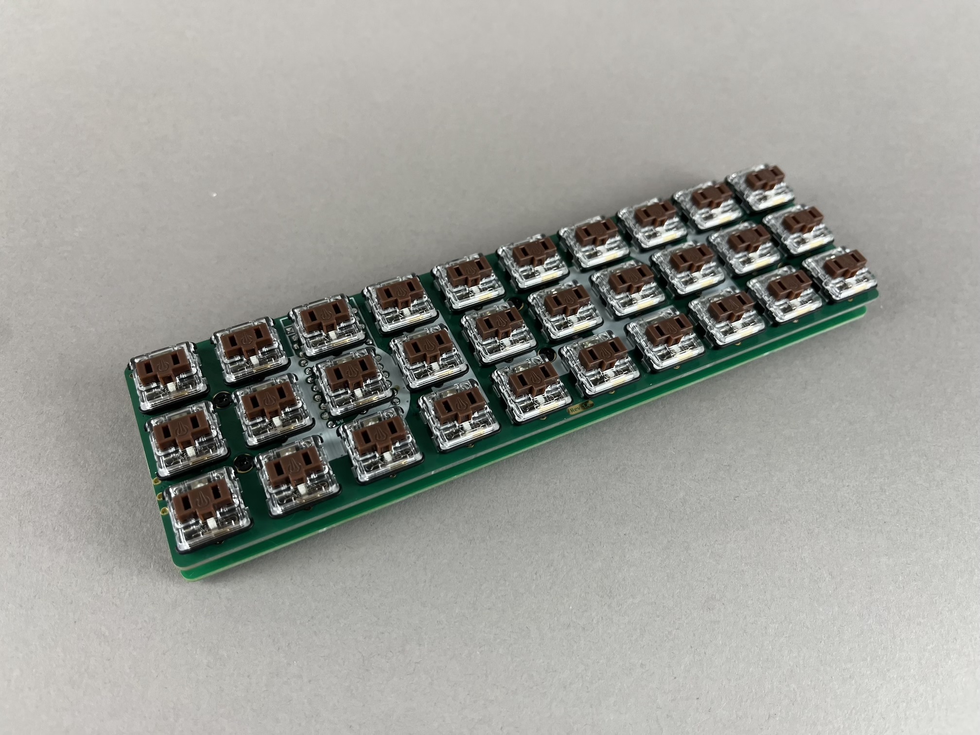
Place the PCB on top of the standoffs of the bottom plate.
Add screws through the PCB and into the standoffs of the bottom plate.
Repeat for the rest of the screws and standoffs.
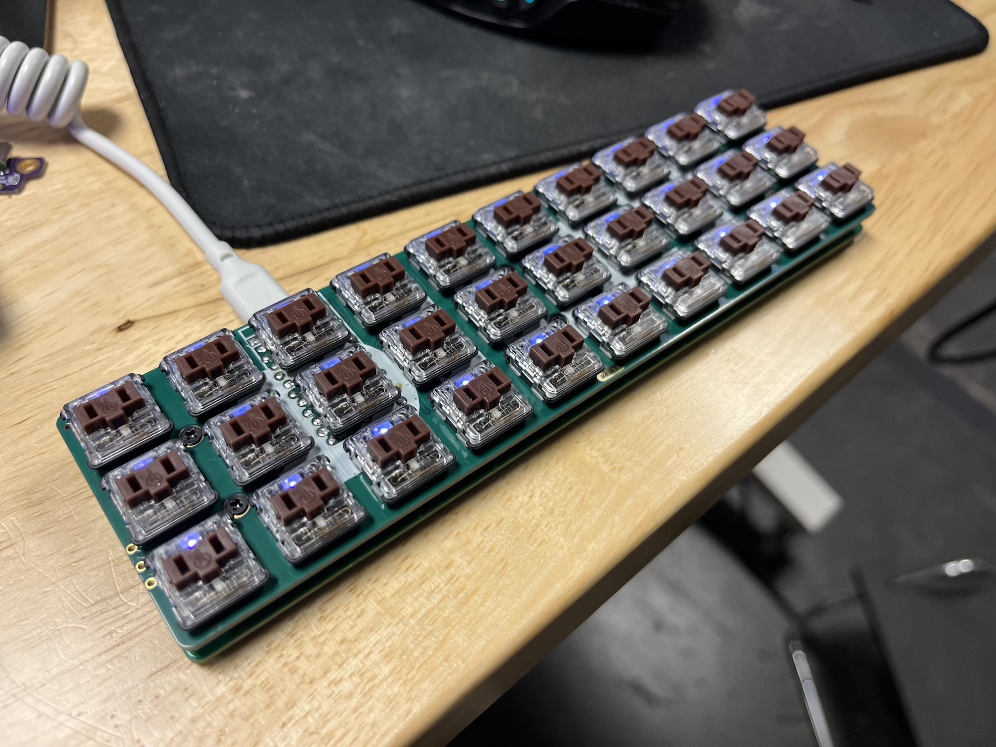
Plug in the USB cable
Plug in the USB cable into the PCB and make sure it gets detected as a keyboard by your computer
Add Keycaps
Add keycaps to all of the switches.