Convolution Build Guide
Hey there. Looks like you’re building the Convolution! Let’s jump on it, shall we?
Build Compatibility
There's currently only one revision of the Convolution PCB, so if you have a Convolution PCB, you're at the right place.
Parts List
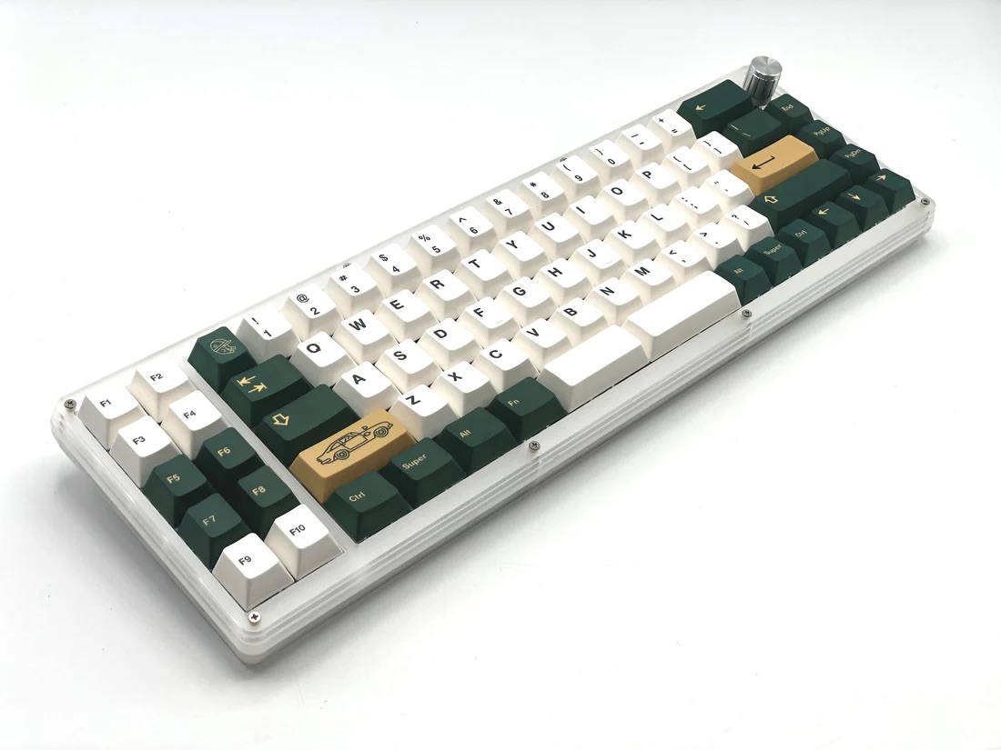
The Convolution keyboard kit is available here: Convolution - 65XT Keyboard Kit
- Included with the Kit
- Convolution PCB
- Acrylic Case
- 8 M2 15mm standoffs
- 3 M2 8mm standoffs (for feet)
- 22 M2 6mm screws
- 4 SKUF feet
- Additional Parts Needed
- MX-compatible switches
- PCB-mount MX Stabilizers - Clip-in or Screw-ins, no Plate-mount
- Rotary Encoder and Knob
- Tools Needed
- Soldering iron
- Solder
- Screwdriver
- Tweezers (for testing PCB)
Build Steps Summary
- Prepare Acrylic Parts
- Test PCB
- Reassemble Bottom Portion of Case
- Add Stabilizers
- Add Rotary Encoders
- Add Switches and Solder
- Continue Case Assembly
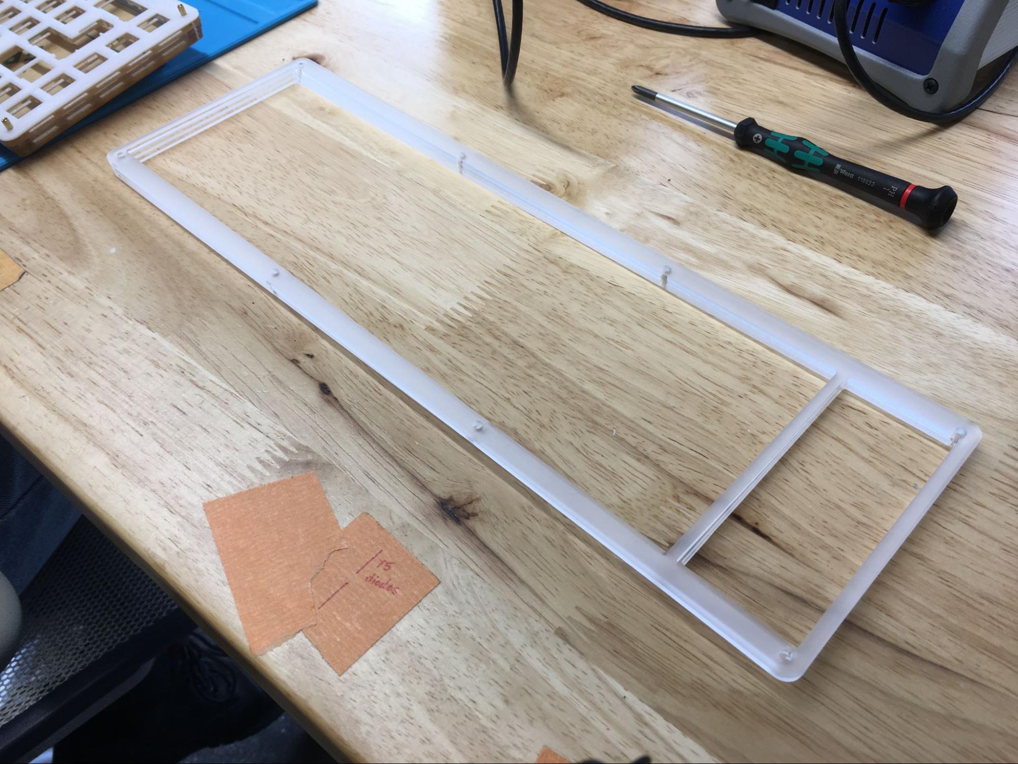
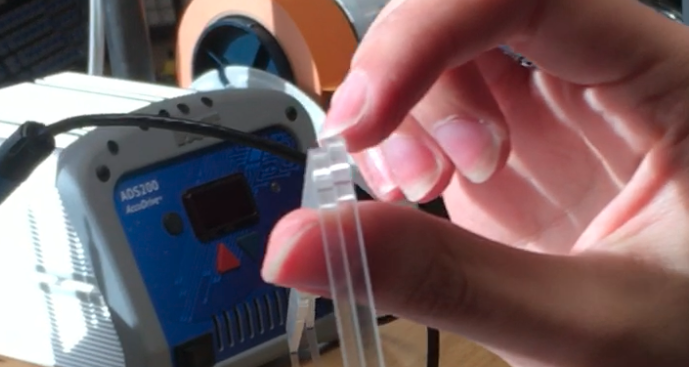
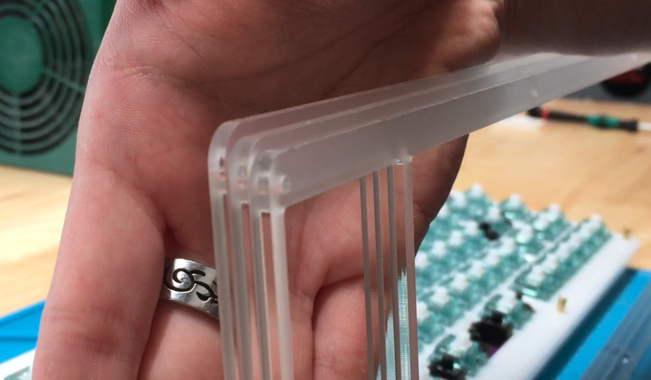
Prepare Acrylic Parts
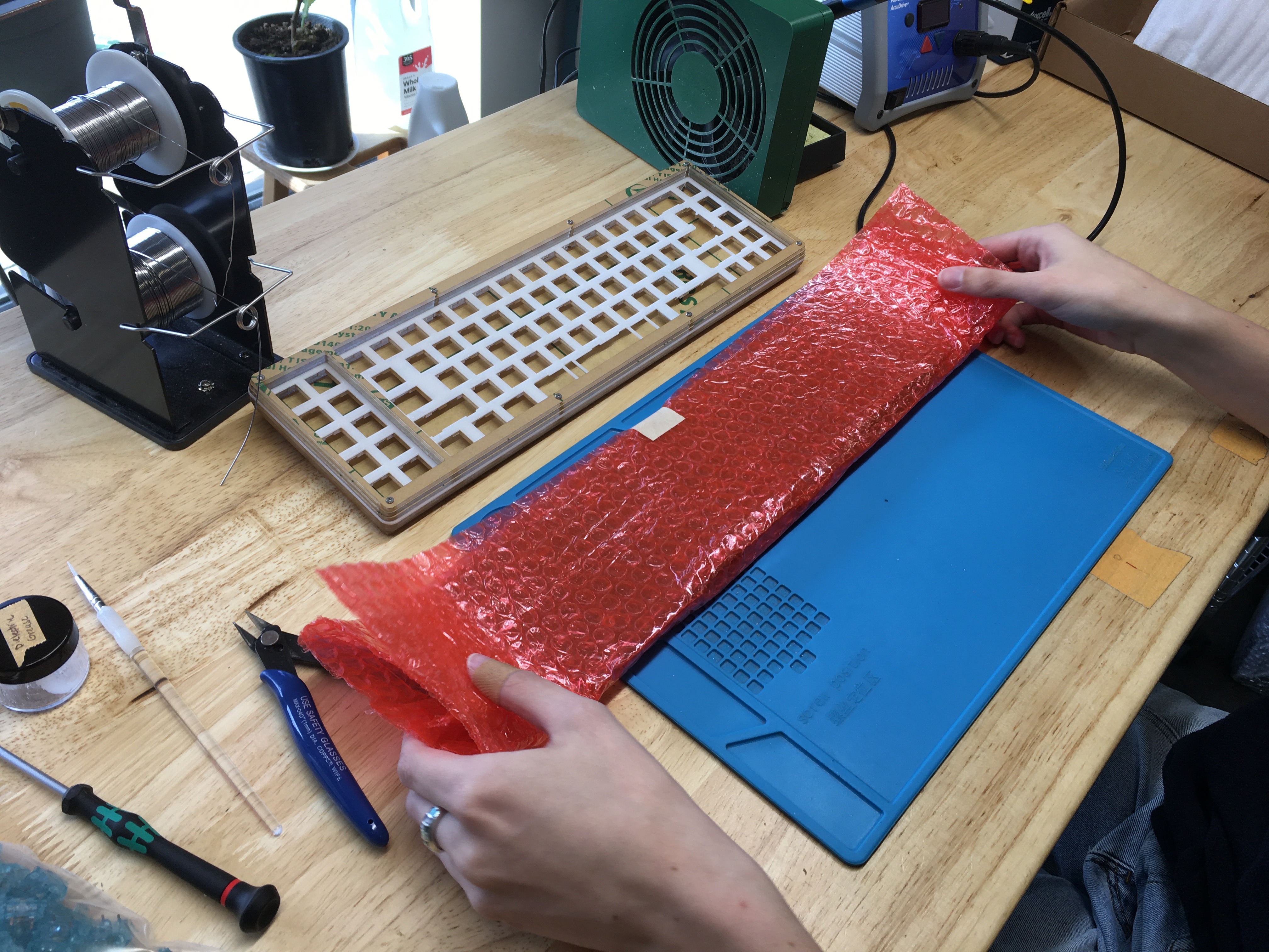
We sent the build assembled for safe travel to you! Now, your first step to your build is actually disassembling everything. Get out a screwdriver to start.
After disassembly, peel off the paper (frosted version) or plastic (black version) from your Convolution case pieces.
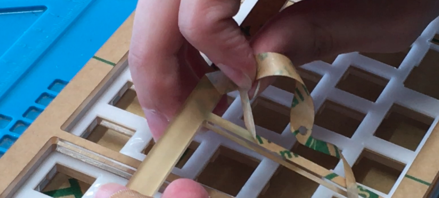
As you peel each layer, it may help to stack them in the same order you peeled them, then it’s just a matter of rebuilding in reverse.
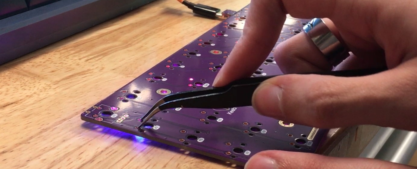
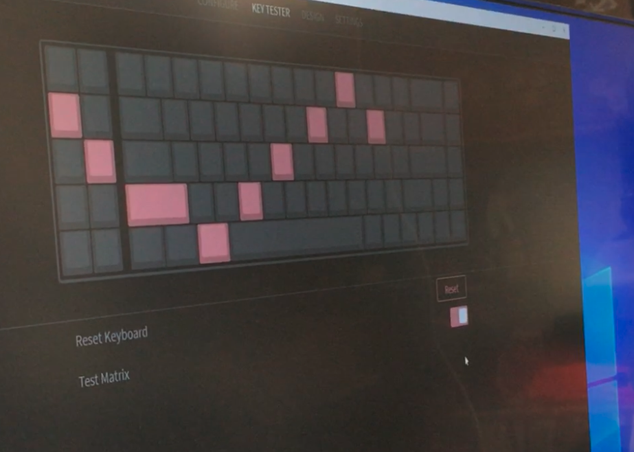
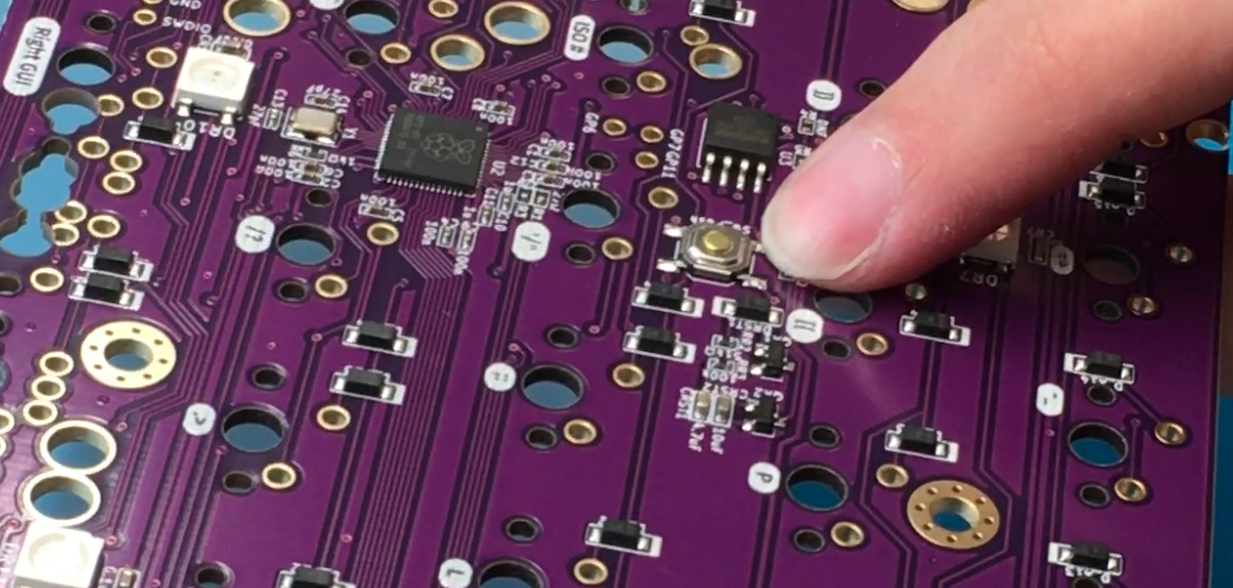
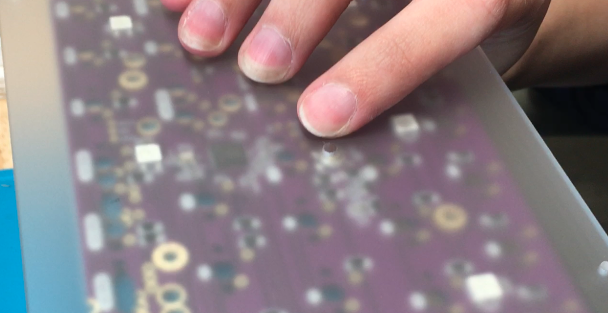
Test PCB
Take a moment to test your PCB before you start assembling!
All the RGBs should light up like this.
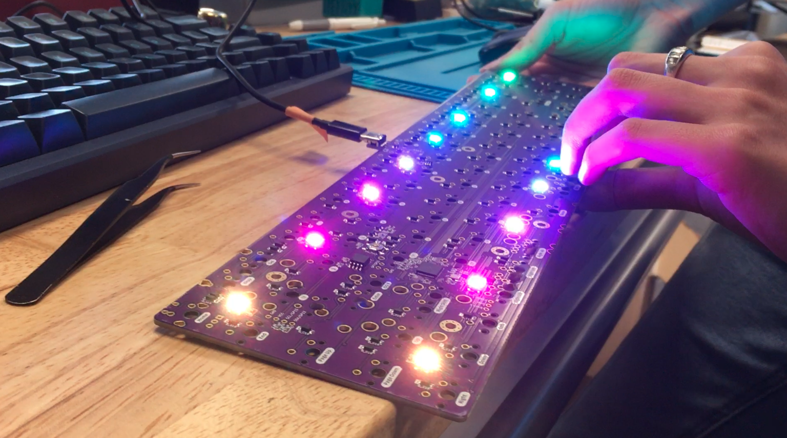
Here's the instructions on testing the PCB: Testing Your PCB
Be sure to test columns and rows, as that will be the biggest tell if anything is not working properly.
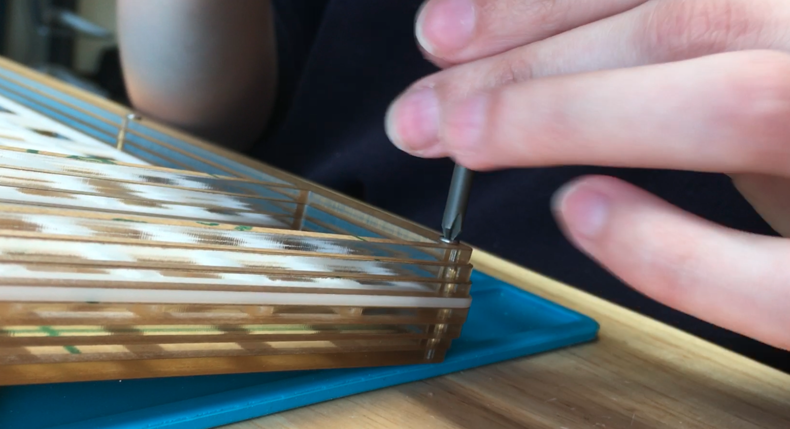
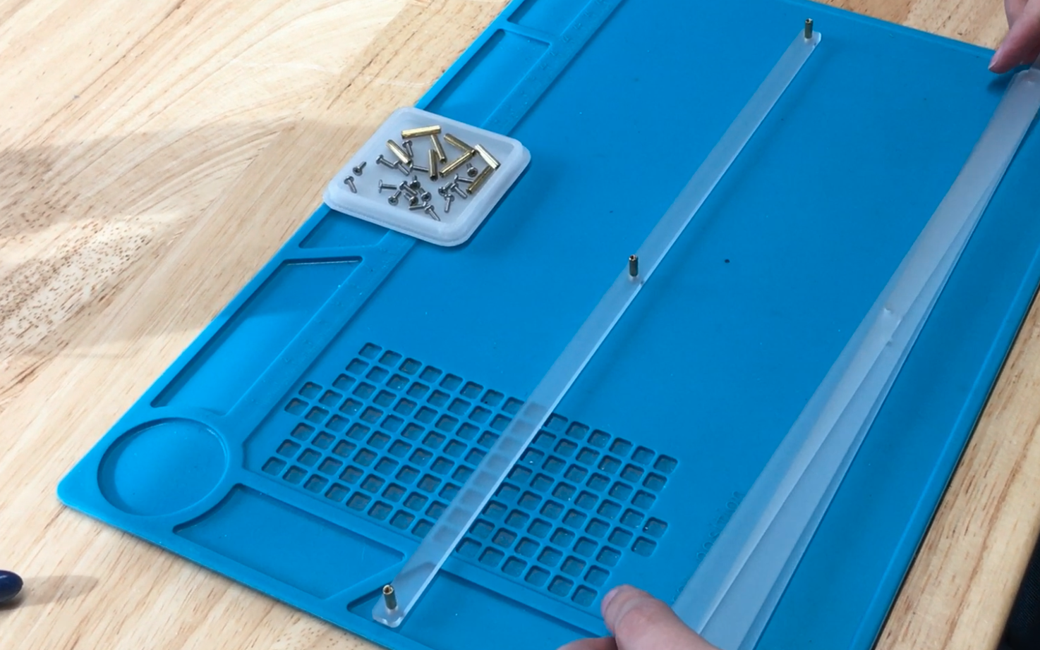
Reassemble Bottom Portion of Case
Assemble Foot Pieces
Here comes the reassembly! Woohoo! Take the smallest piece of the foot and insert a screw and attach a standoff for each hole. Then layer each of the 3 remaining foot pieces on top.
Be sure to use the 8mm standoffs for the feet! The 15mm standoffs are for the main structure of the keyboard.
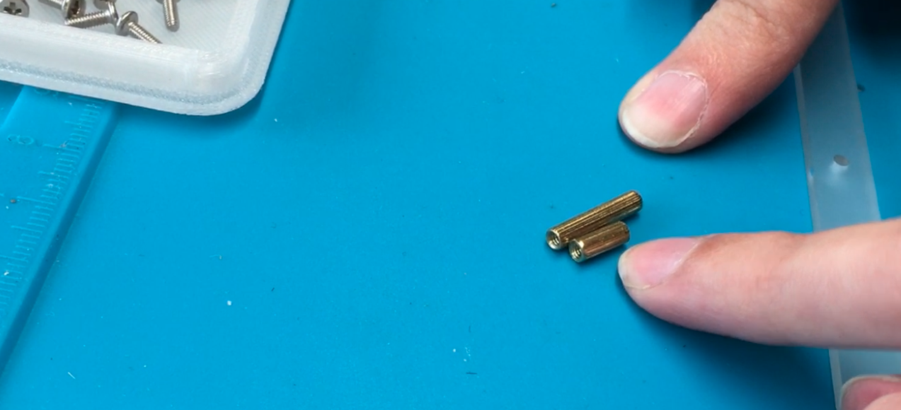
An easy way to tell the smallest part of the foot is seeing which piece has the smallest hole.
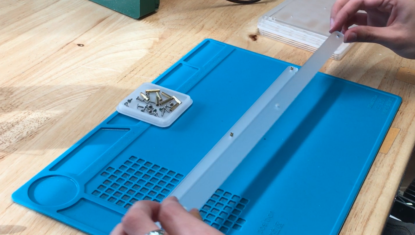
Connect Foot to Bottom Plate
Line up the reset button with the hole in the acrylic.
Now, screw in the foot!
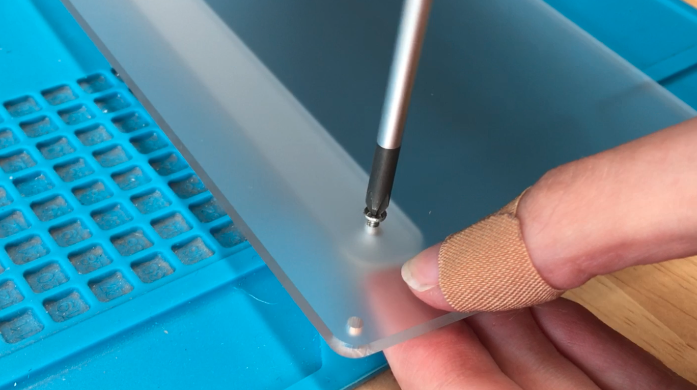
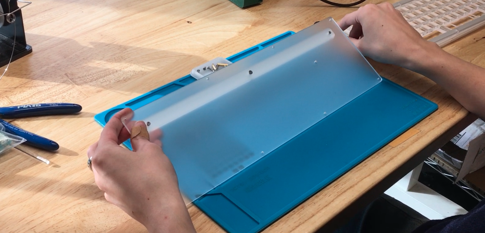
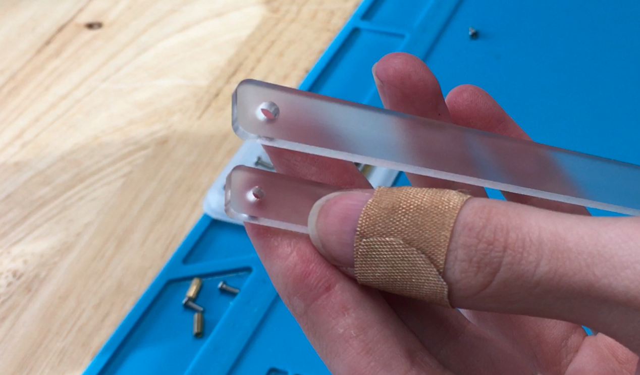
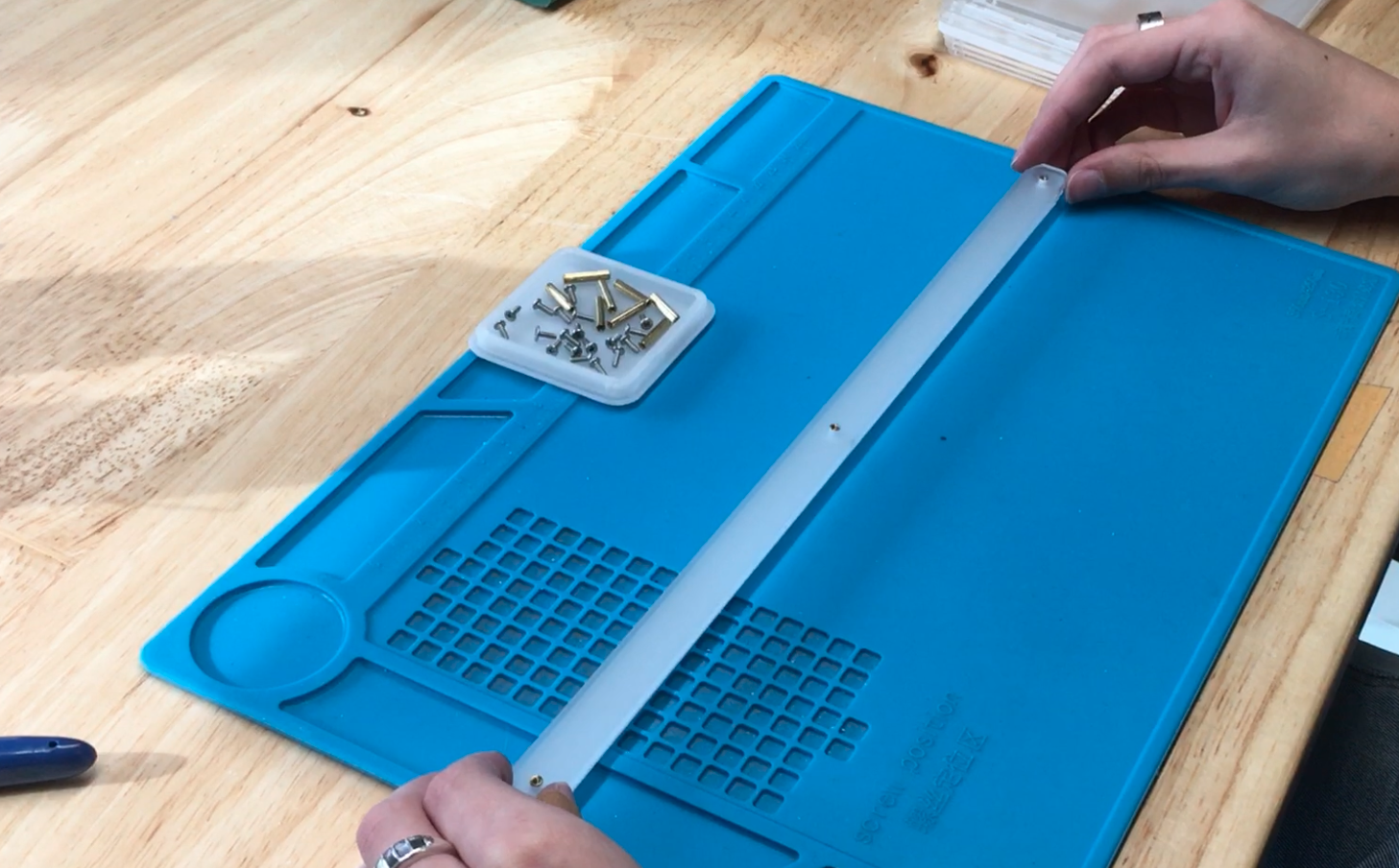
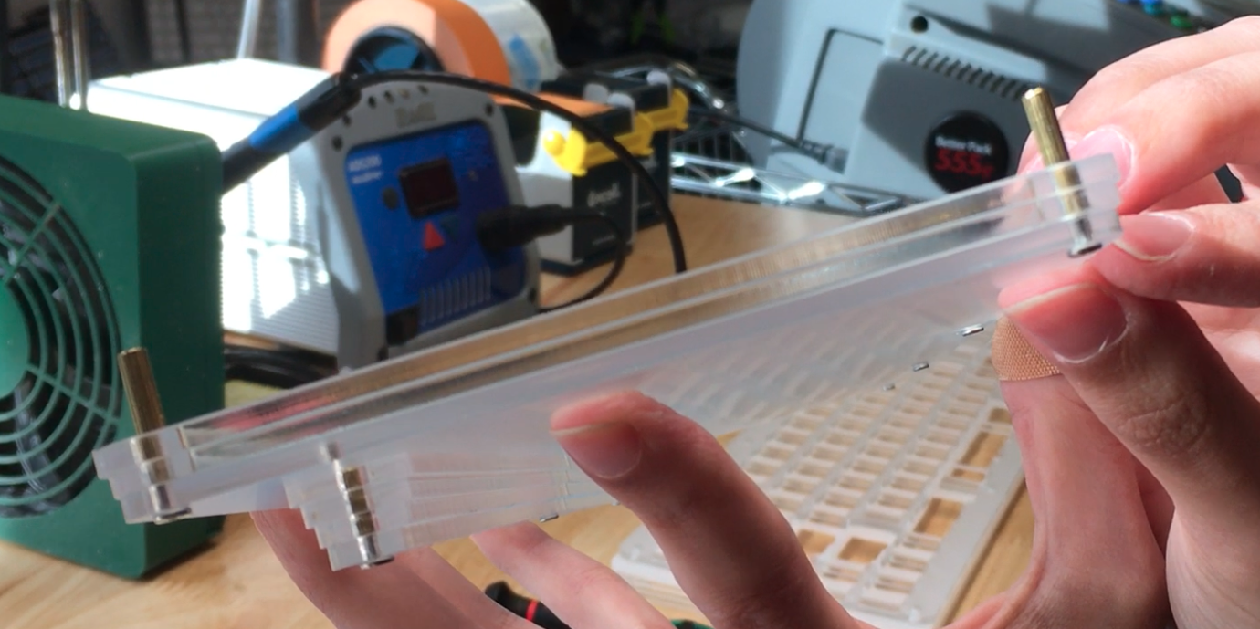
Stack Bottom Layers
Now that the foot is attached, let’s attach the supports for the bottom layer pieces!
Similar to the foot, you’ll attach a screw and standoff for every hole, and then stack layers. Grab the 15mm standoffs and the 6mm flat head screws for this step.
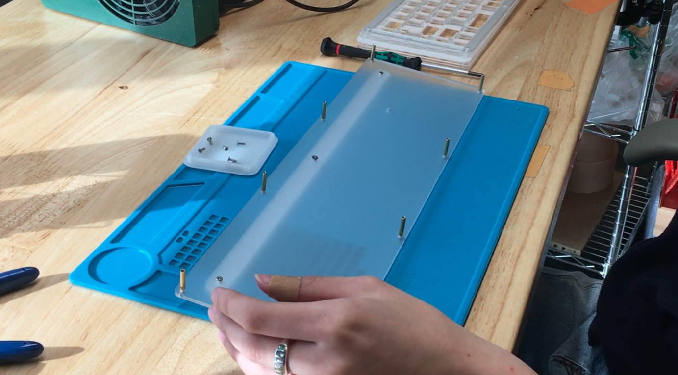
Now grab your next 2 layers. You’ll know you’ve got them in the right order if the small one is on the bottom.
Be sure to have the open slot at the top. It’s above the center screw of the foot.
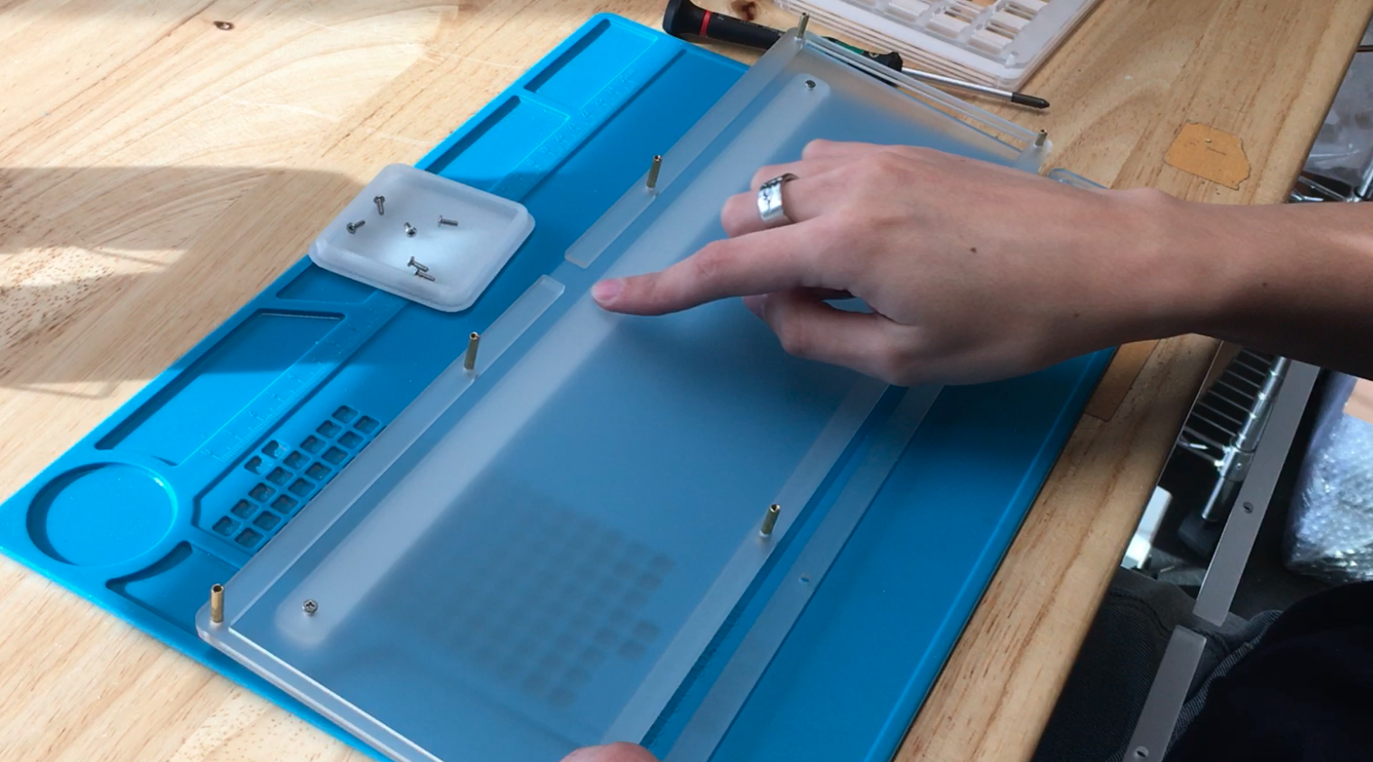
It should look like this: smallest layer on bottom expanding with each layer.
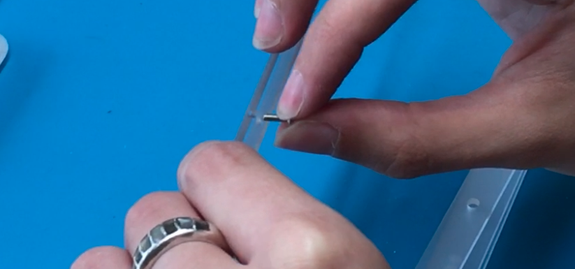
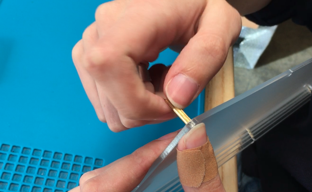
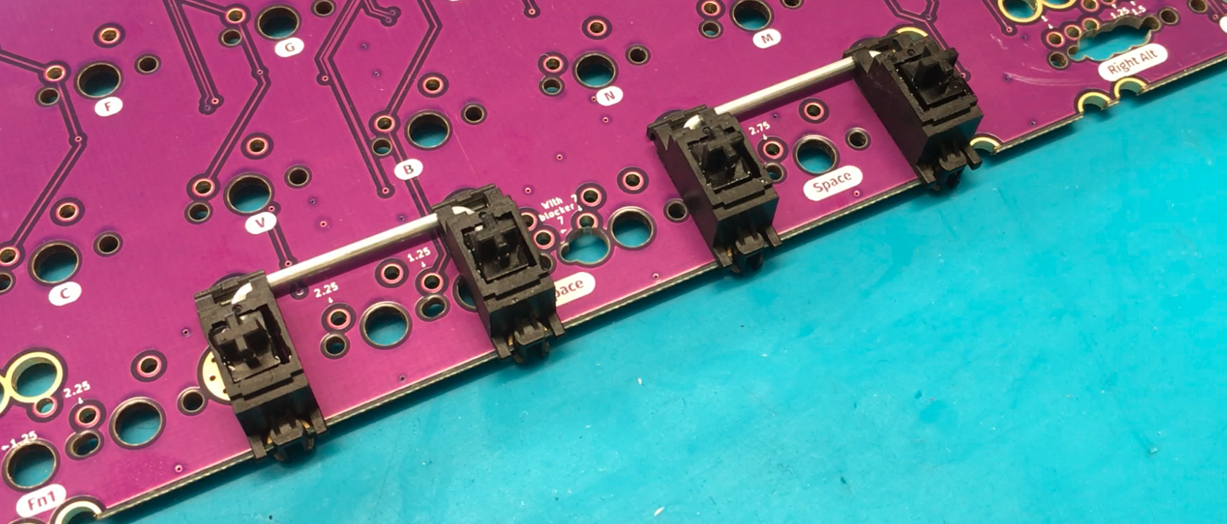
Add Stabilizers
Next, make your stabilizers.
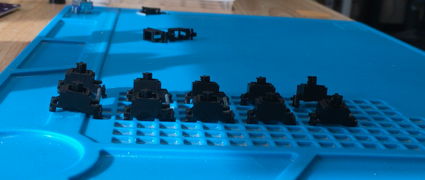
There are a few different ways to place your spacebar stabilizers, but here is the way if you’d like two spacebars.
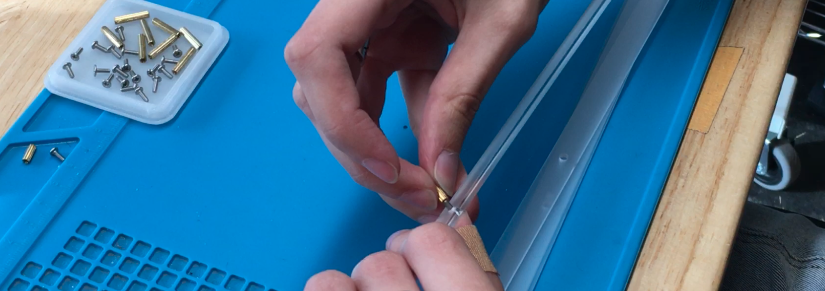
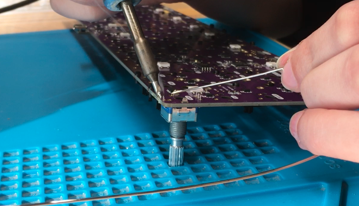
Add Rotary Encoders
Next, if you’d like to have rotary encoders, now is the time to solder them on. The rotary encoder(s) must be present before putting the switch plate down.
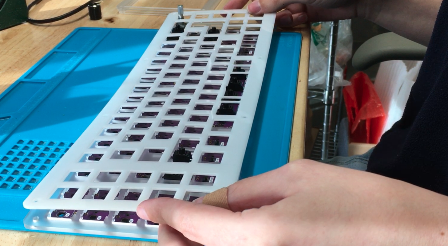
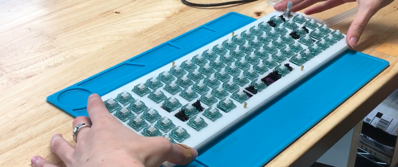
Add Switches and Solder
Setup Support Layer and Switch Plate
Next, add the acrylic support layer (frosted or black depending on your build) that will go in between the PCB and the switch plate.
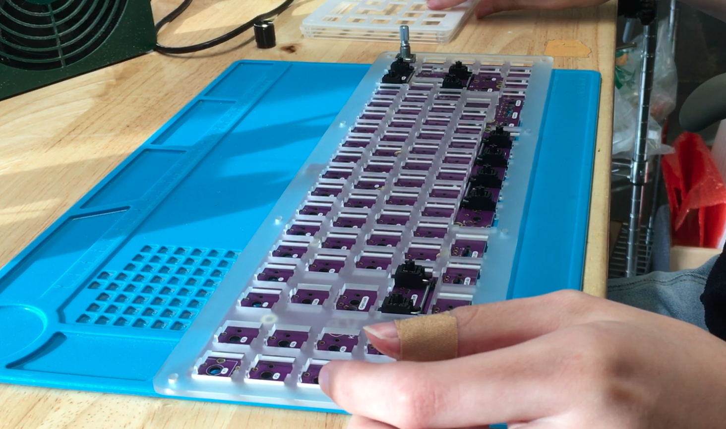
Then the thinner flexible piece over that, which is the switch plate.
It is recommended that you test each of your stabilizers before adding switches and beginning to solder. That way, you’re sure everything is working prior to solder! 🙂
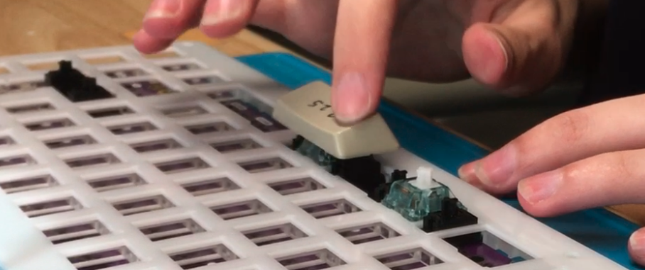
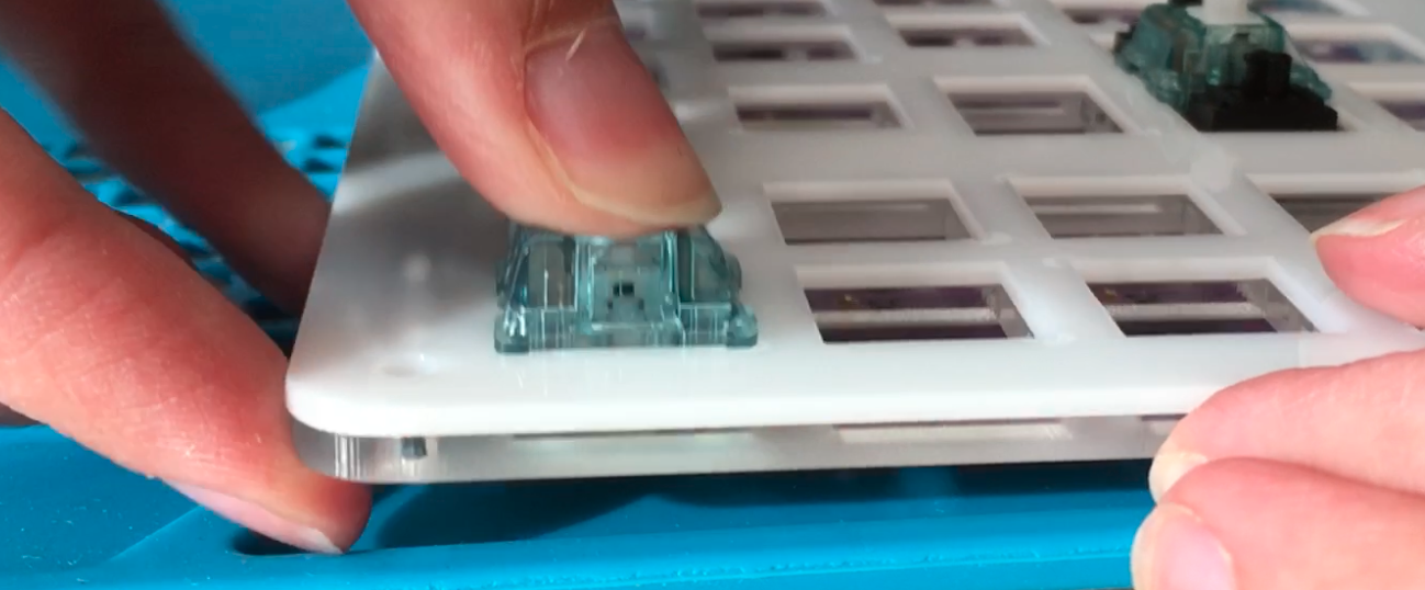
Insert Switches
When pushing in the rest of your switches, be sure that you hear a click, so you know it’s fully settled into its slot.
It’s a good idea to solder a switch at each of the corners and make sure everything is still snug in place.
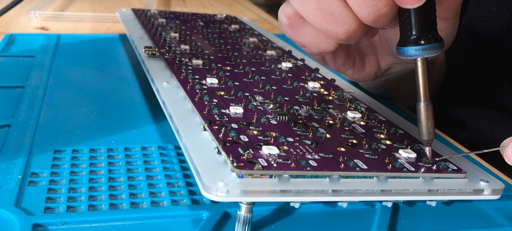
Place your soldered PCB on top of the standoffs. Almost done!
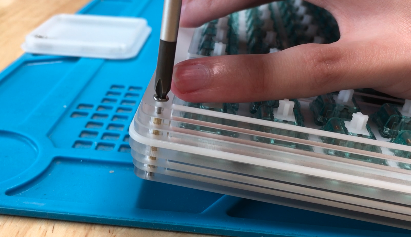
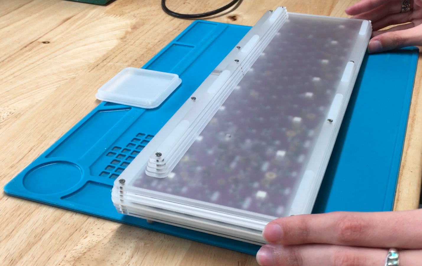
Continue Case Assembly
Stack Top Pieces
The three top pieces are all that remain! You know they’re in order if the layer closest to the PCB is the biggest.
You’ll know the top piece by the holes for it being the smallest of the three.

Now, all that’s left is to tighten the top screws down.
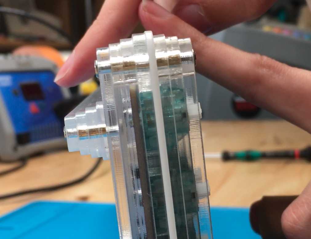
It should look like this from the side when you’re done!
Add SKUF Feet
SKUF feet can go anywhere you like, but this arrangement we found works really well.
Enjoy!