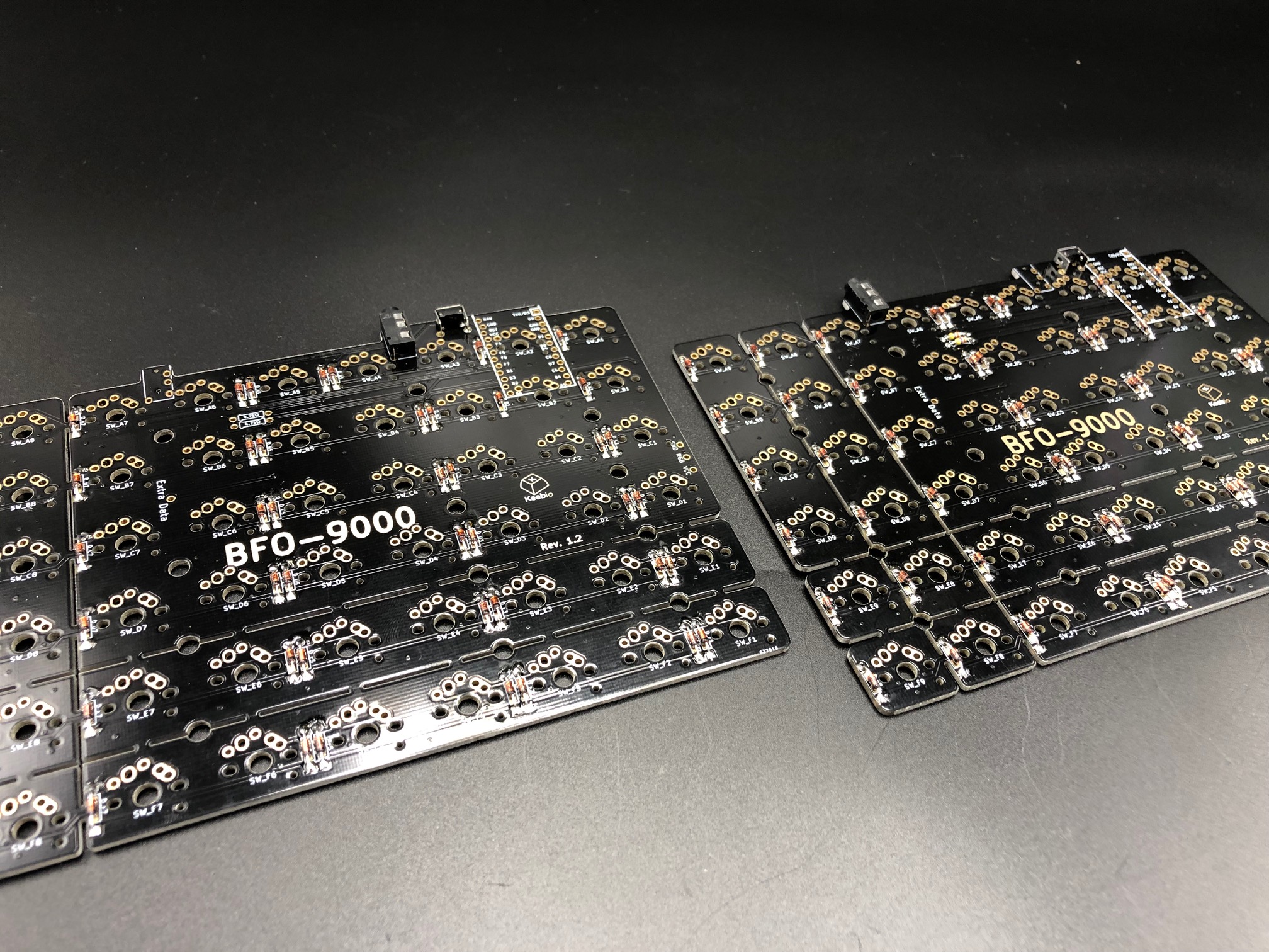
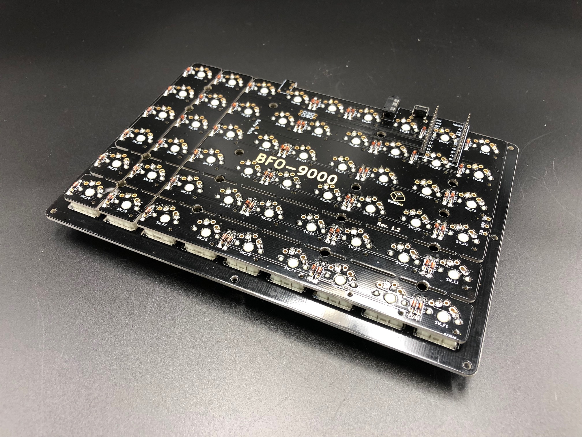
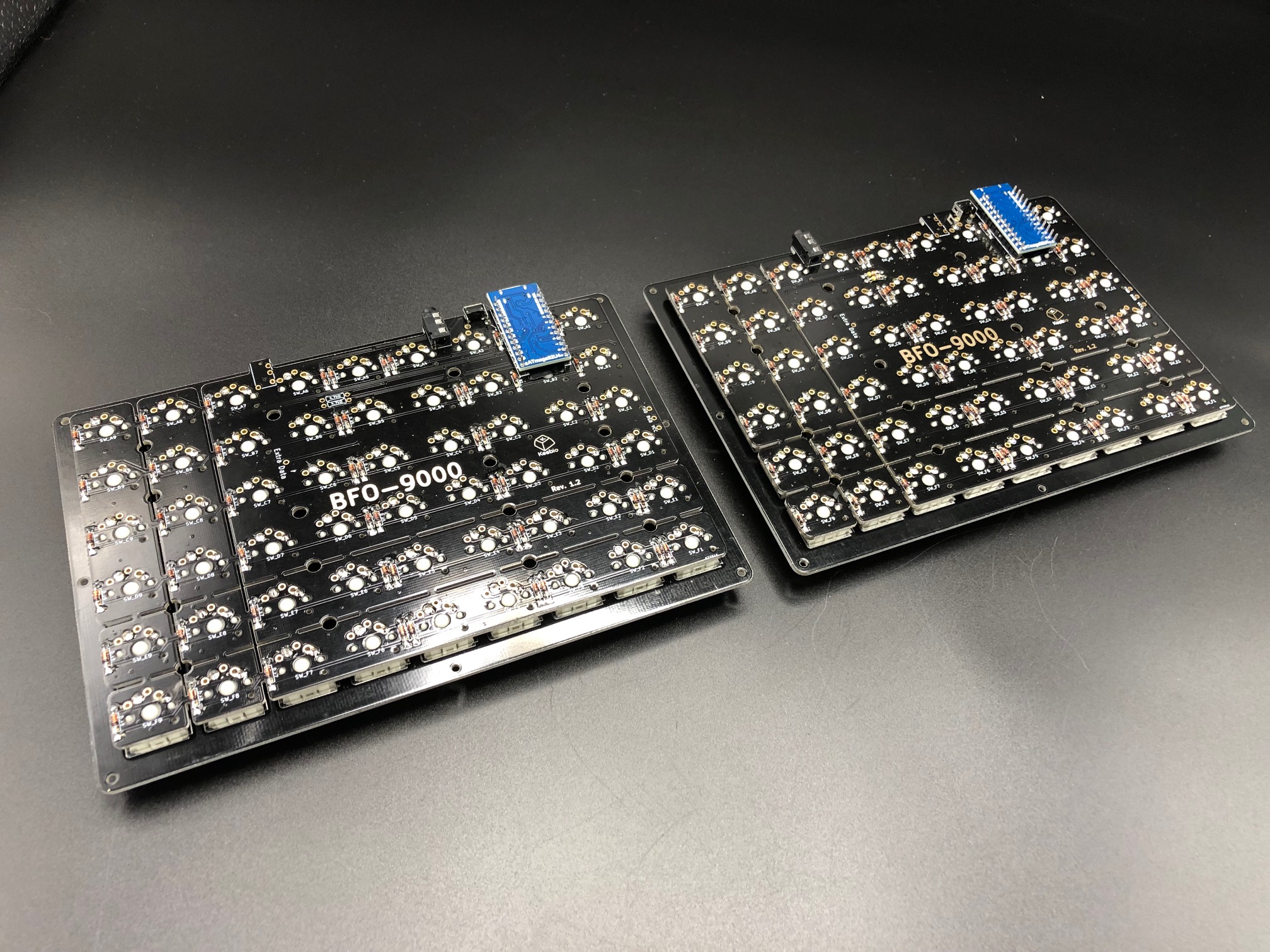
BFO-9000
Parts List
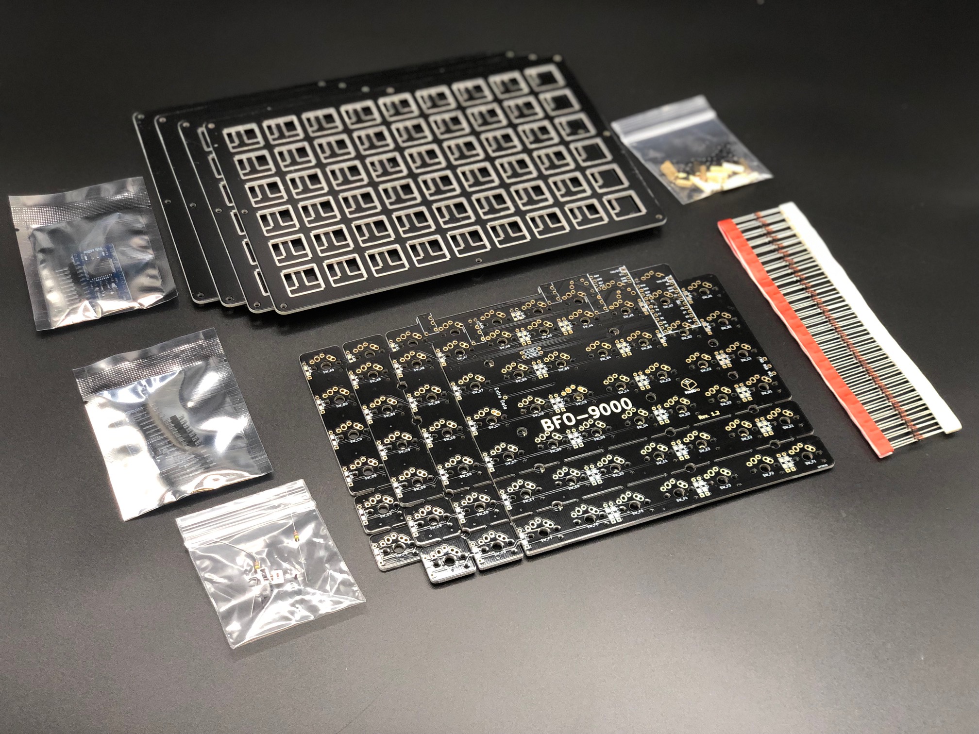
Here's a list of parts needed for the build:
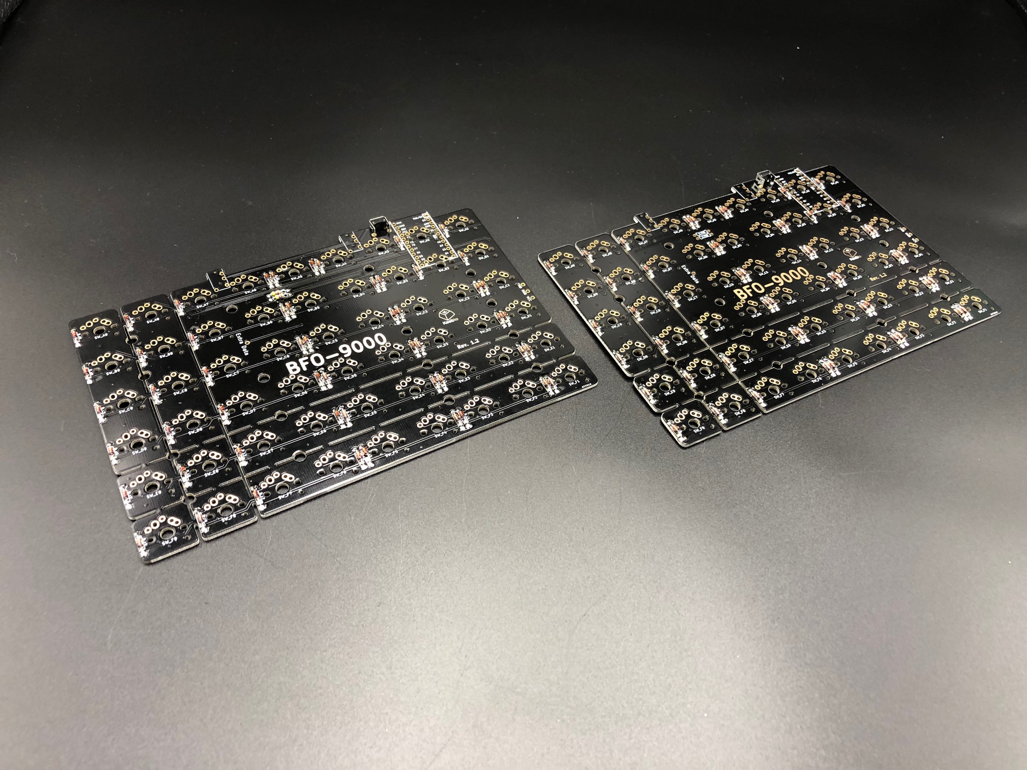
- BFO-9000 PCBs
- BFO-9000 Plates
- 1 TRRS cable
- 2 Pro Micro-compatible Microcontrollers (you may mix-and-match controllers)
- Arduino Pro Micro
- Elite-C
- Elite-Pi (can't mix-and-match these)
- Up to 108 switches (MX-compatible, Alps, and Choc switches are supported)
Build Steps
Here's a summary of the build steps:
- Prepare components
- Solder components
- Solder diodes
- Solder I2C resistors (optional)
- Solder push button and TRRS jack
- Solder Pro Micro header pins
- Add switches to switch plate
- Solder switches
- Flash Pro Micros
- Solder Pro Micros
- Solder RGB strip (optional)
- Assemble case
- Insert standoffs into middle layer (optional)
- Screw standoffs into switch plate
- Attach bottom plate using screws
Rev. 1.3-1.5 PCBs
If you've got the version of BFO-9000 PCBs with pre-soldered components (diodes, TRRS jacks, reset button, resistors), then you can skip ahead to soldering on microcontroller headers.

Both of the TRRS jacks on each PCB of this revision are connected to each other, so you may use either jack when connecting both halves together.
Prepare components
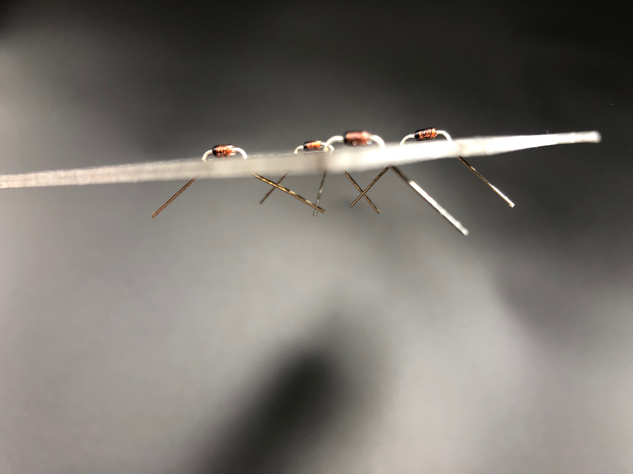
Bend the diodes, first technique, bend them around your finger:
Second technique for bending diodes is to do it around a stack of plates:
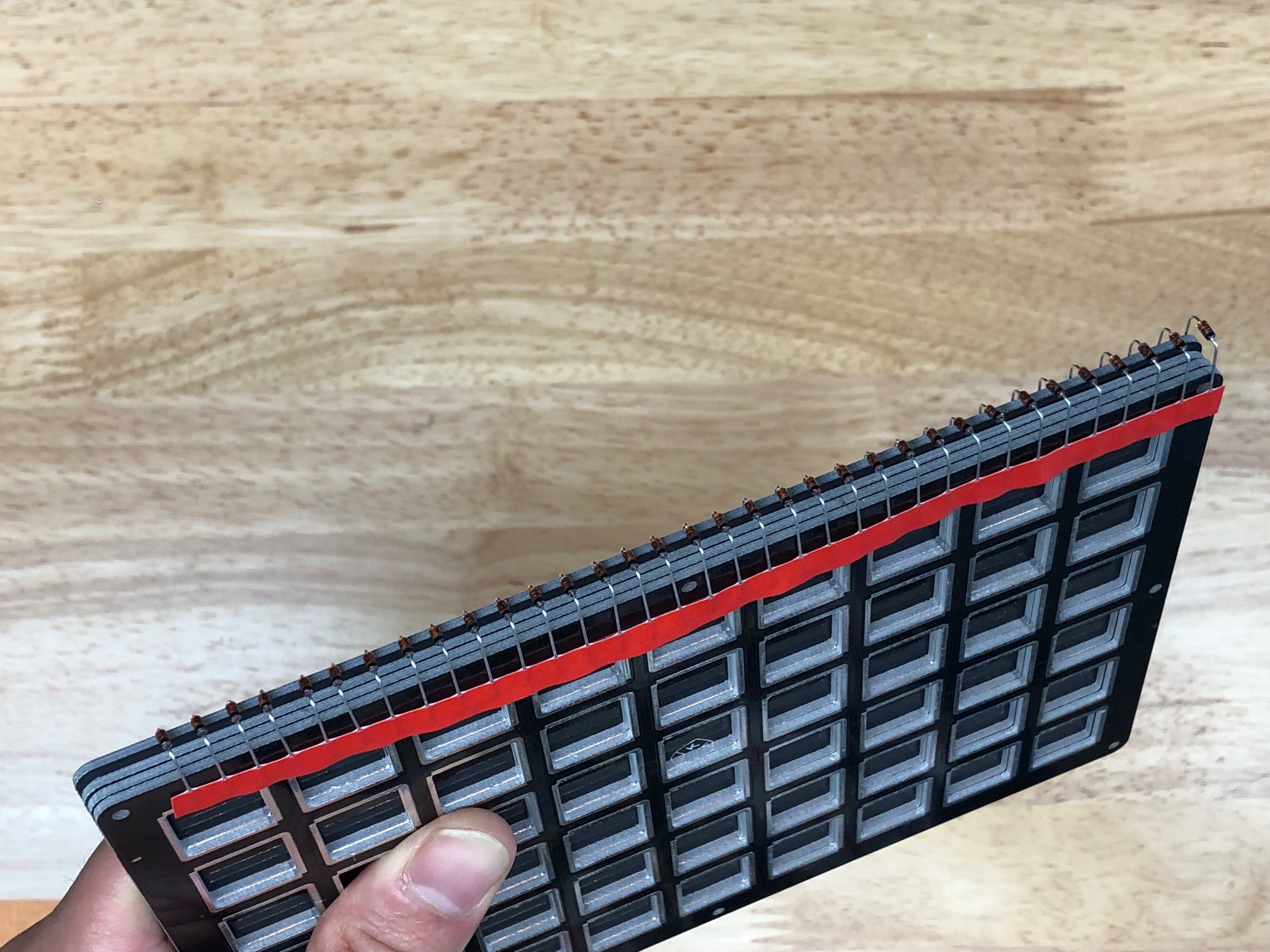
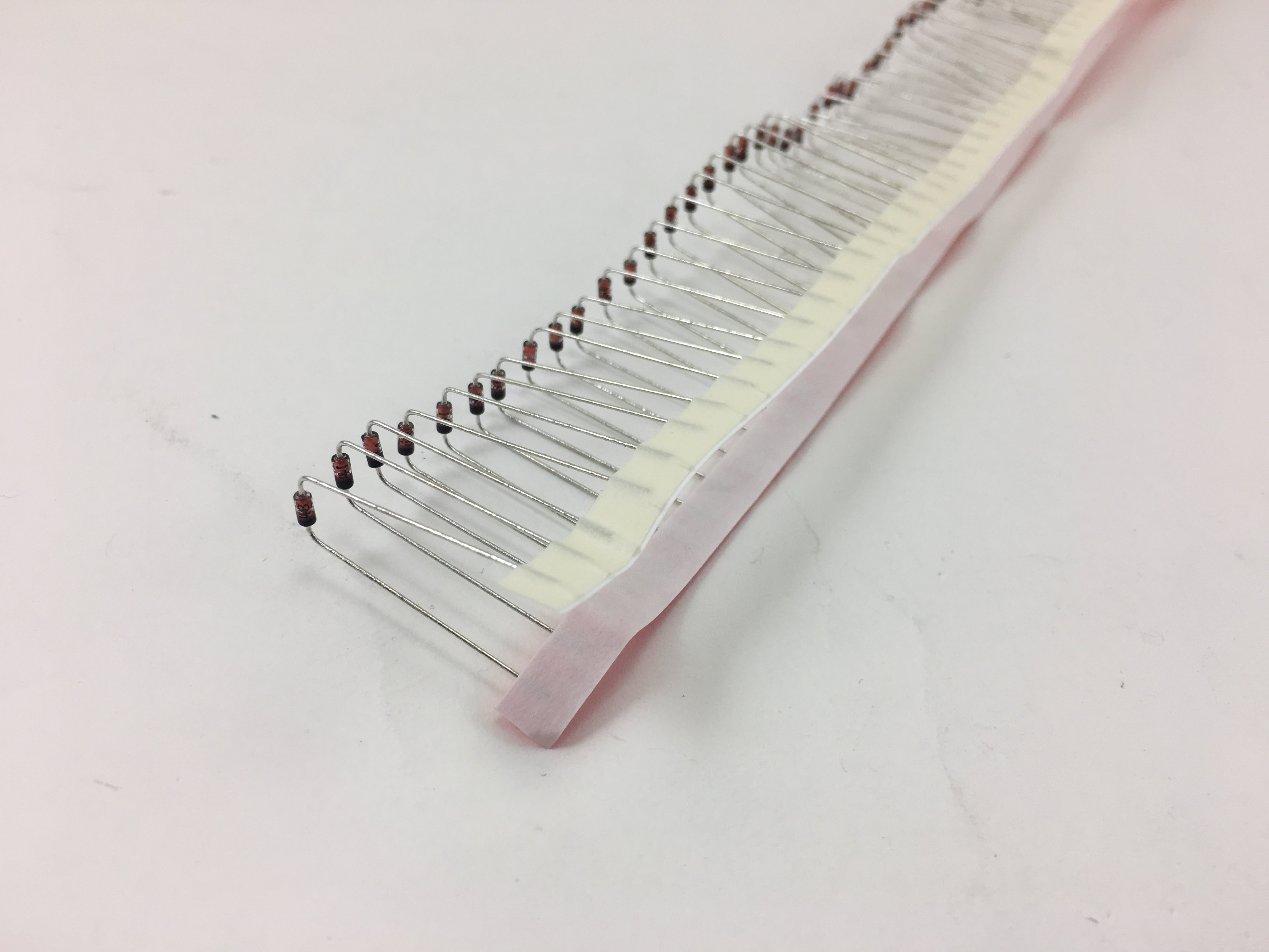
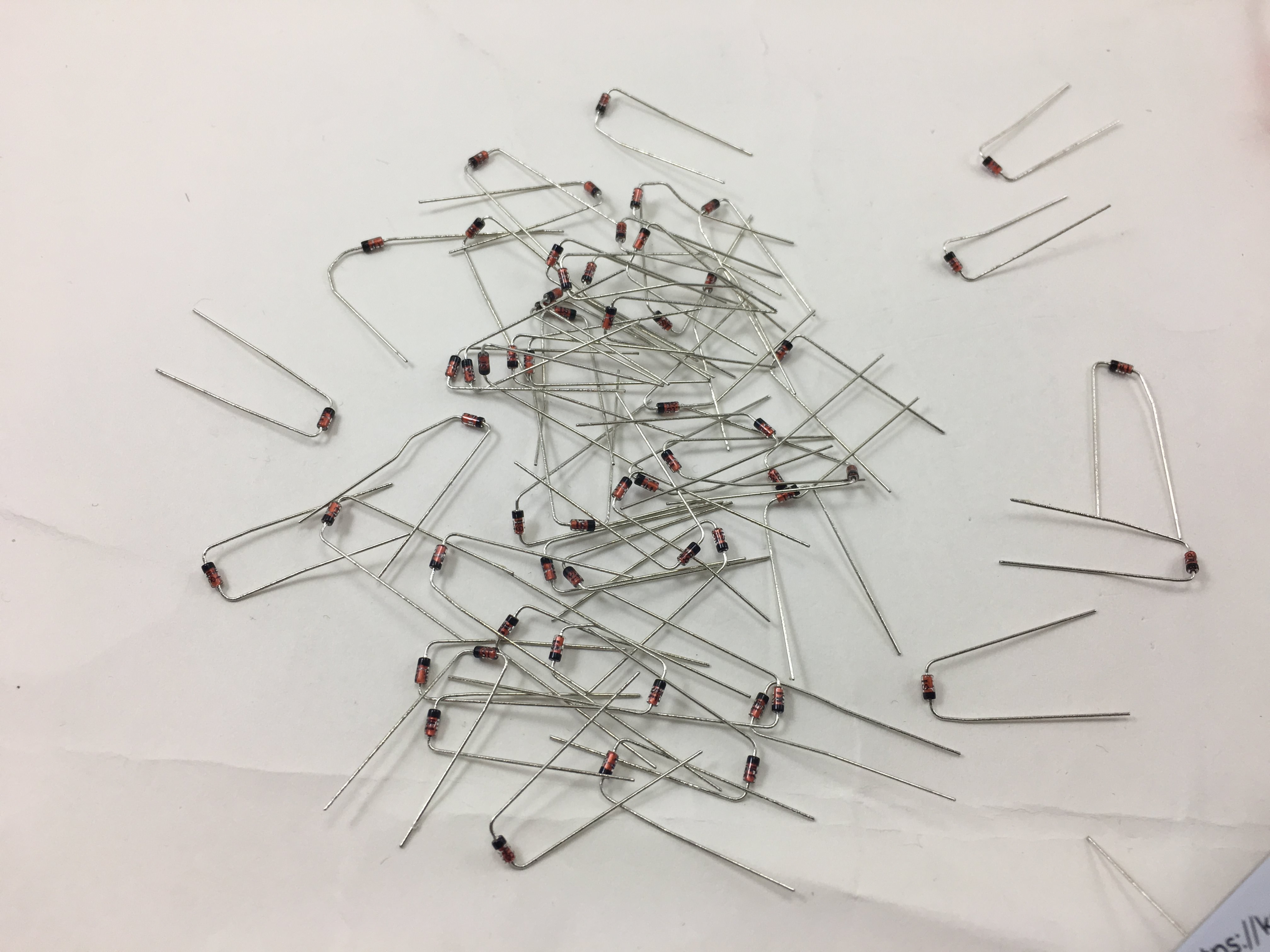
Strip of diodes bent now:
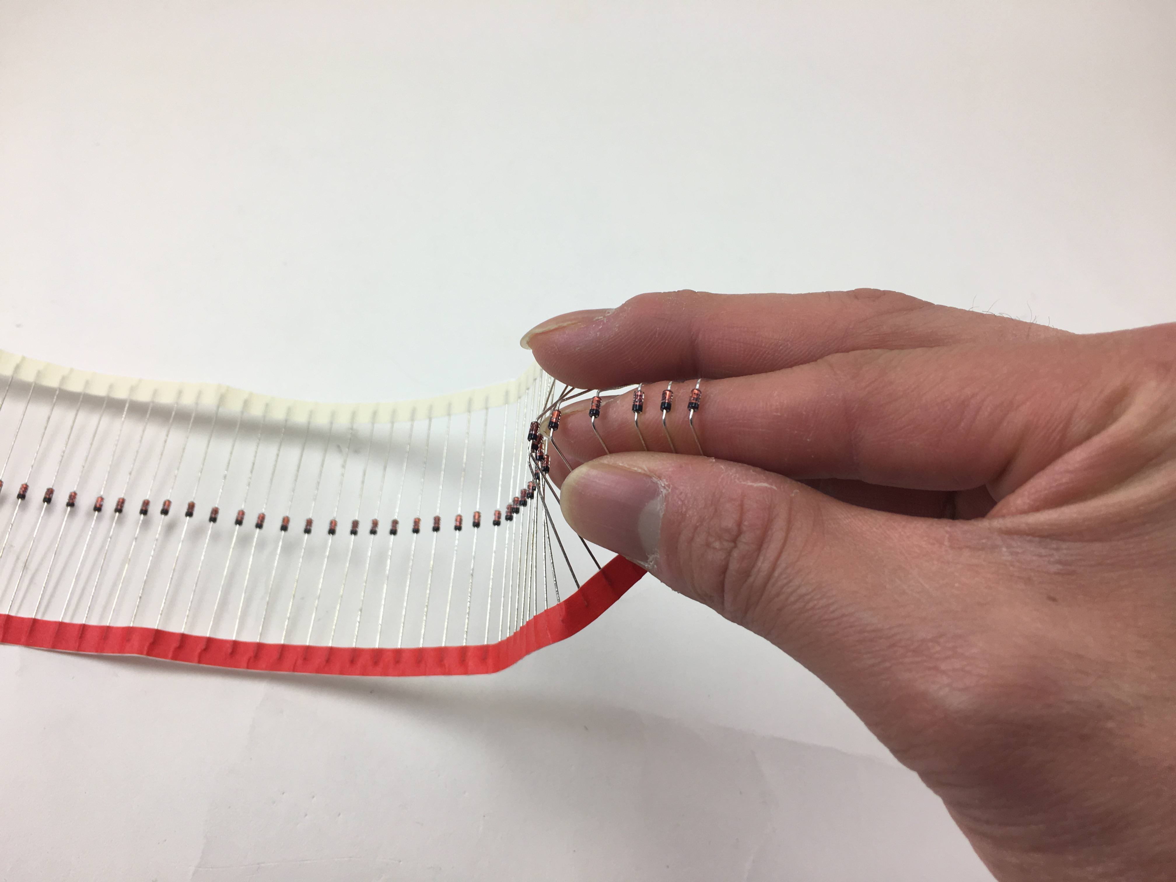
Ripping off the paper holding all the resistors together. Grip the diodes tightly so they don't bend as you're ripping the paper off.
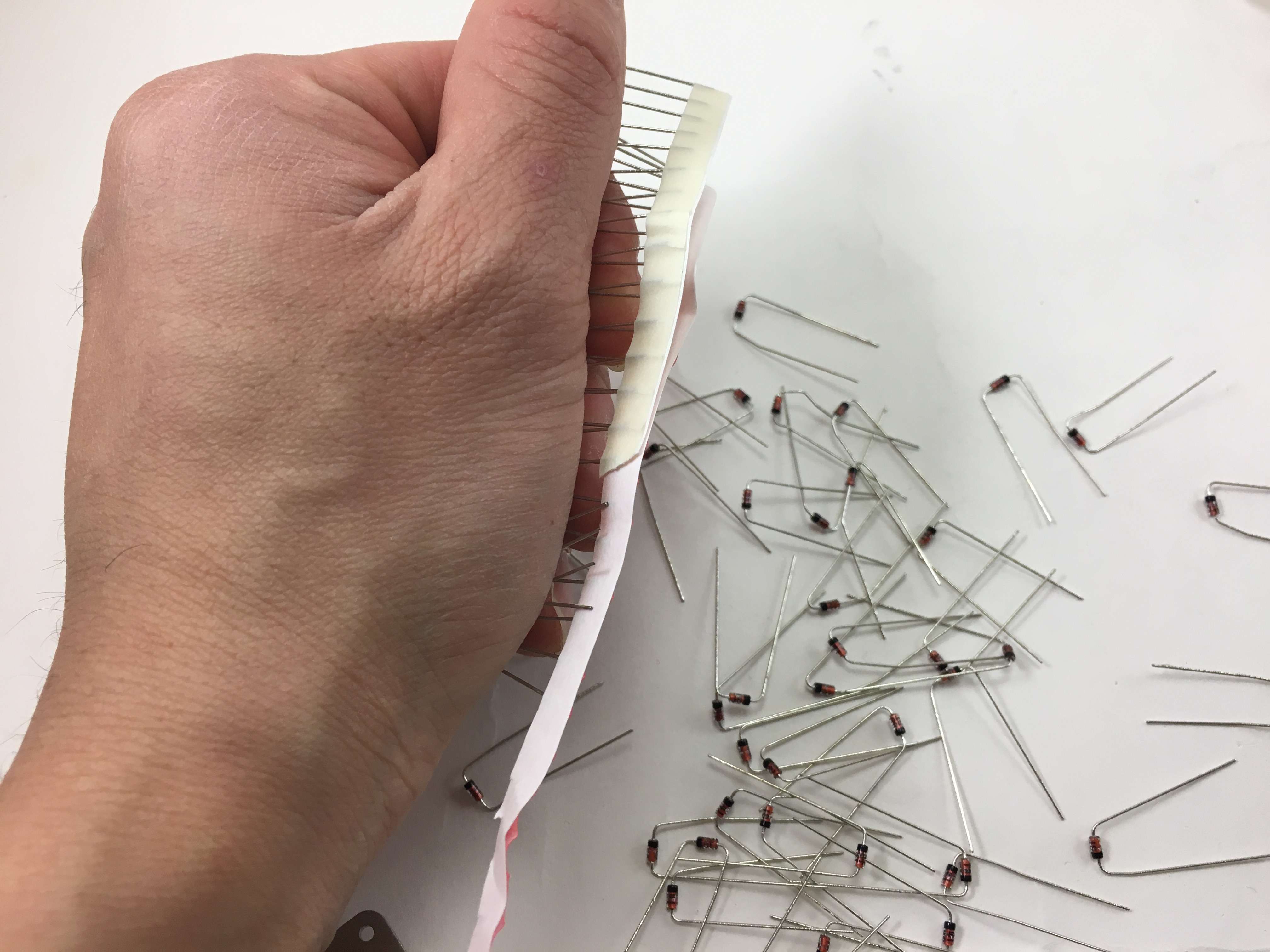
All separated from the paper, ready for insertion into PCB:
Solder Components
The diodes, resistors, push buttons, TRRS jacks, and Pro Micro header pins can be soldered in any order.
Note that the two halves of the PCBs are identical. The only difference for each half is that you will place the TRRS jacks in different locations (towards the middle of the board).
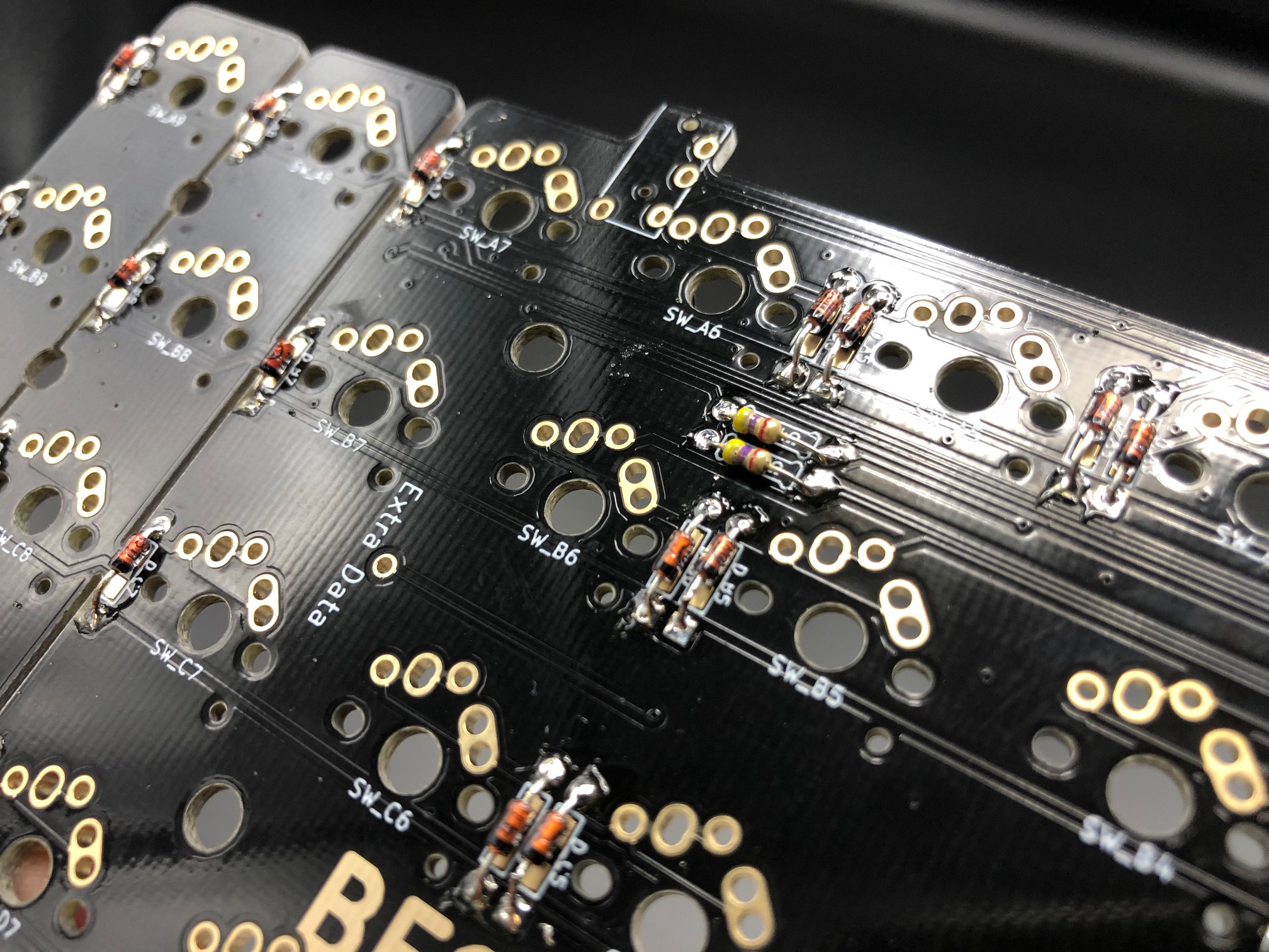
Add diodes
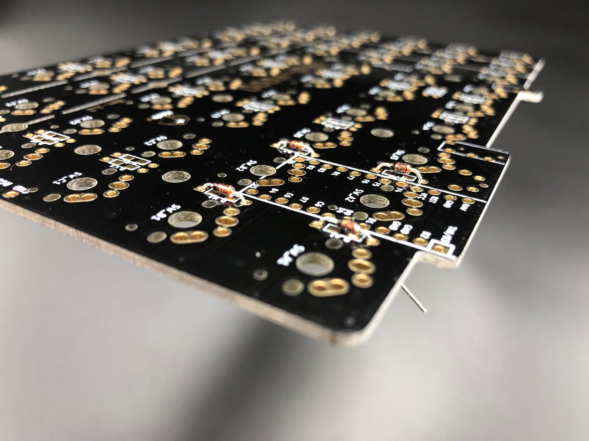
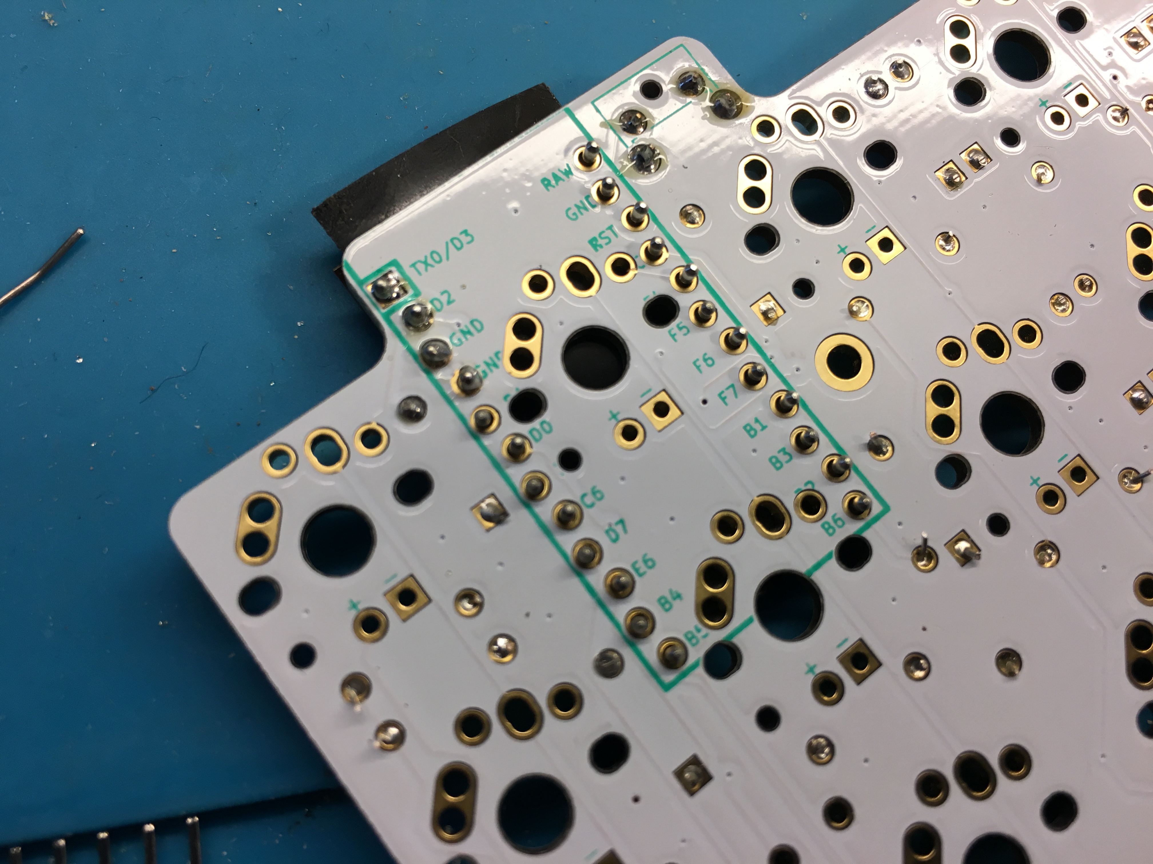
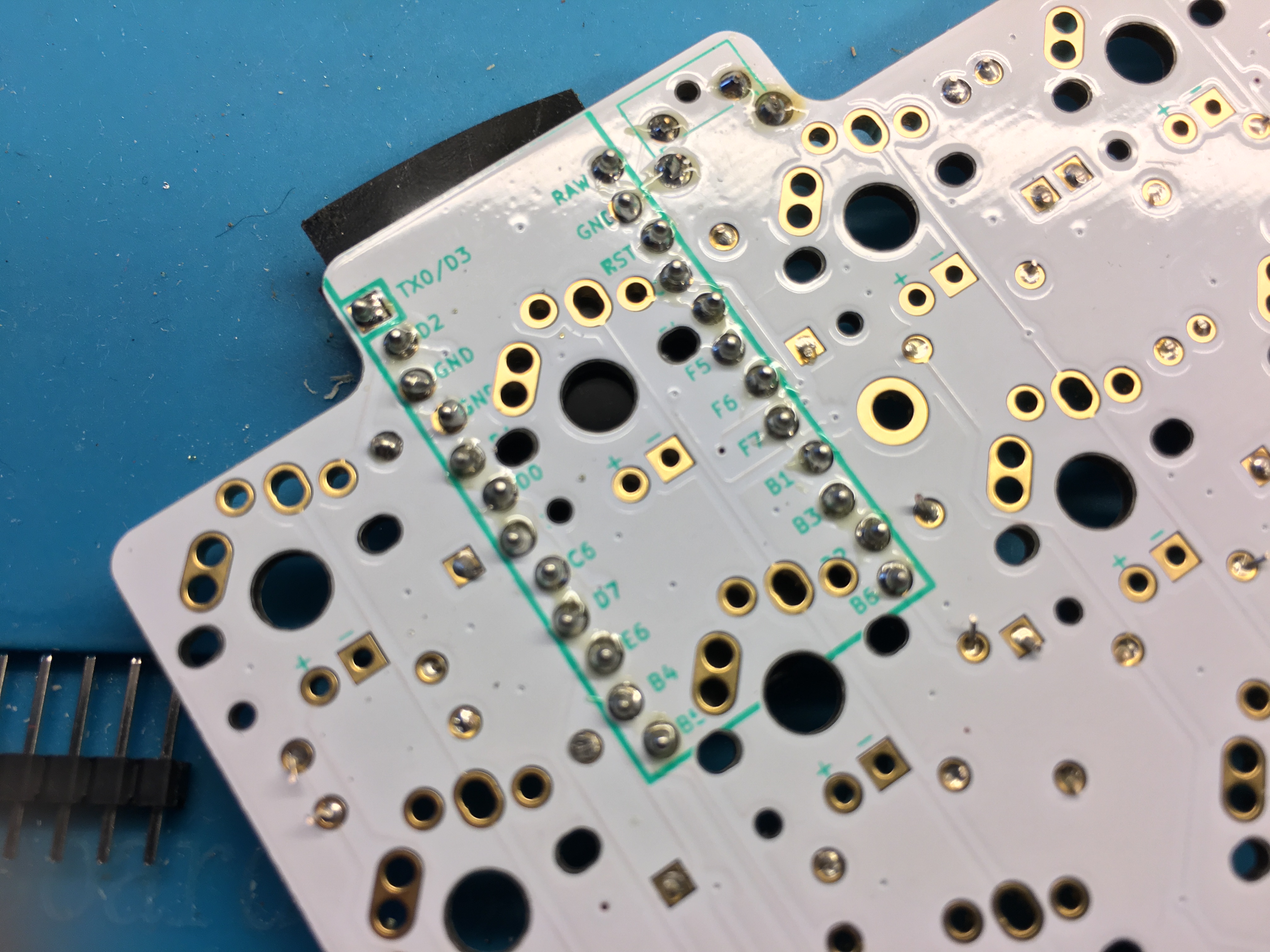
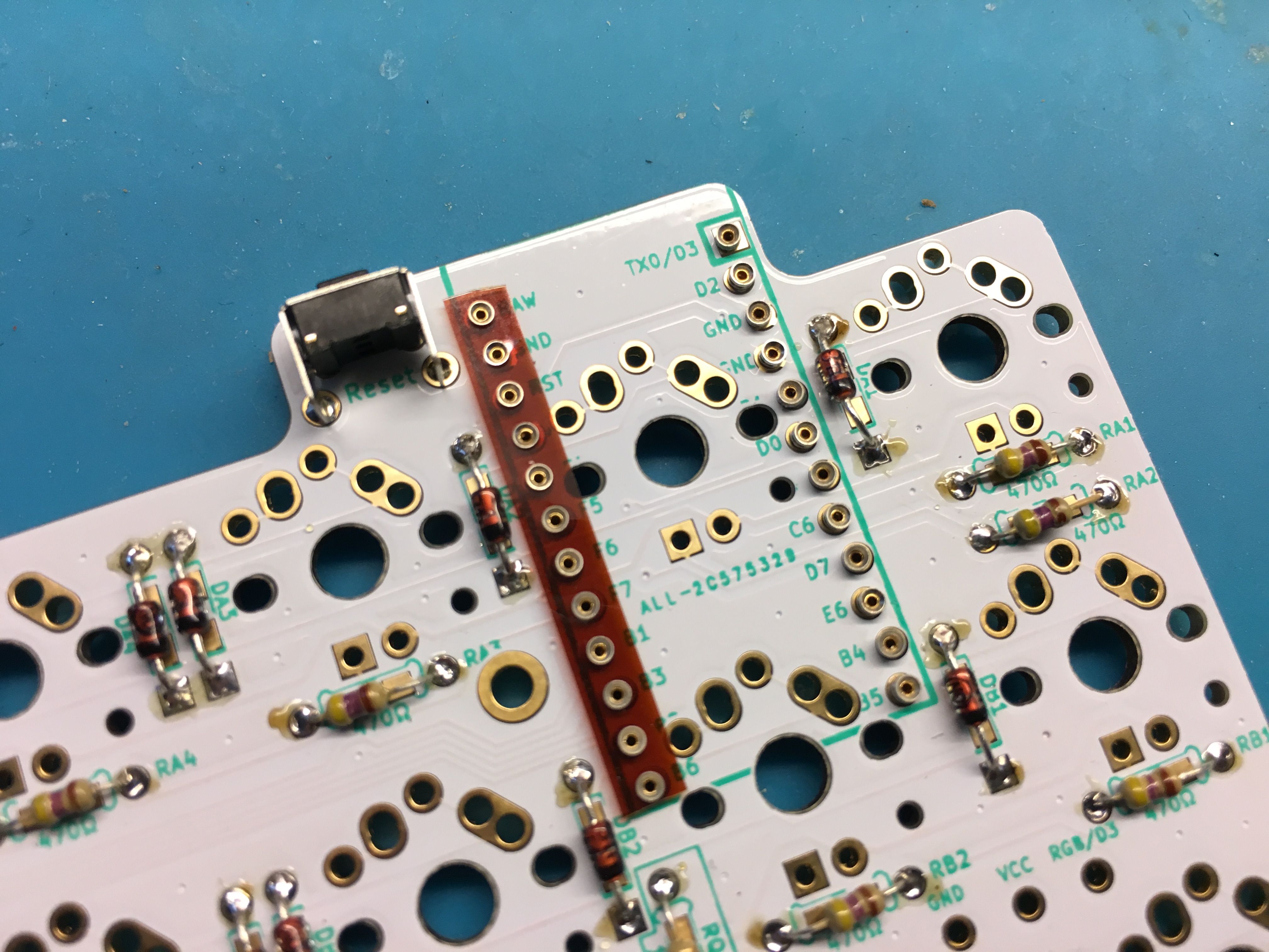
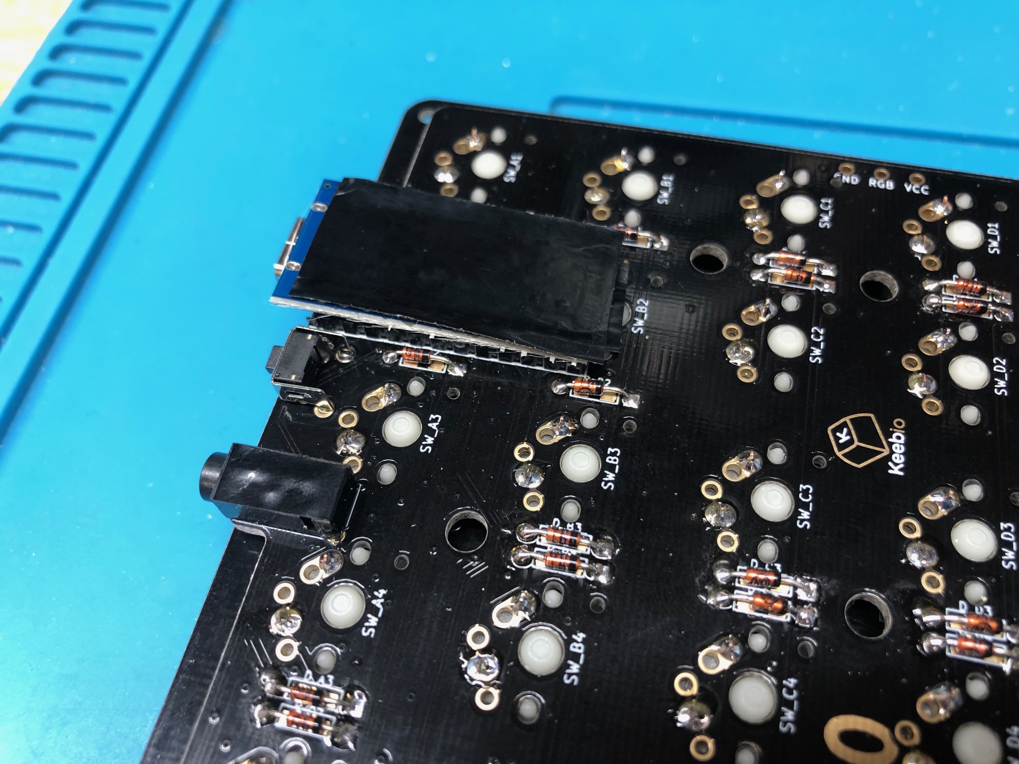
On the bottom side of the PCB, insert diodes with the black line towards the bottom. Square = Black line. All of the diodes are oriented vertically on the PCB:
Sticking the diodes on the top side of the PCB is not recommended, because you can't replace them once everything is assembled using that method.
Bend the legs out to hold the diodes in place for when you solder them in:
Solder the diodes and clip the diode legs off:

Add I2C resistors (optional)
Add the I2C resistors to the left PCB, orientation does not matter for resistors:
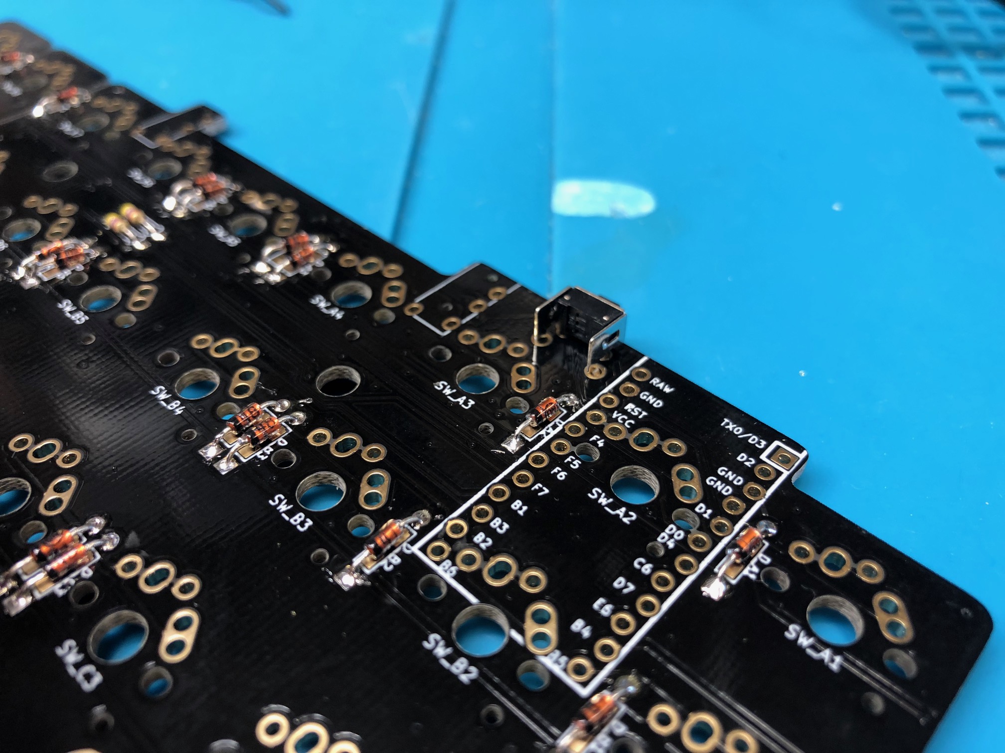
Add TRRS jack and reset button
Add the reset button to the PCB:
Flip the board over and solder reset button:
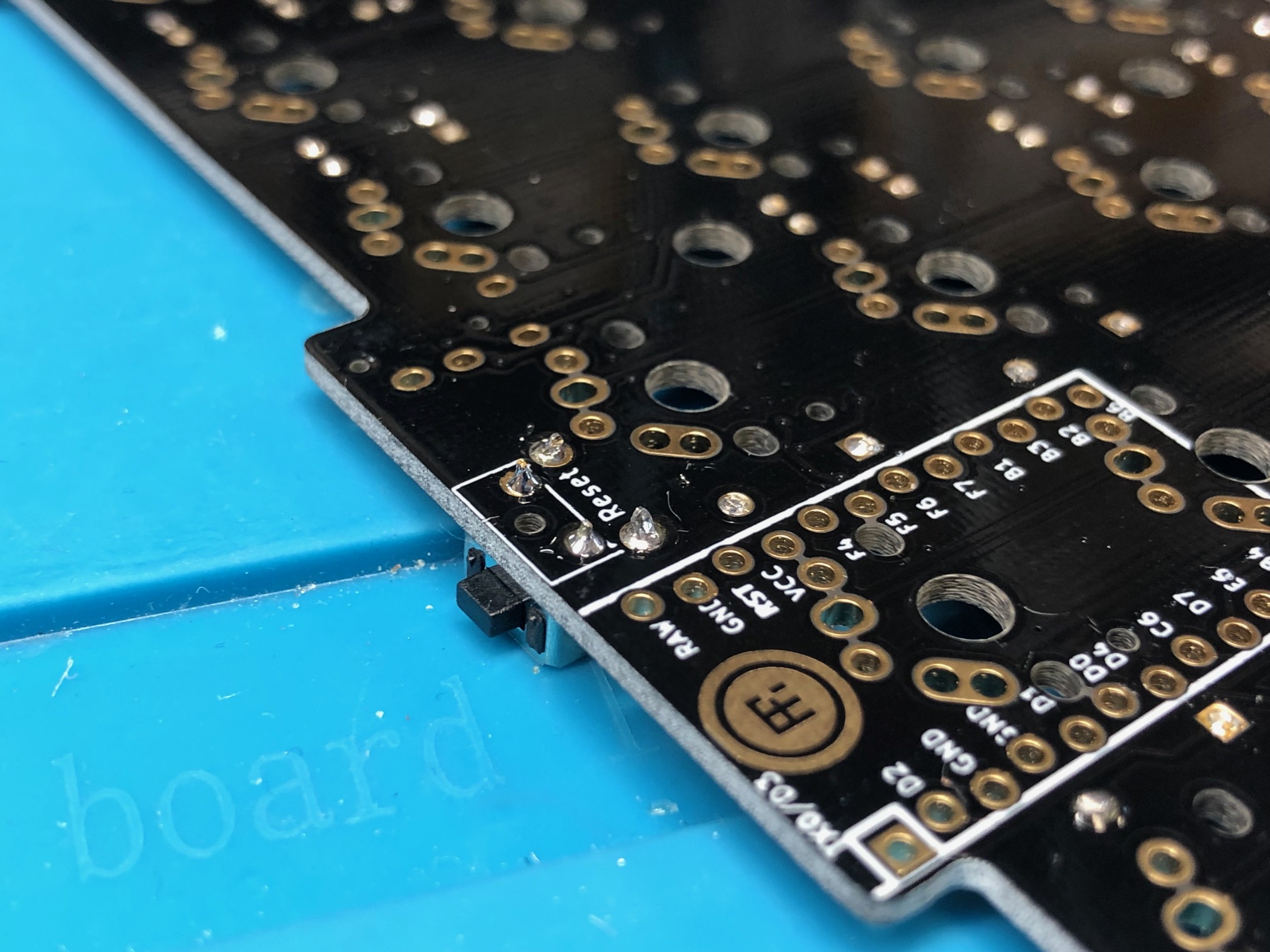
Add the reset button to the other half and repeat:
Solder the TRRS jack for the left half away from the reset switch, and solder the TRRS jack for the right half next to the reset switch:
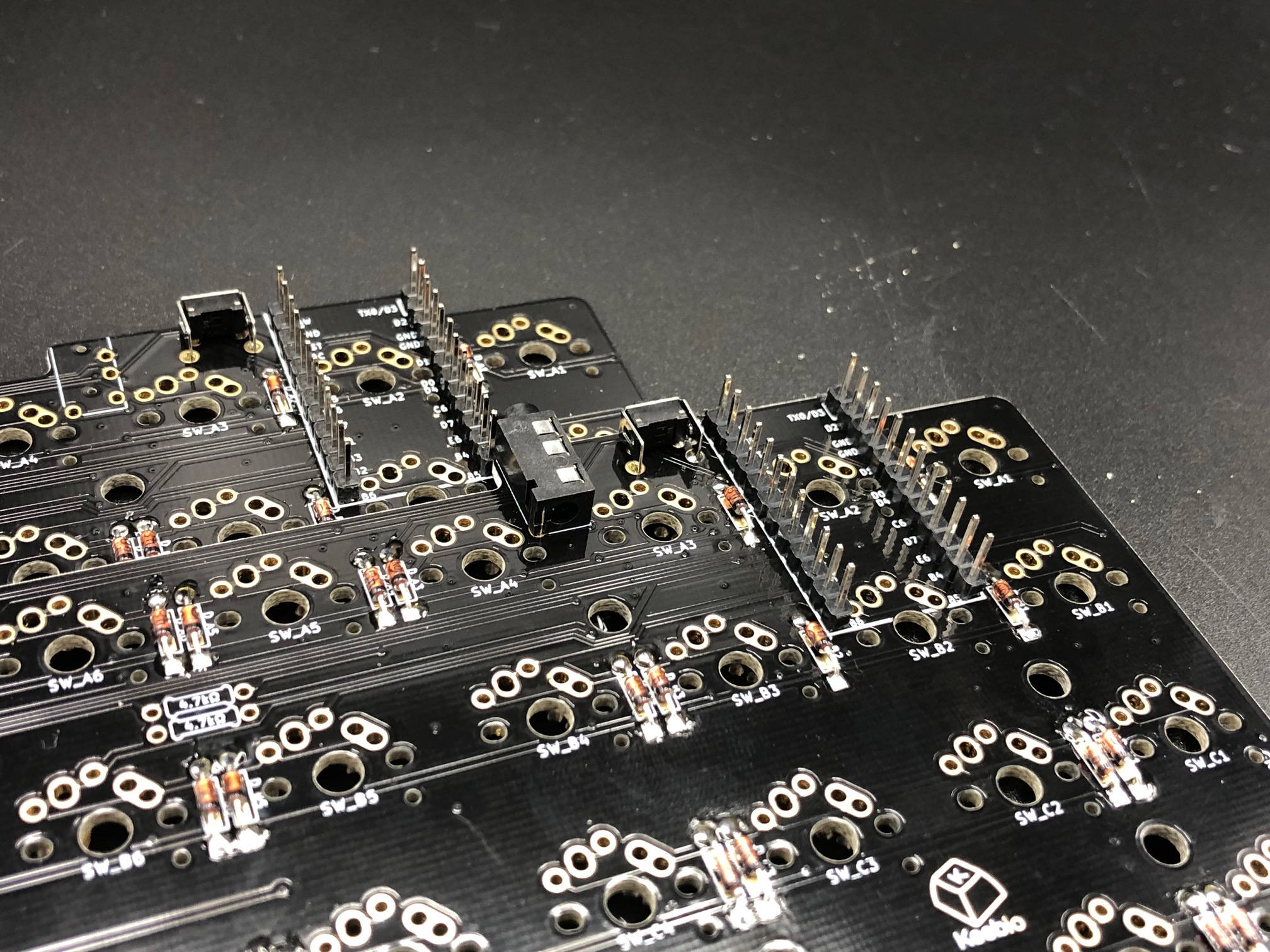
Add Pro Micro header pins
Standard installation of Pro Micro with header pins
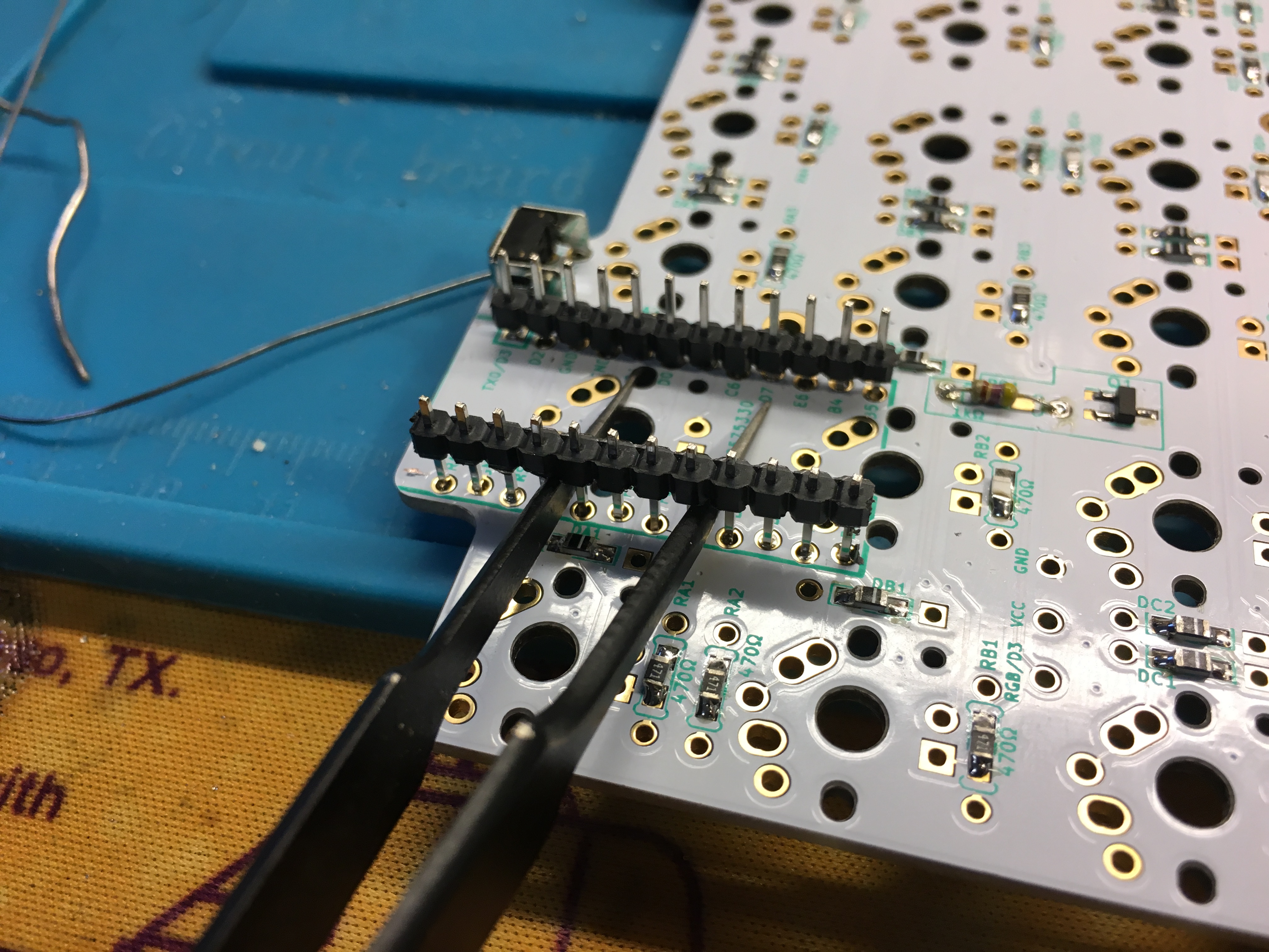
Insert the header pins into both PCBs:
Flip the PCBs over and solder:
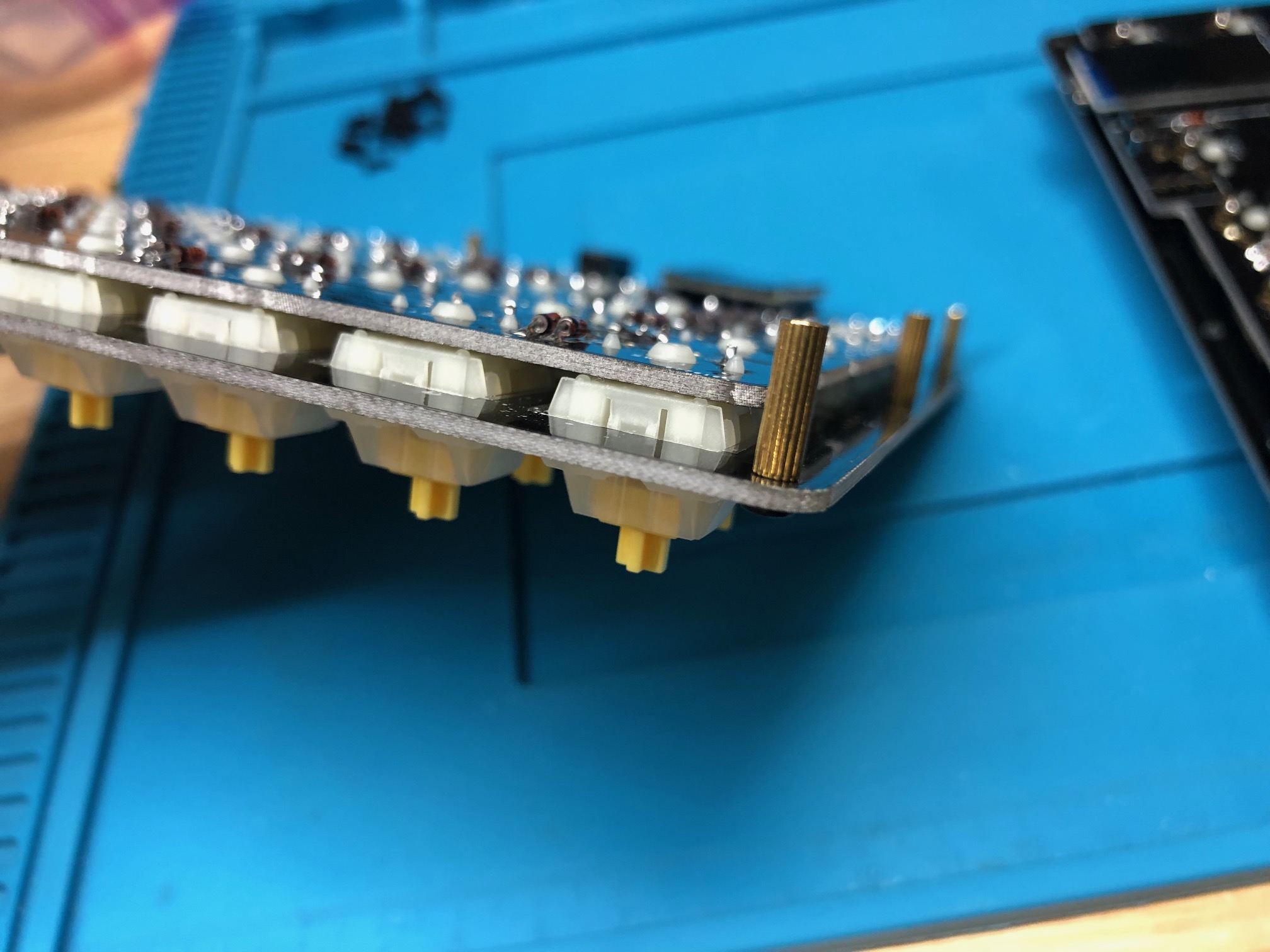
If you are doing a build with low-profile switches, you must do the following step to prevent the pins of the controller from shorting against each other. Otherwise, the switch plate will touch the header pins that are sticking out above the PCB.
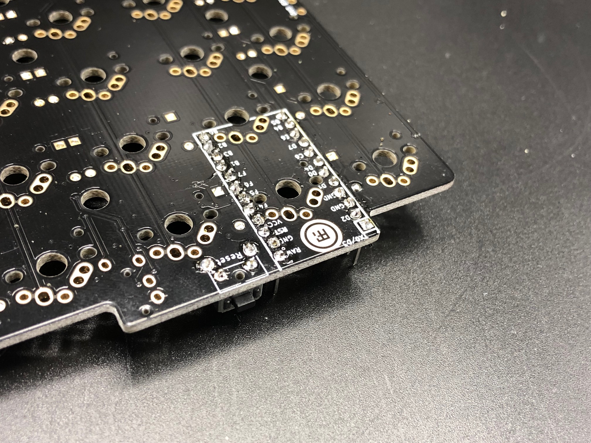
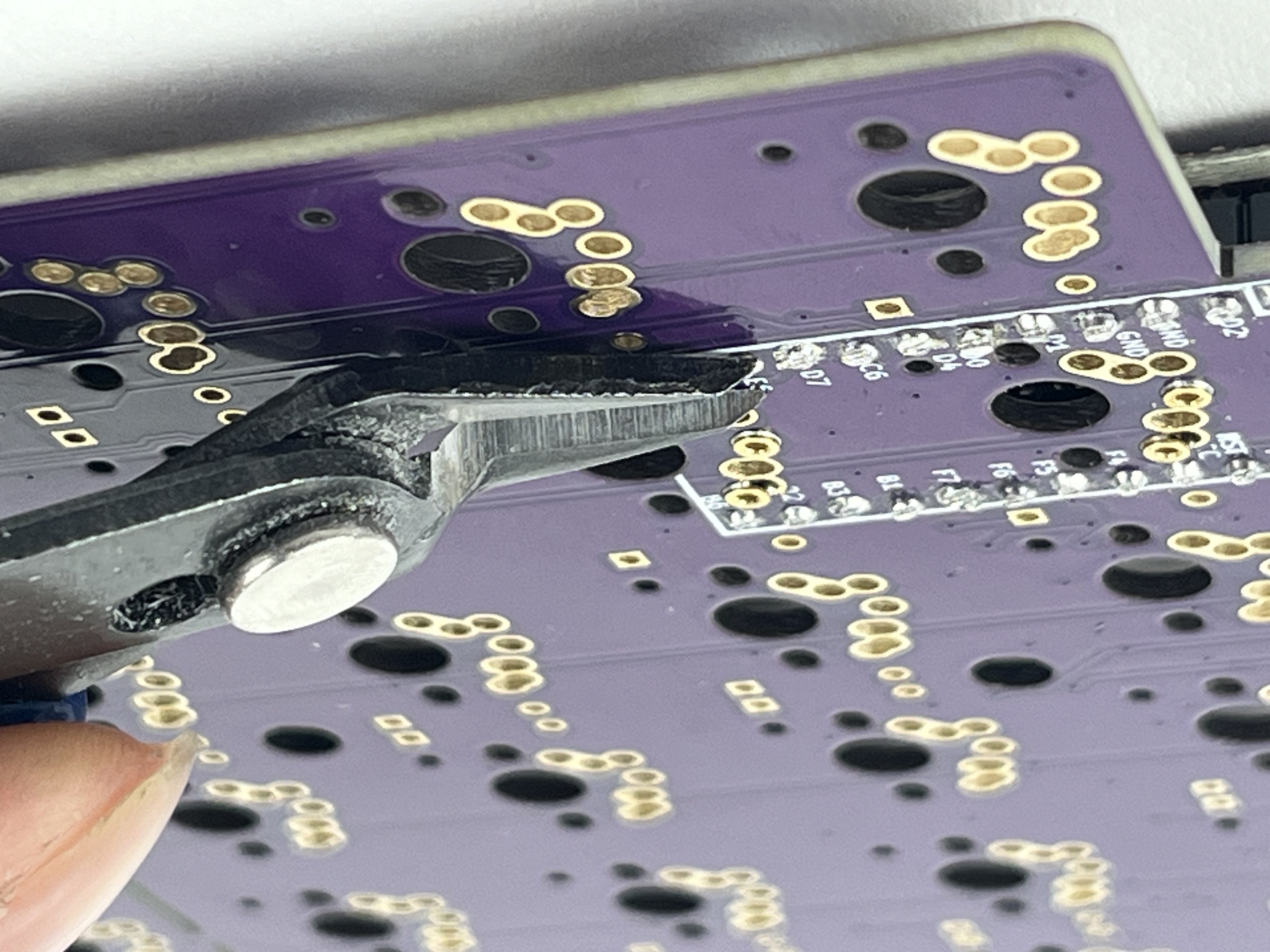
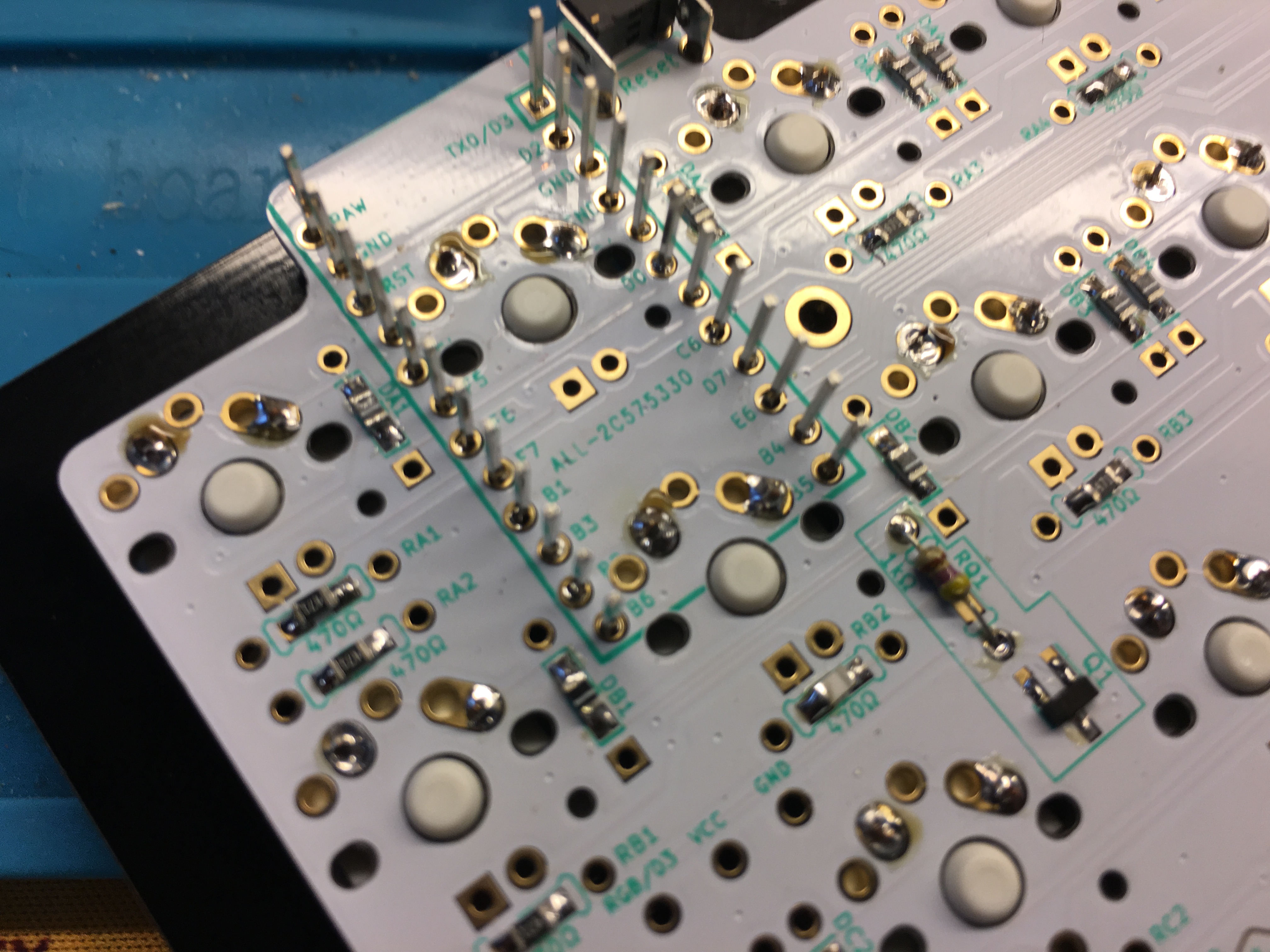
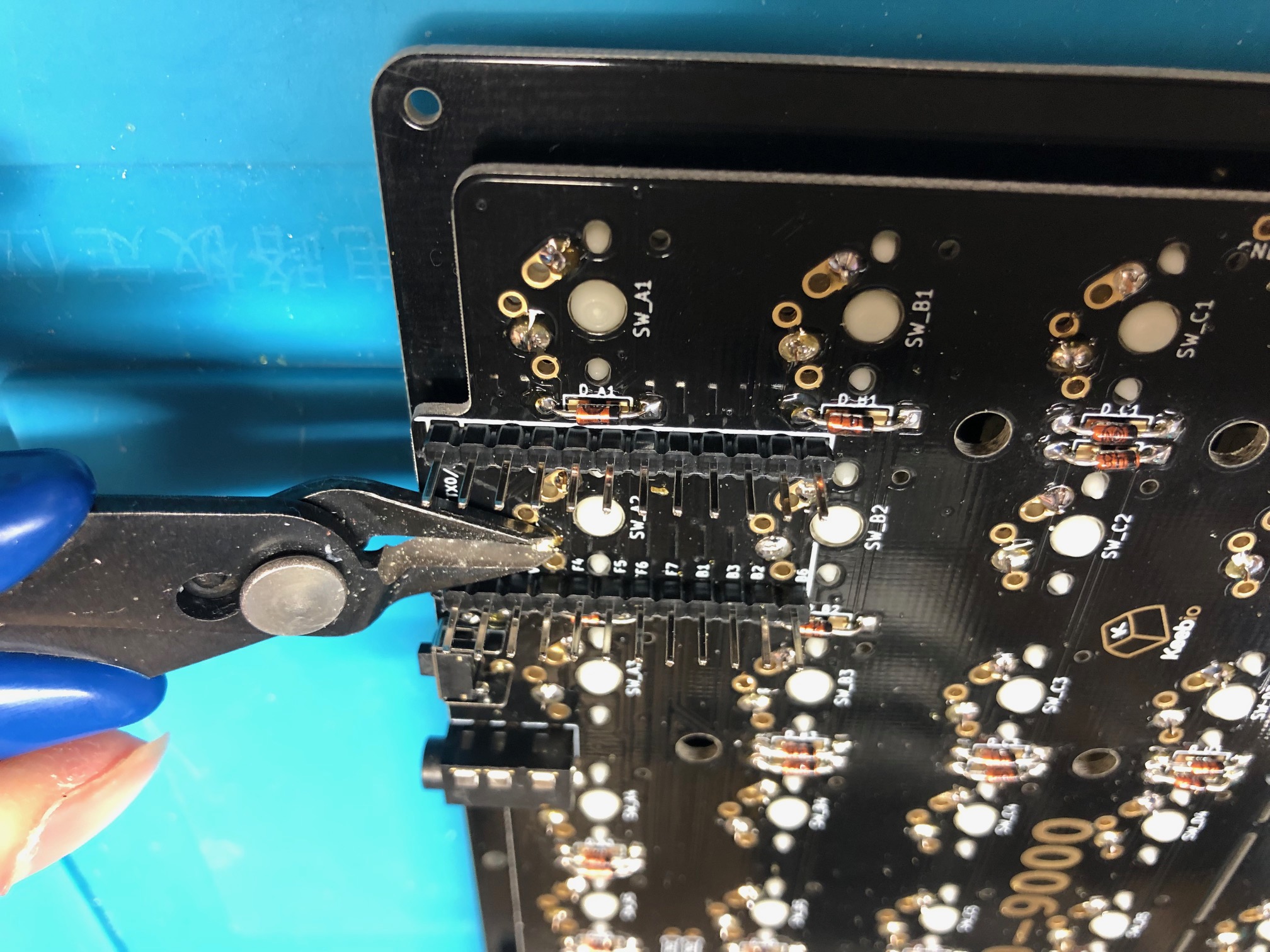
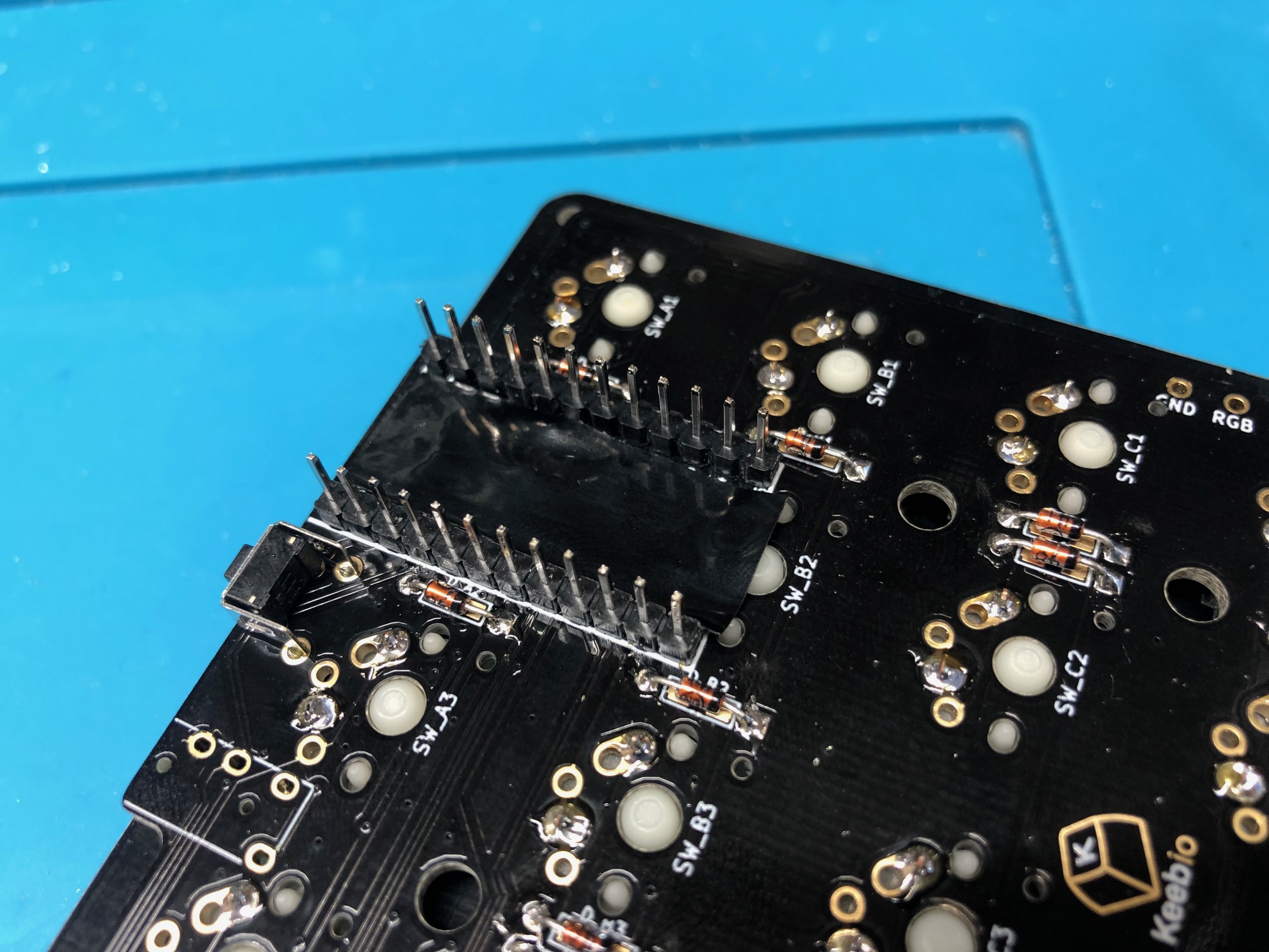
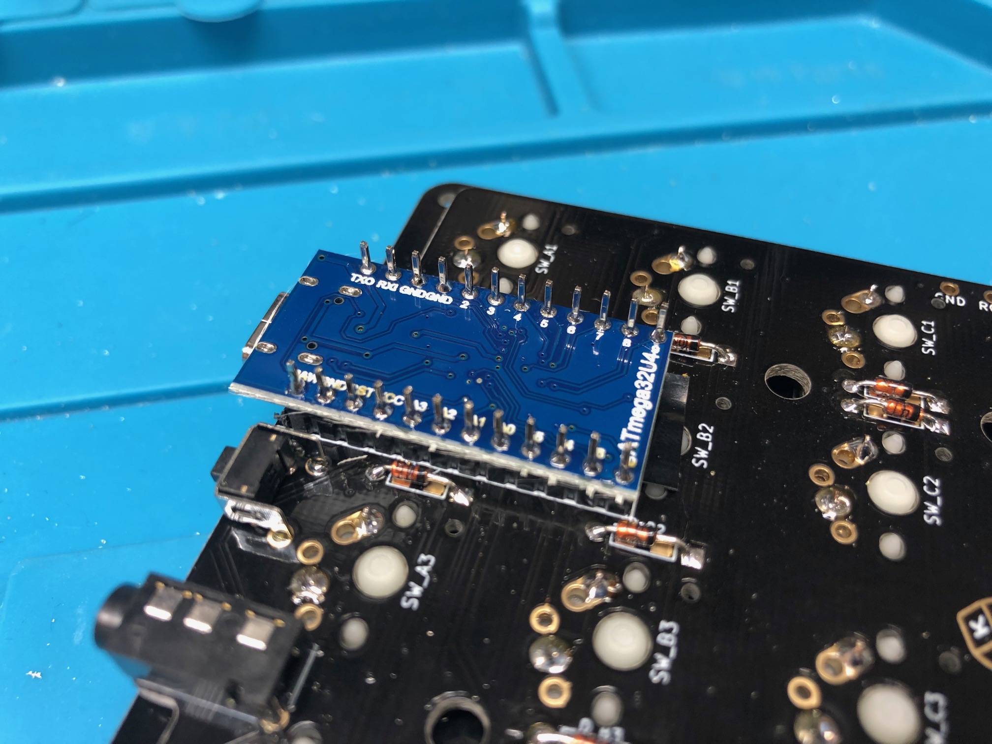
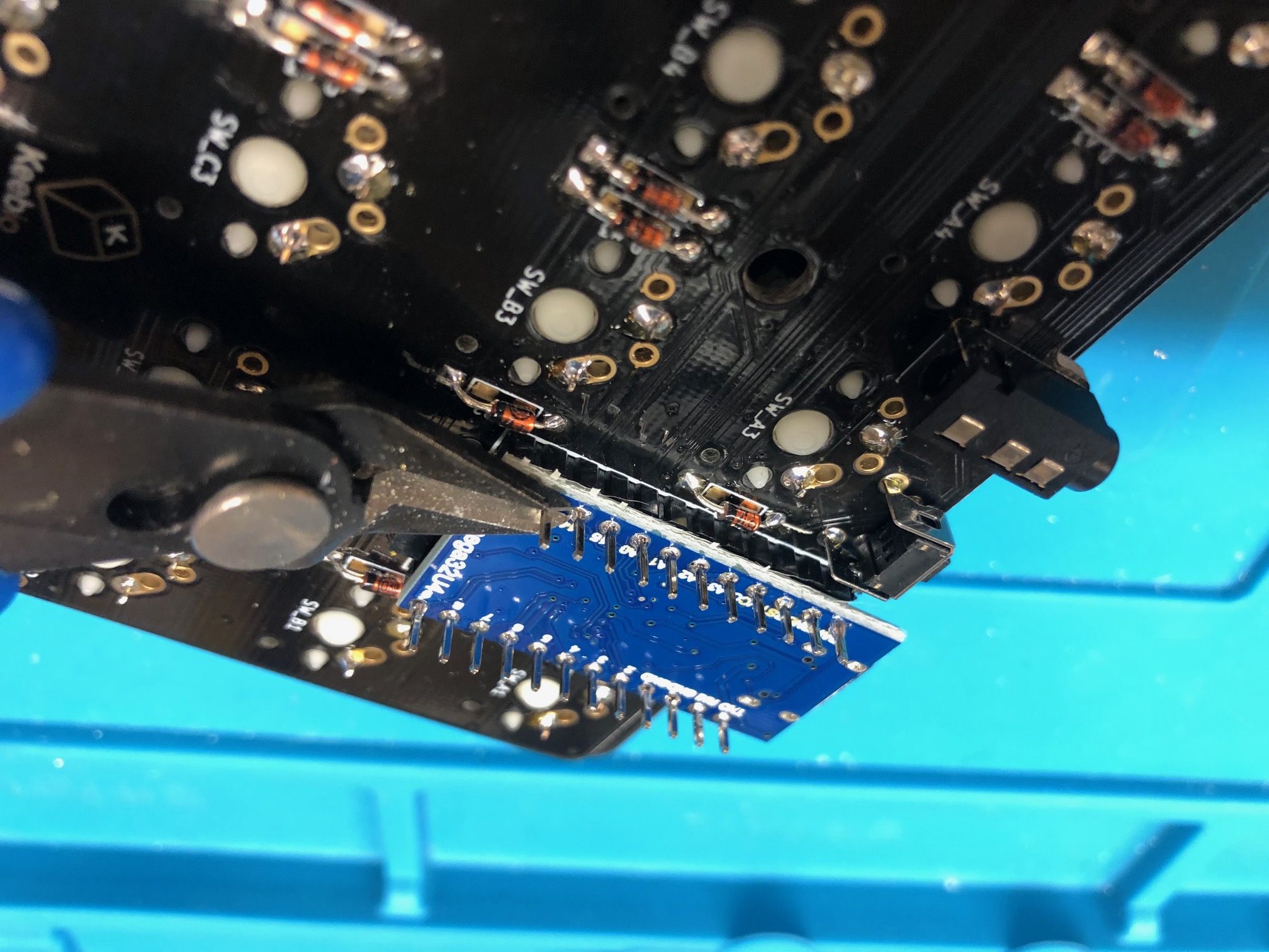
(Optional for MX, Required for Low-Profile) Trim down header pins on top-side of PCB:
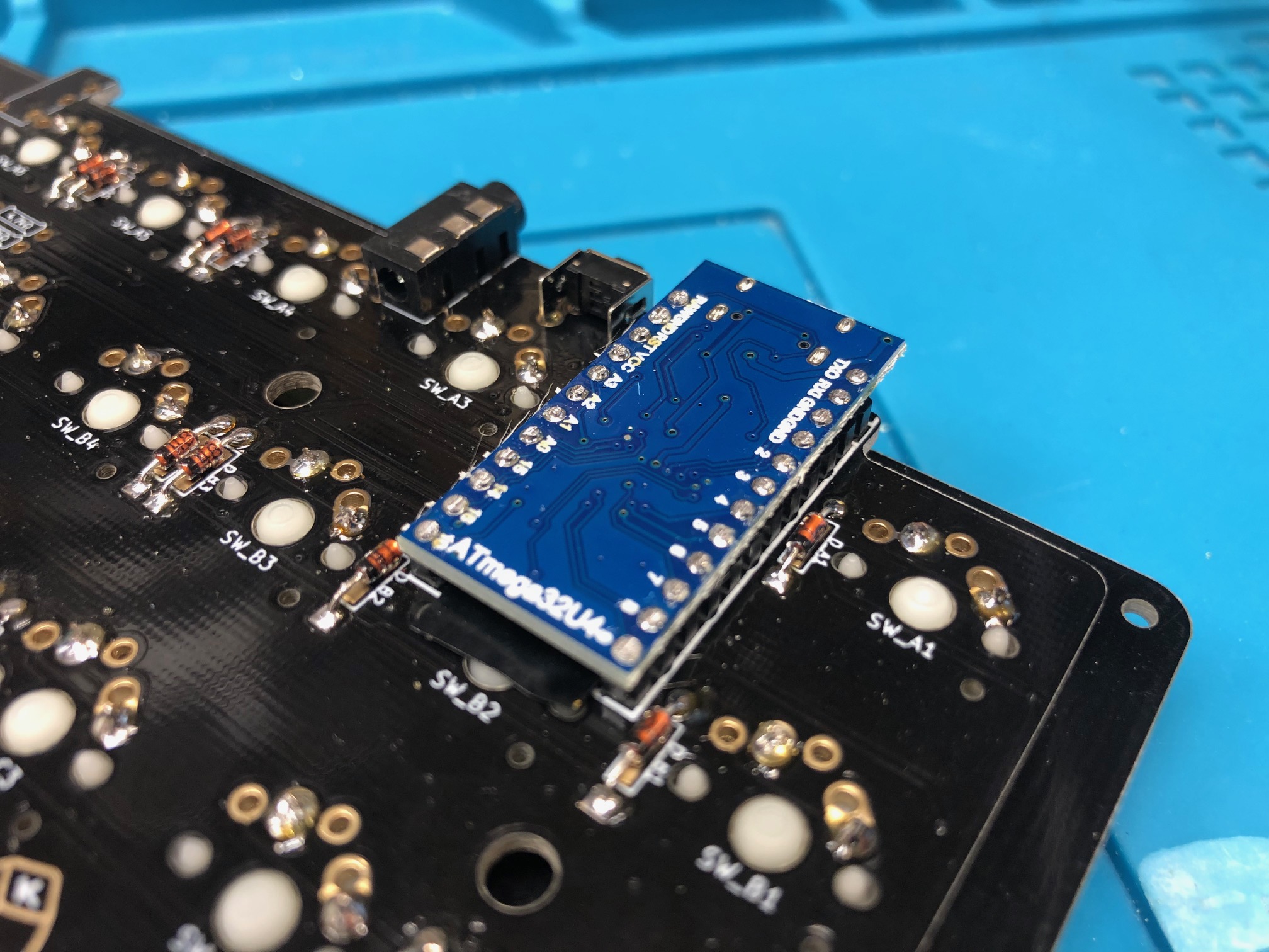
(Optional) Remove plastic on header pins so Pro Micro port is flush with PCB:
(Optional) Plastic all removed:
Don't solder on the Pro Micro yet.
Installation of Peel-A-Way sockets (optional)
Do not install Peel-A-Way sockets for low-profile builds, as the sockets will stick out too much on the top-side of the PCB and touch the switch plate, which can cause shorts
If using Peel-A-Way sockets instead, insert strips into the PCB:
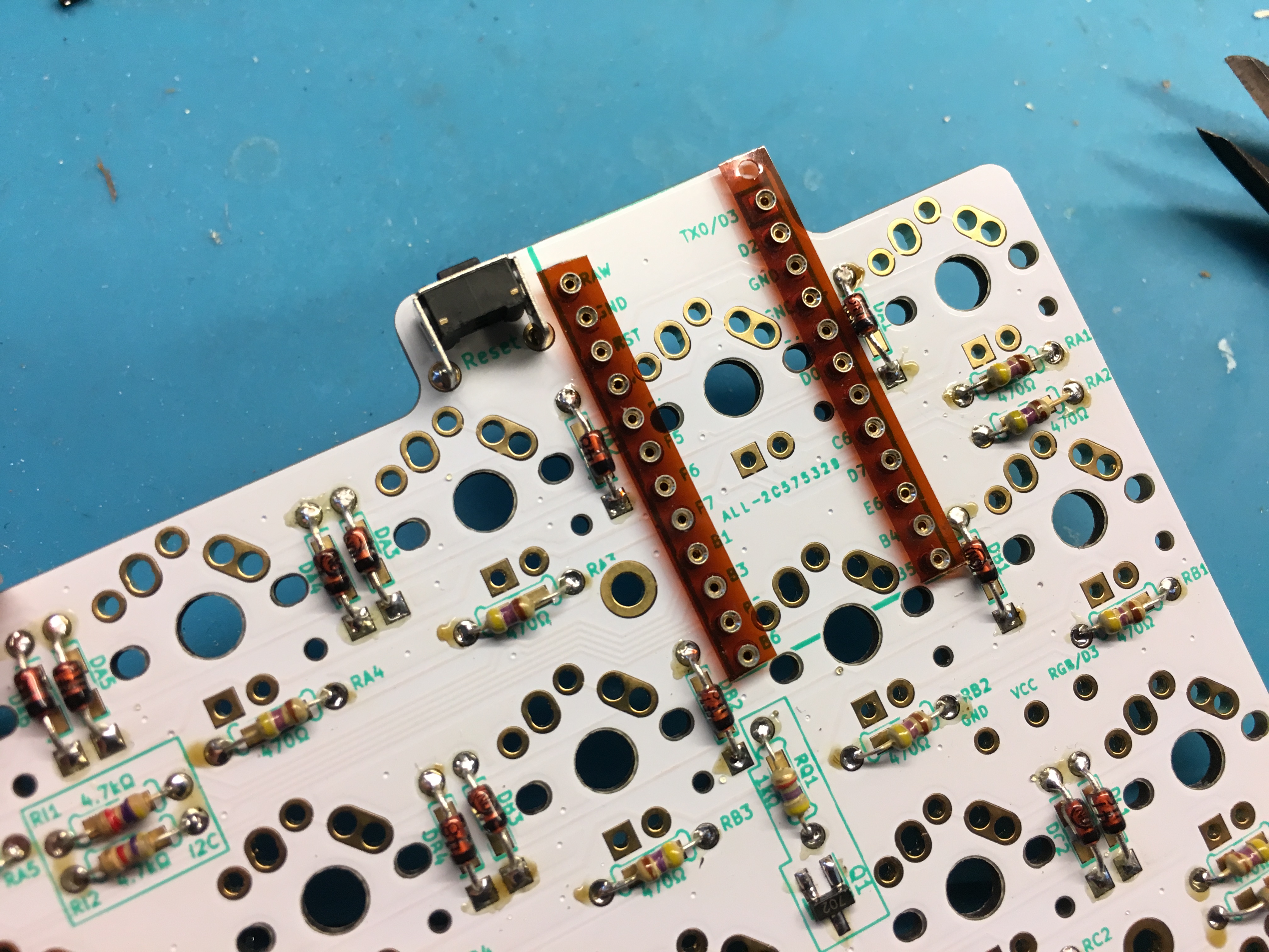
Hold the strips down using tape:
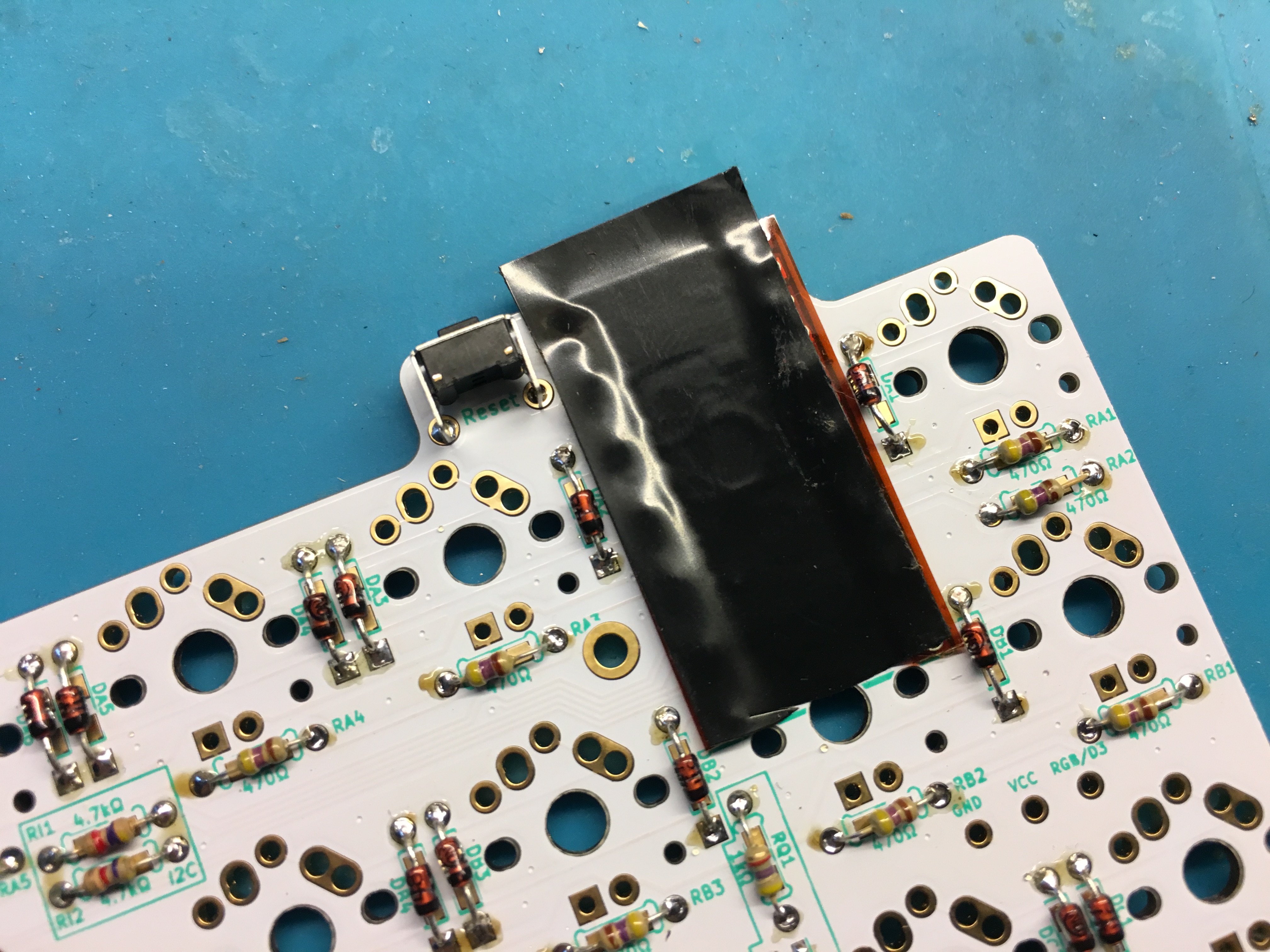
Flip the PCB over and solder the pins:
Soldering complete:
Remove plastic covering around sockets:
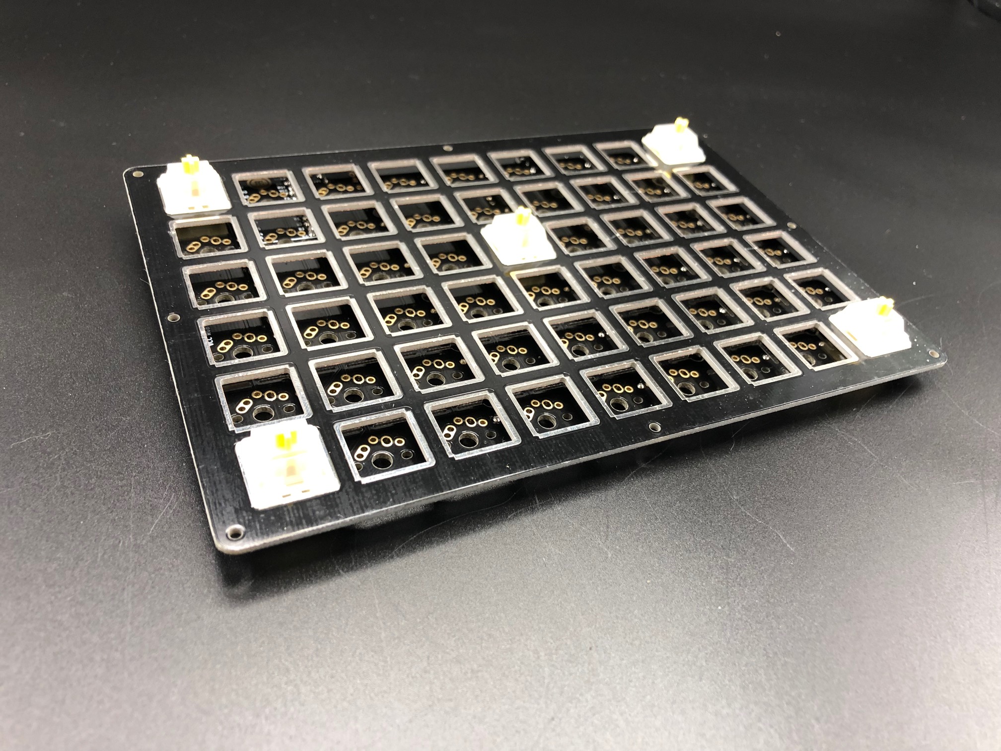
Add switches to switch plate and solder
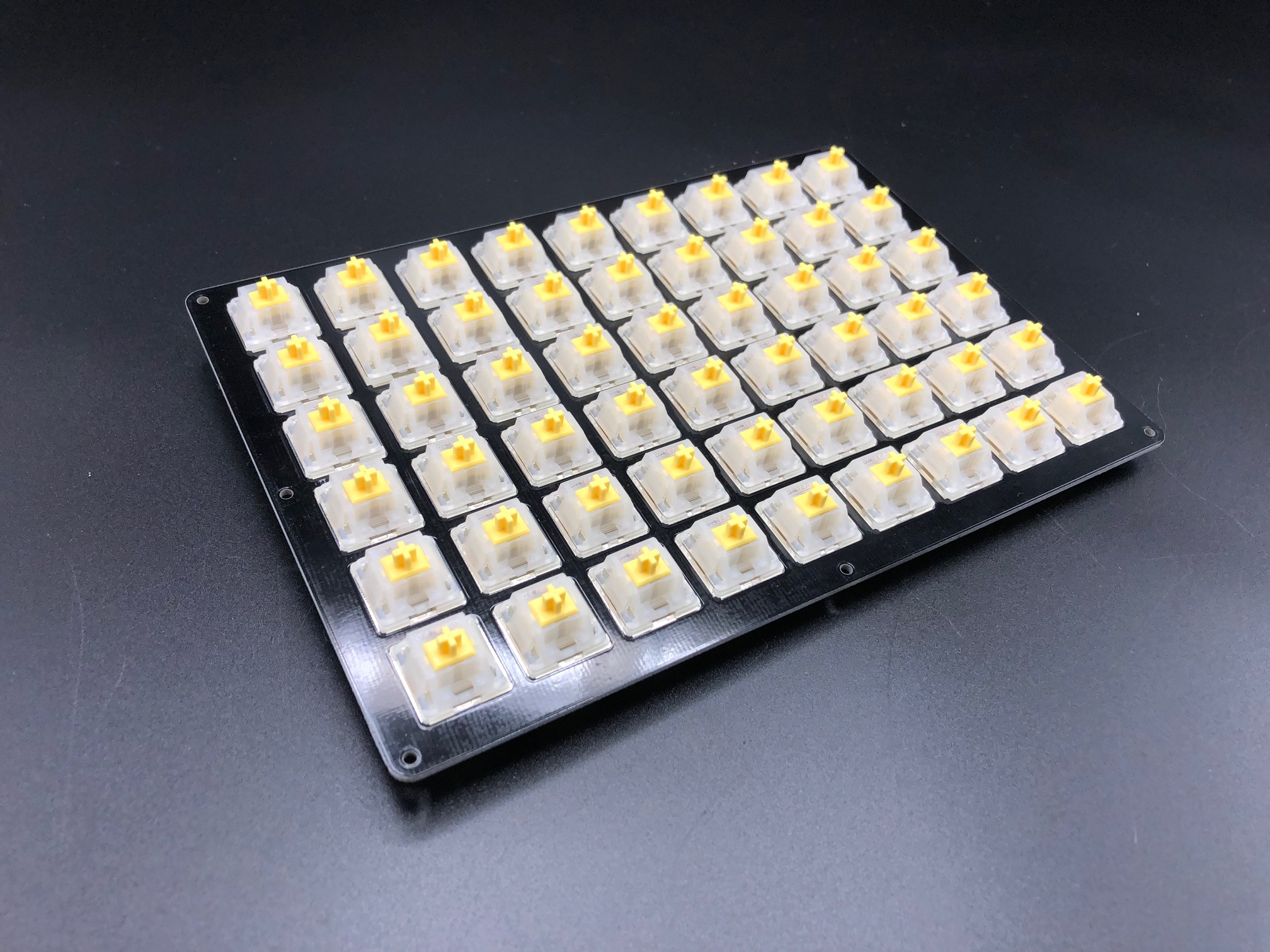
Add switches into the switch plate. It's a good idea to add switches to the corners first and then solder them before installing the rest of them:
Add the rest of the switches:
Solder the rest of the switches:
Flash Pro Micros
Flash both of the Pro Micros before soldering them to the board to ensure that they work properly.
Solder Pro Micros
Standard Installation
Clip the switch pins of the switches that will be covered up by the controller, so the pin don't come in contact with the controller:
Add a piece of electrical tape on top of the clipped pins:
Place Pro Micro onto the header pins:
Solder the header pins to the Pro Micro:
Clip the excess length of the pins:
All clean, now do the same for the other half.
Add tape on top of the Pro Micros to prevent them from touching the bottom plate:
Solder RGB strip (Optional)
See the Adding RGB Underglow Guide:
Assemble case
Insert the screws through the top of the switch plate and attach standoffs from the bottom side of the plate:
Put bottom plate on and add screws:

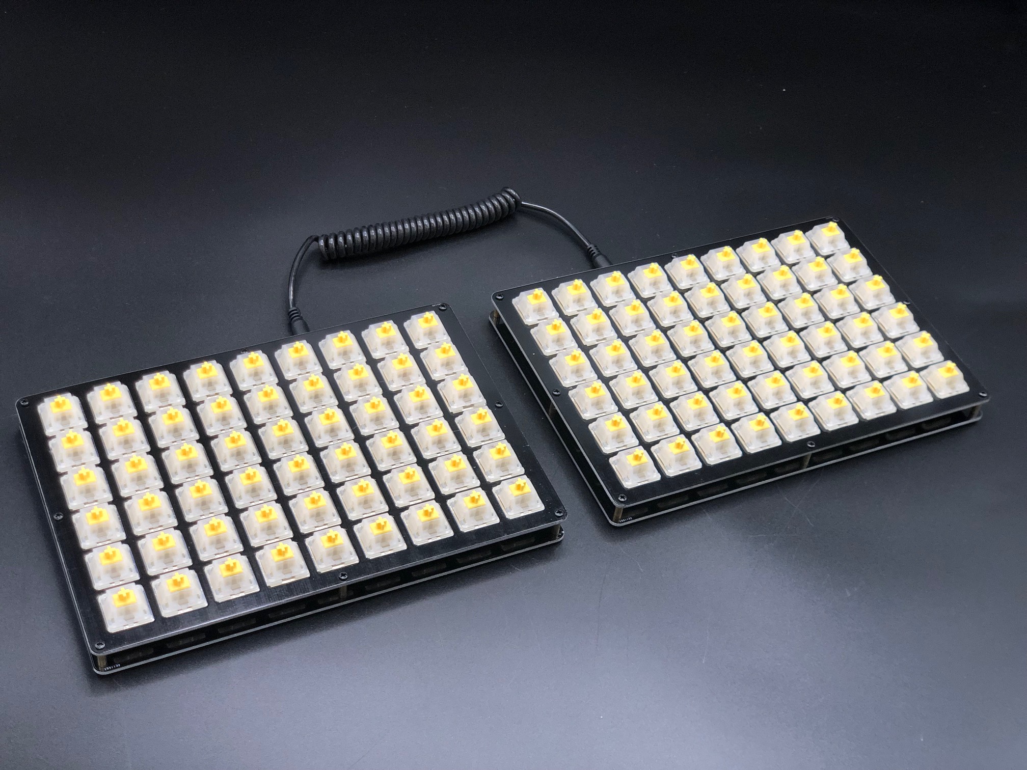
You did it!:
Firmware
Pre-compiled VIA-enabled firmware builds can be found below, choose the file corresponding to the controller you used: