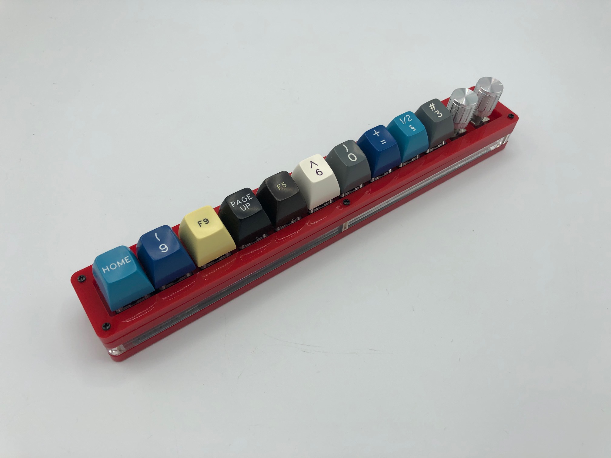
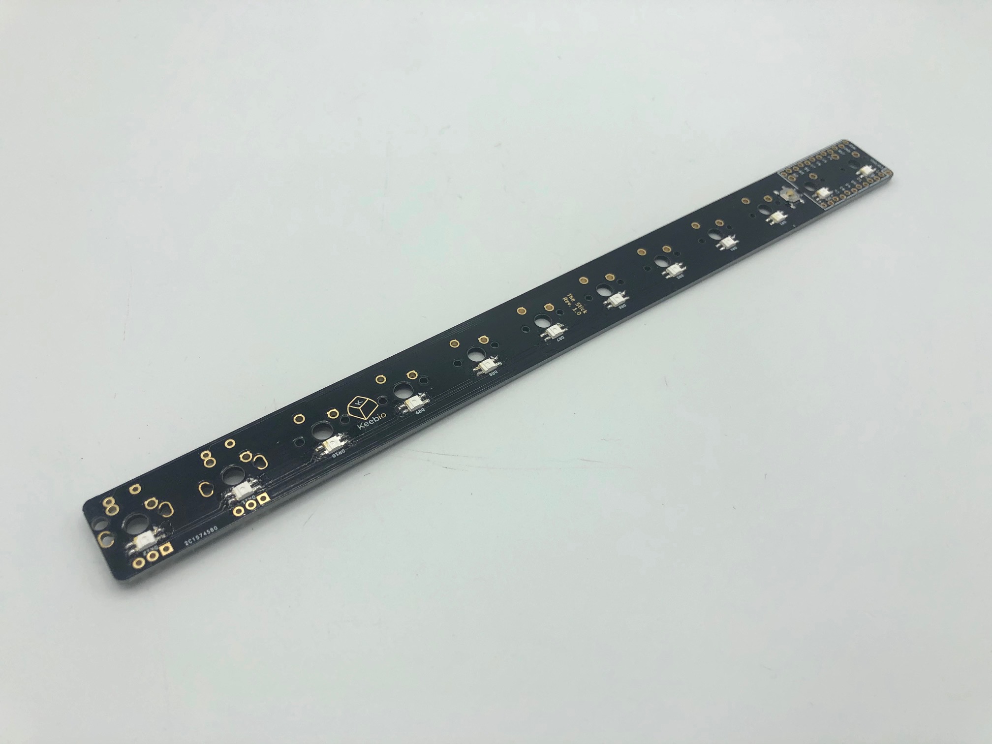
The Stick
Videos of Builds
Here's a list of build videos various people have created:
Parts List
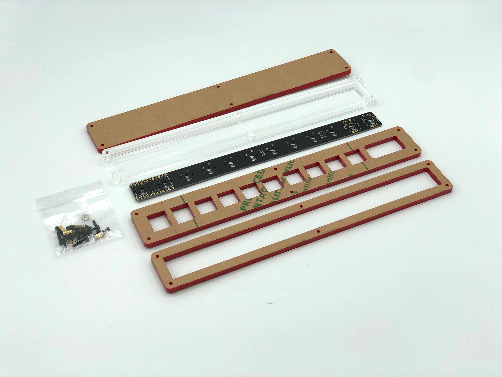
Here's a list of parts needed for the build:
- PCB & Case:
- Pro Micro-compatible Controller:
- Switches (MX-compatible only)
- Optional parts
- SK-6812 Mini-E RGB LEDs
- Rotary Encoder
- Rotary Encoder Knobs
- Flux (helps with soldering the RGB LEDs)
Build Steps
Here's a summary of the build steps:
- Program Pro Micro-compatible controller
- Peel off protective paper from acrylic
- Solder reset button
- Solder RGB LEDs (optional)
- Solder header pins
- Solder switches
- Solder rotary encoders (optional)
- Solder controller
- Assemble case
- Insert standoffs into middle layer (optional)
- Screw standoffs into switch plate
- Attach bottom plate using screws
Program Pro Micro-compatible controller
Before starting the build, you'll want to flash the firmware to your Pro Micro-compatible controller first.
Please see Flashing Firmware for more info.
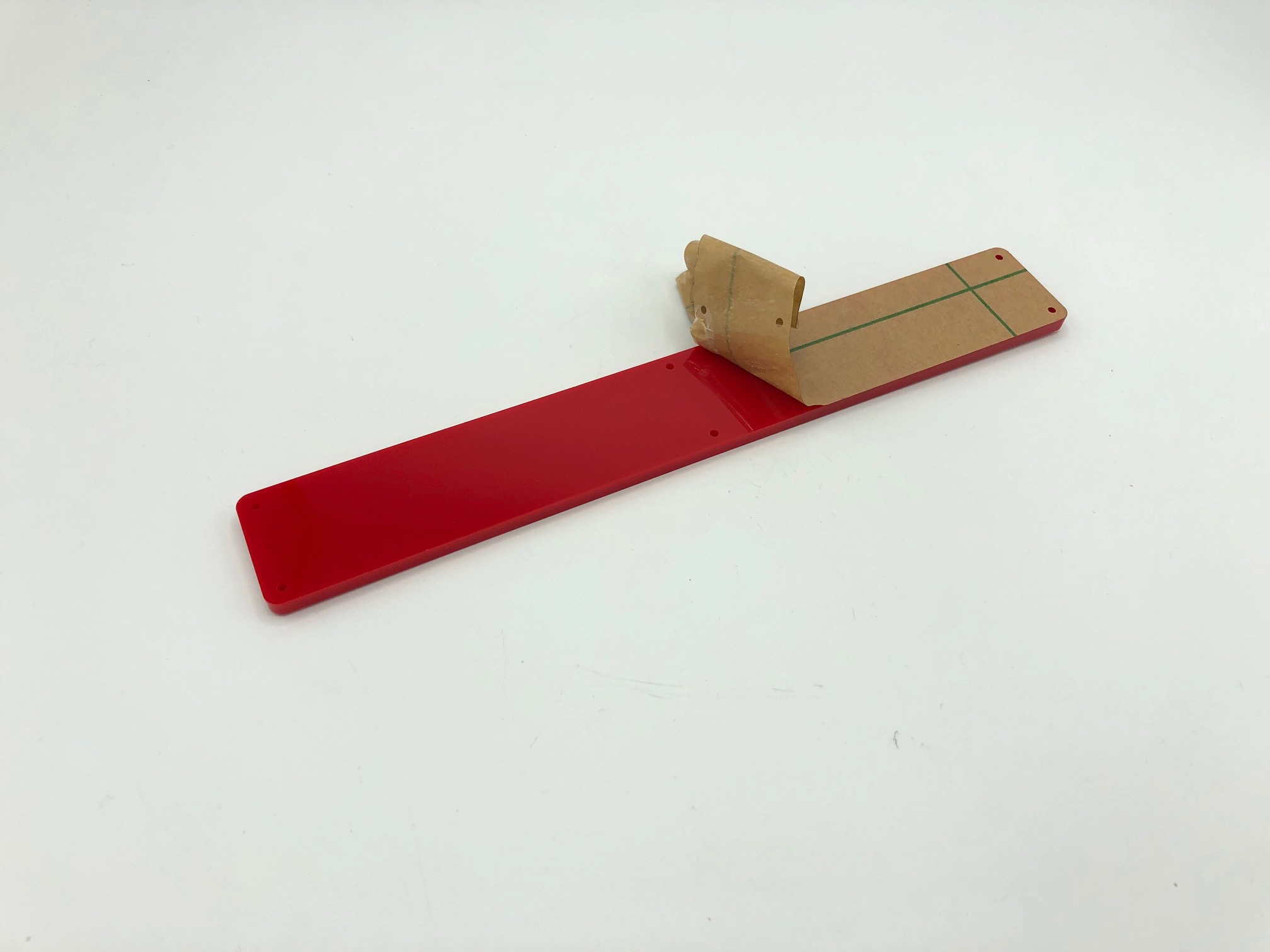
Peel off protective paper from acrylic
The acrylic pieces have protective backing paper on them. Peel off the paper before assembling everything together.
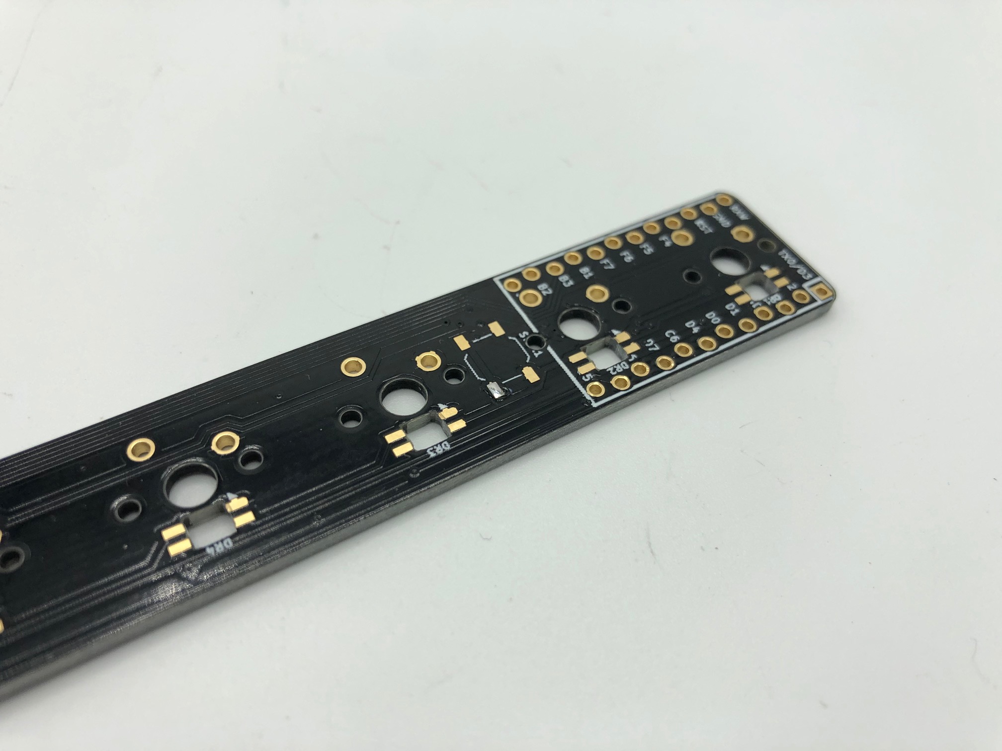
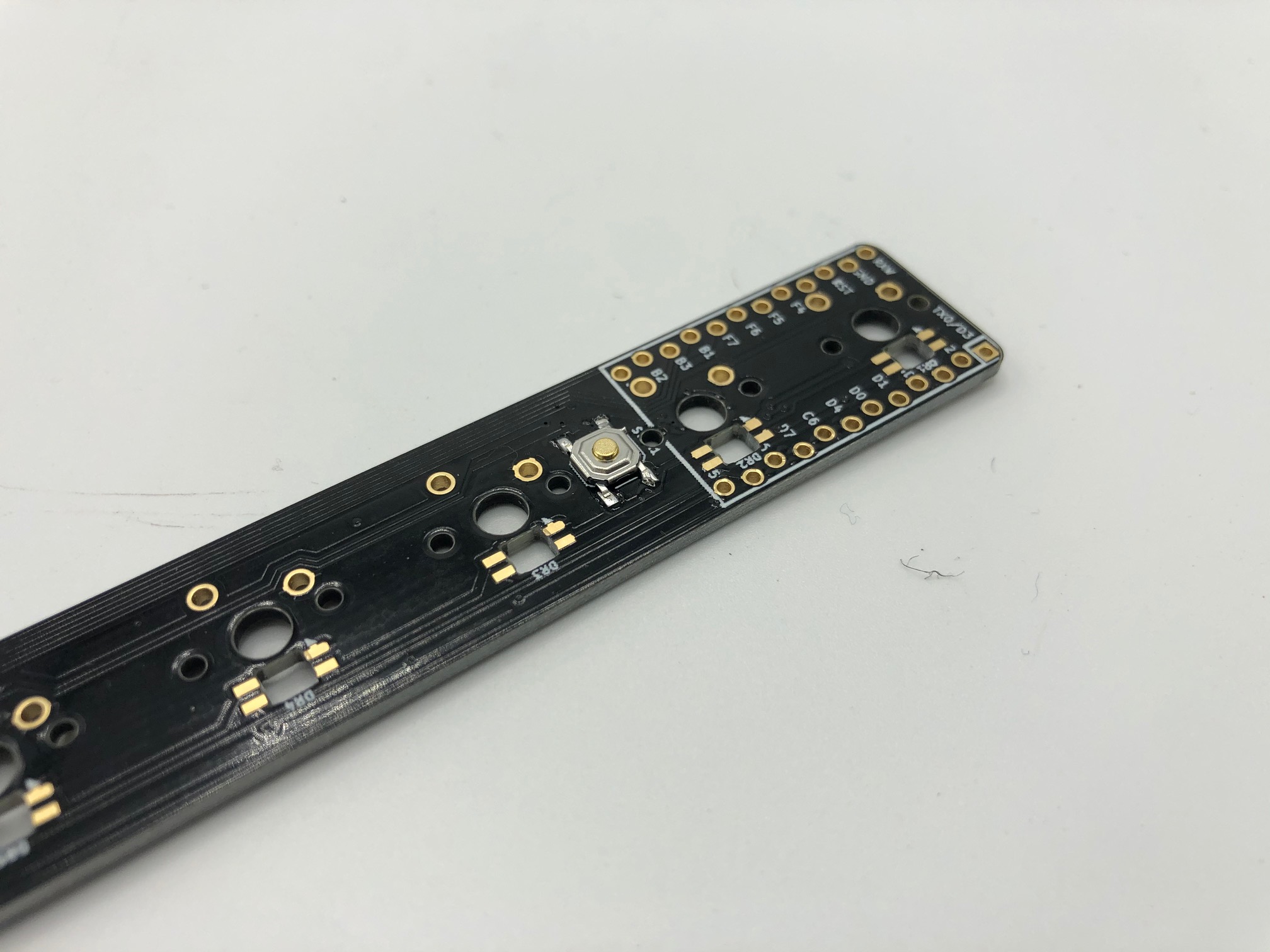
Solder reset button
First, tin one of the pads of where the reset button will go on the PCB with solder.
Next, align the reset button on the PCB and heat up the pad you added solder to. Reheat and align as necessary.
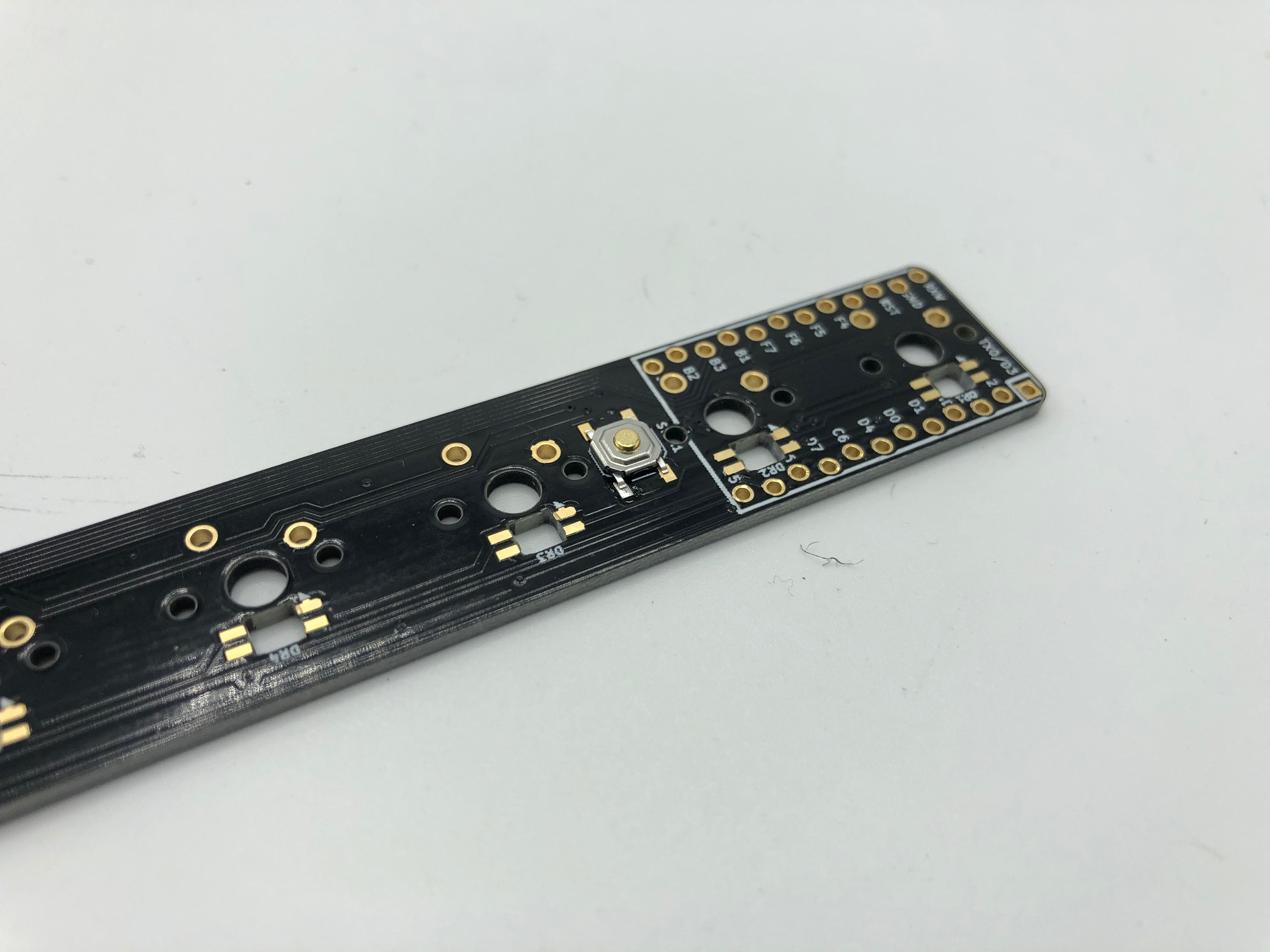
Once you are satisfied with soldering the first pin, solder the other three pins.
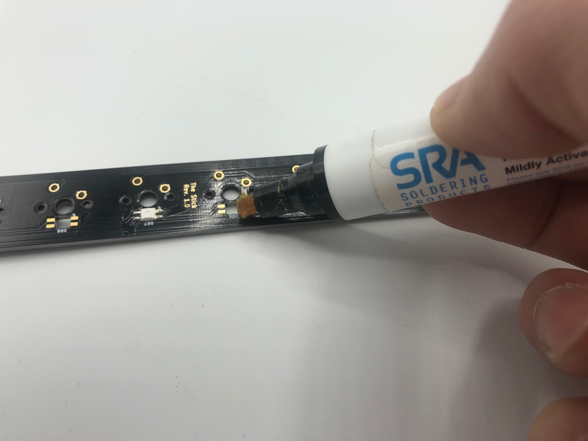
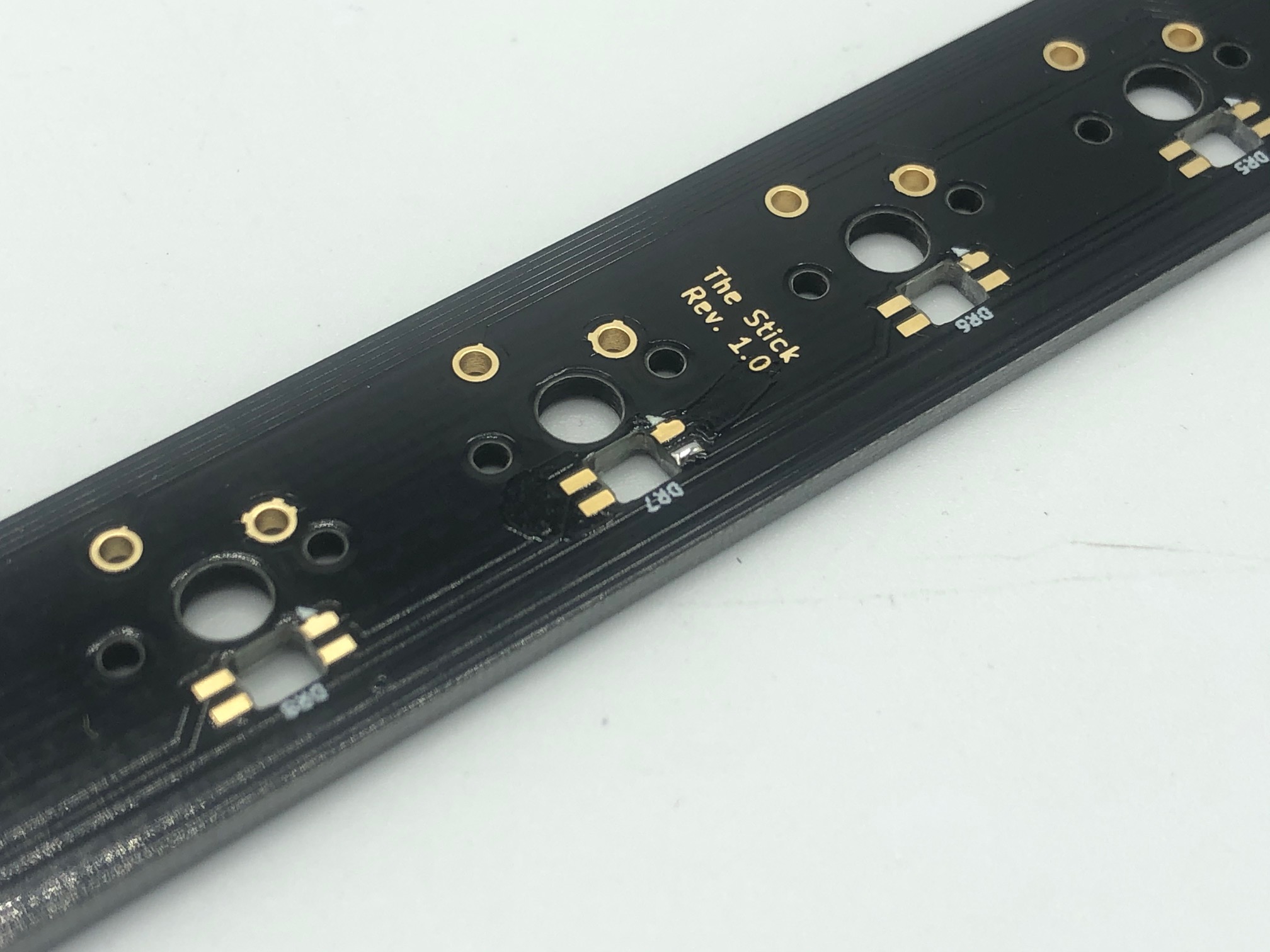
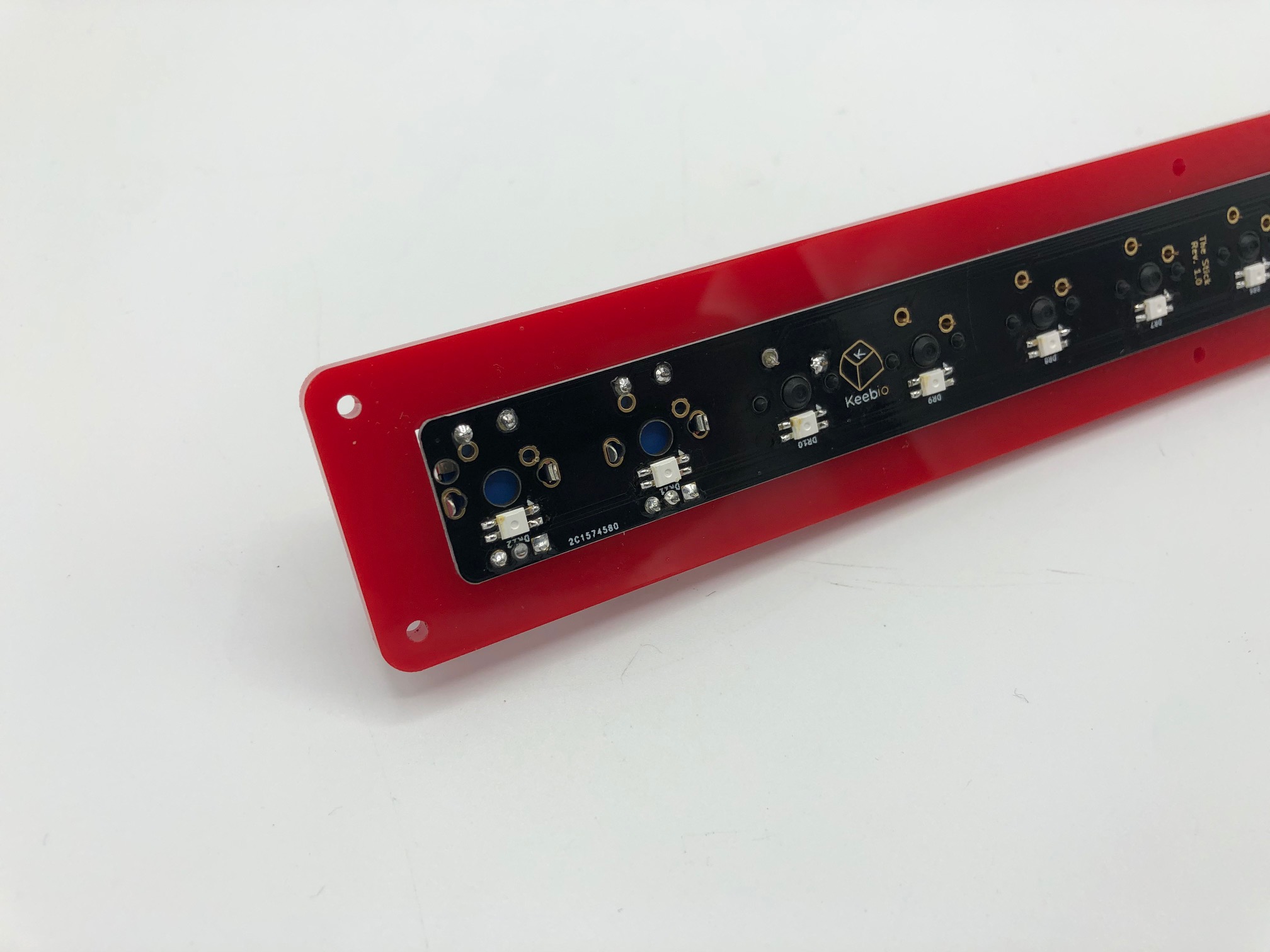
Solder RGB LEDs (optional)
If you have flux available, it's recommended that you add some to each pad of the RGB LED spots.
Tin one of the pads of the RGB LED slot. Don't pick the one with the white triangle above it, since that is the GND pad which requires a bit more heat to solder, so you'll have an easier time if to select one of the other three pins to do first.
Place the RGB LED into the slot. Make sure the leg on the LED that has an angled notch on it matches up with the pad on the PCB with the white triangle above it. Then solder the leg.
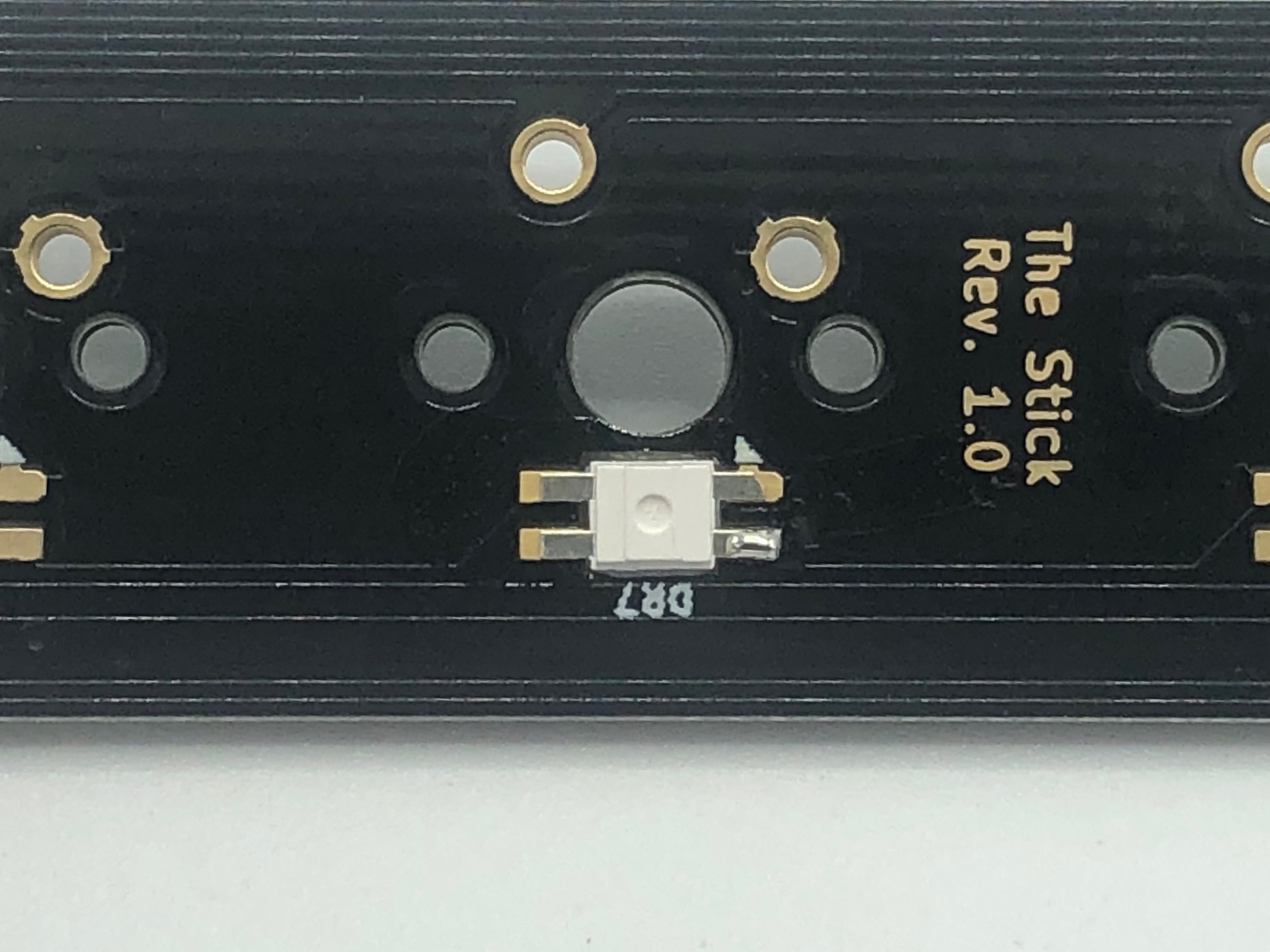
Once you're happy with the first leg of the LED, solder the other three legs. The pad next to the white triangle may need a bit more time for the solder to flow to it than the others.
Repeat the process for all of the other LED slots.
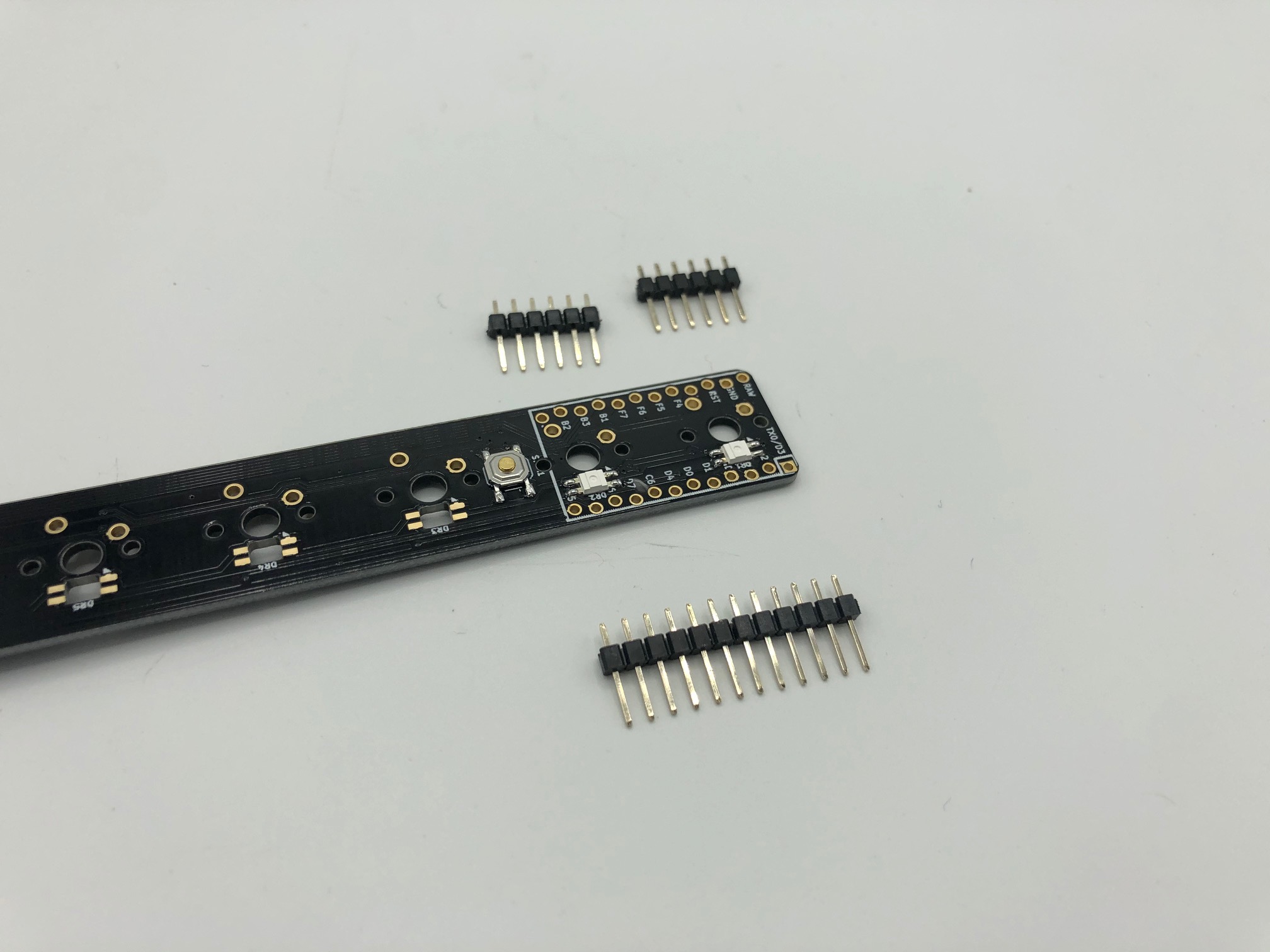
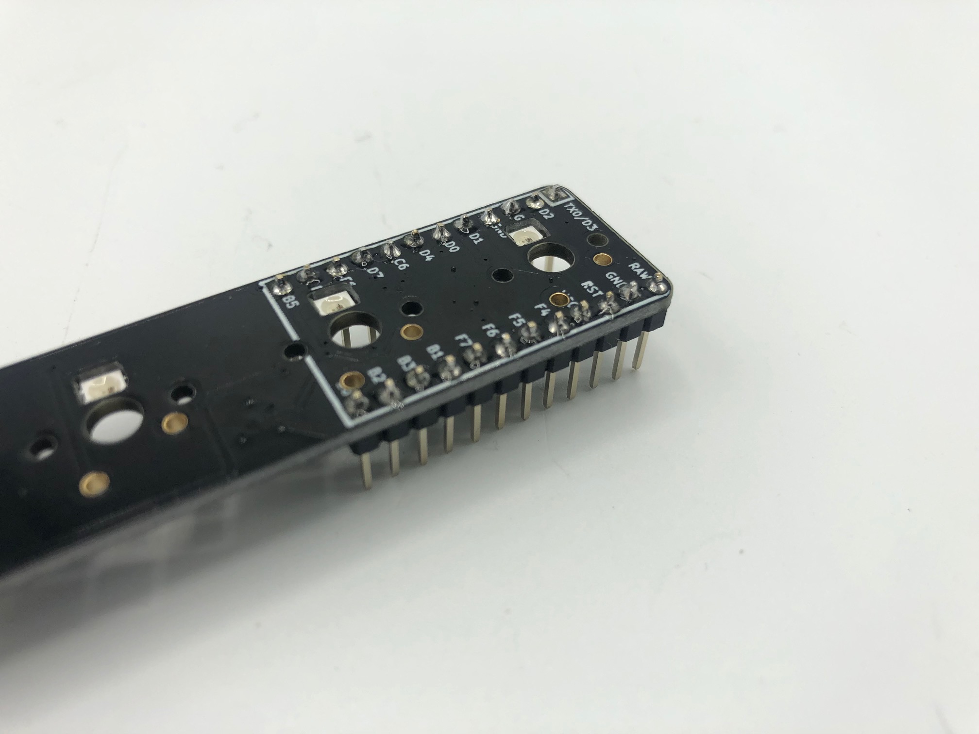
Solder header pins
There's two ways to add the header pins to the PCB. One is the traditional way of having the plastic of the header pins up against the PCB. The other way is to insert them in upside down, solder them in, and then remove the plastic.
Both methods will be covered, but it's recommended that you use the method where the plastic is removed, as you'll have a better time with soldering the switches on later near that area.
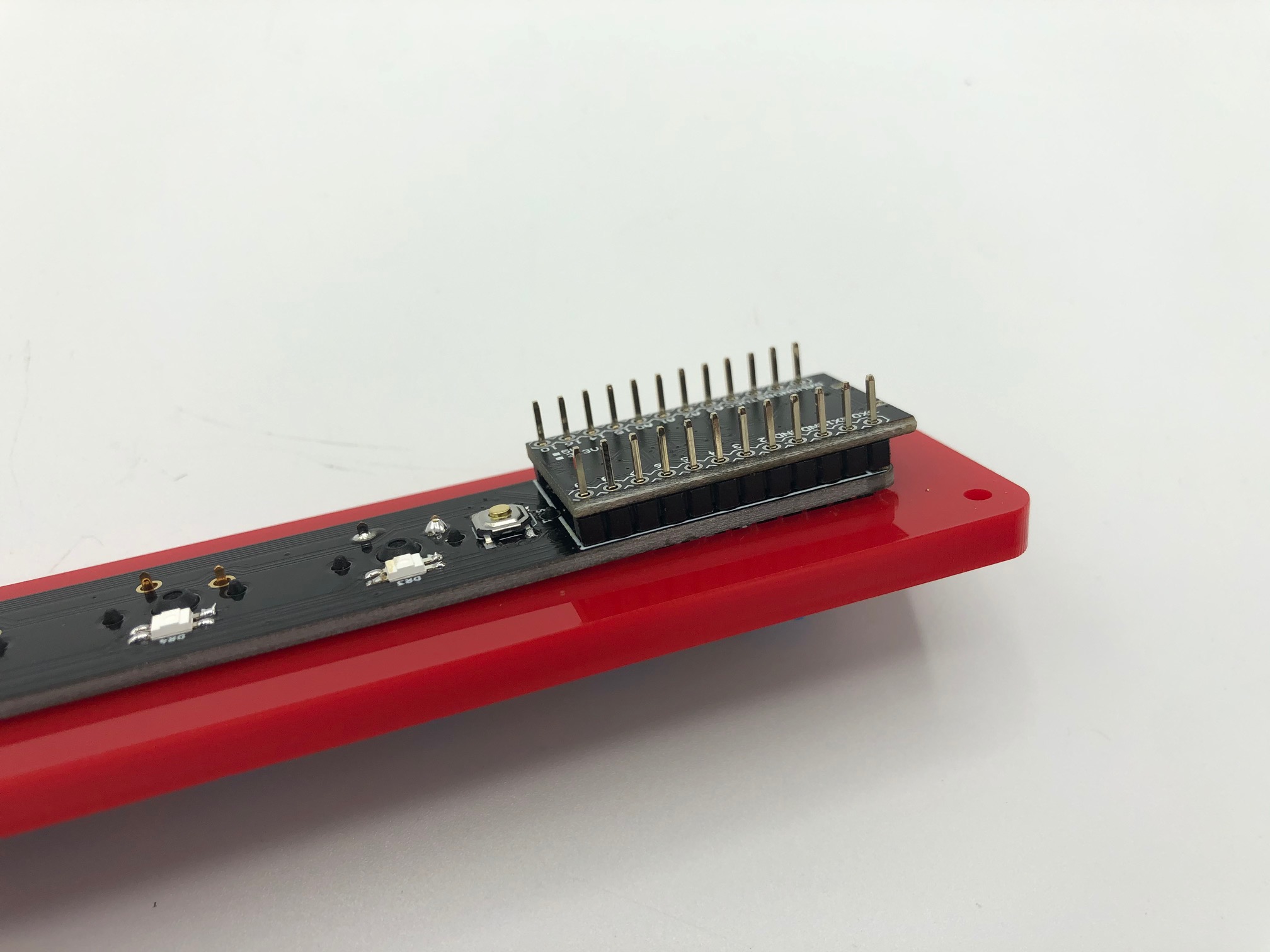
Method 1: Install upside-down and remove plastic (Recommended)
The first thing you'll need to do is take a 12-pin header and break it into two pieces of 6-pins. Doing this will make it easier for you to remove the plastic later on.
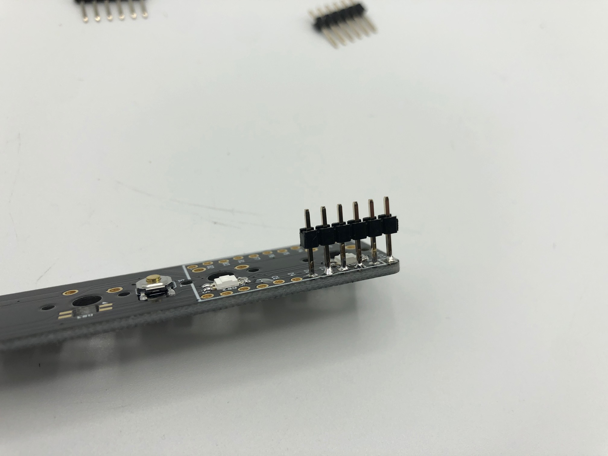
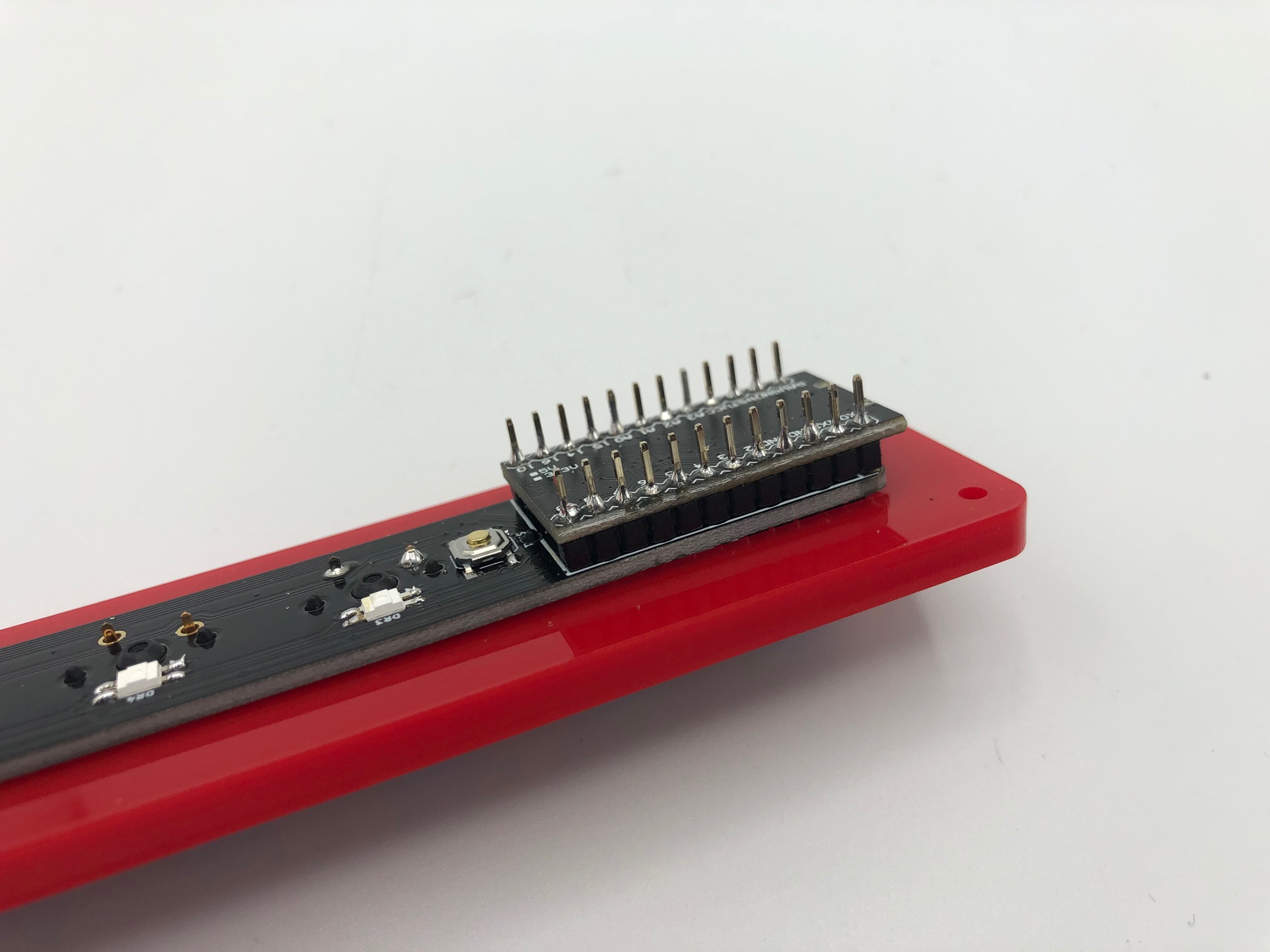
Insert the 6-pin header upside-down in the Pro Micro slot on the PCB. Make sure the PCB is flat on the table. The pins should be able to stand up on their own when inserted.
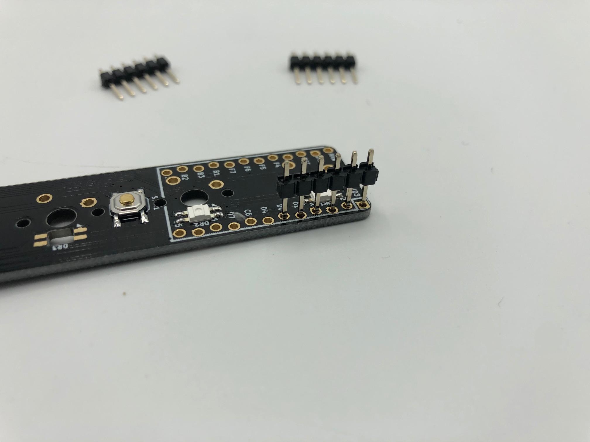
Keep the orientation of the PCB as is (i.e. don't flip the board to solder), solder the pins, and ensure each pad has enough solder on them.
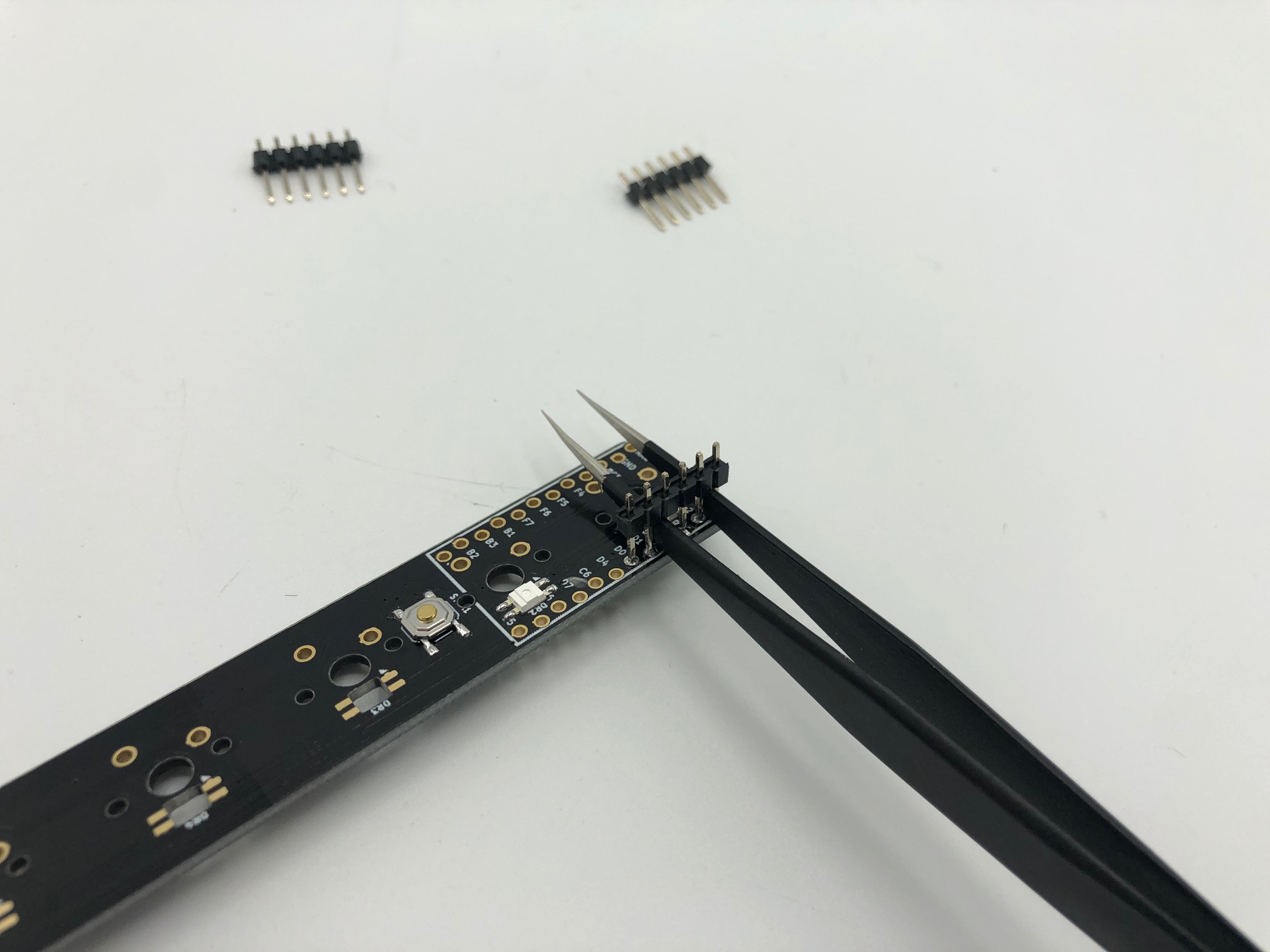
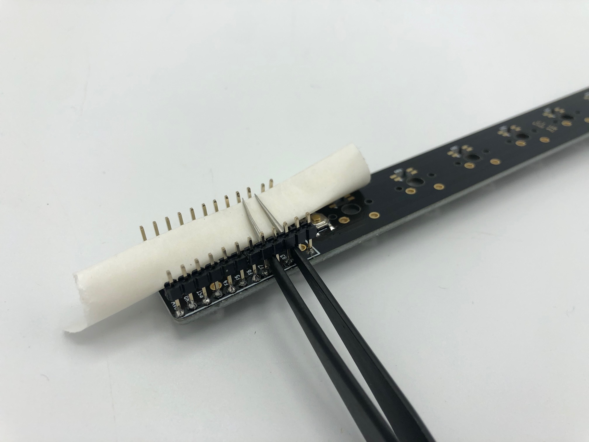
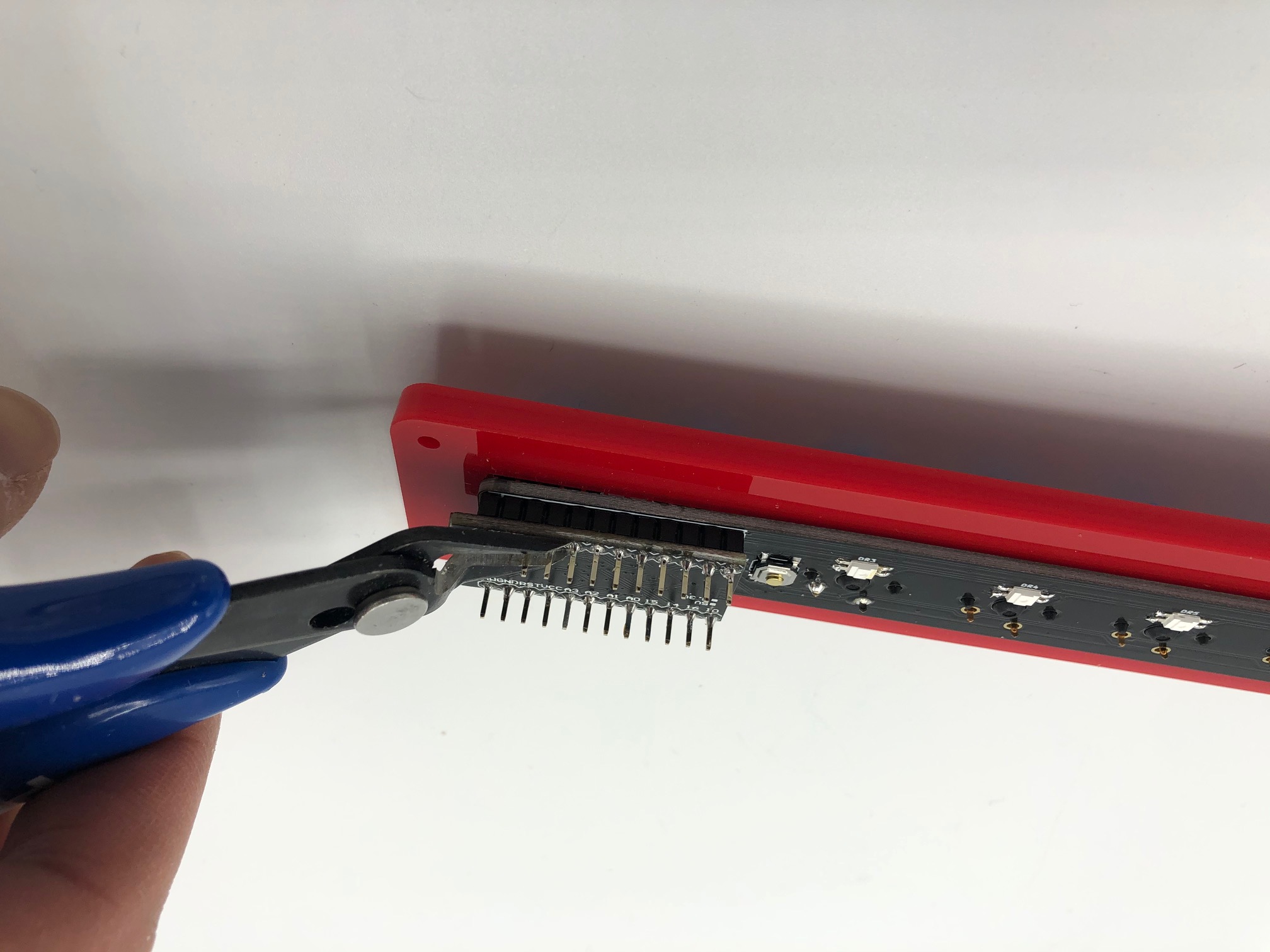
Remove the plastic from the header pins. You can usually pull them off with the hands, but you can also use a pair of tweezers to wedge the plastic off.
You may want to insert a rolled up piece of paper in between the PCB and the tweezers to protect the PCB.
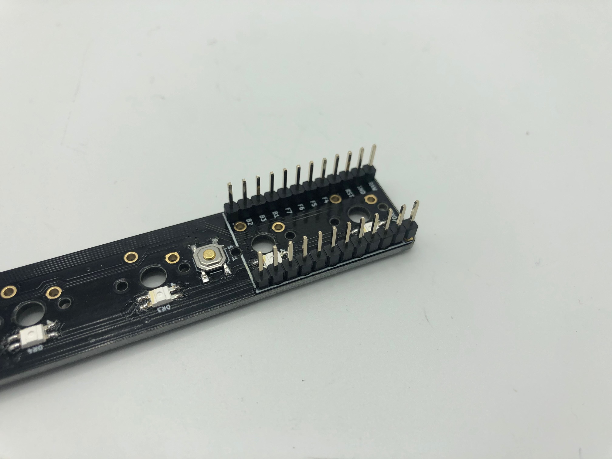
Here, the removal has been completed. Repeat the same steps above for the other three pieces of 6-pin headers.
Method 2: Traditional method
Insert the pair of 12-pin headers into the PCB.
Flip the PCB and solder the pins.
Add switches to switch plate and solder
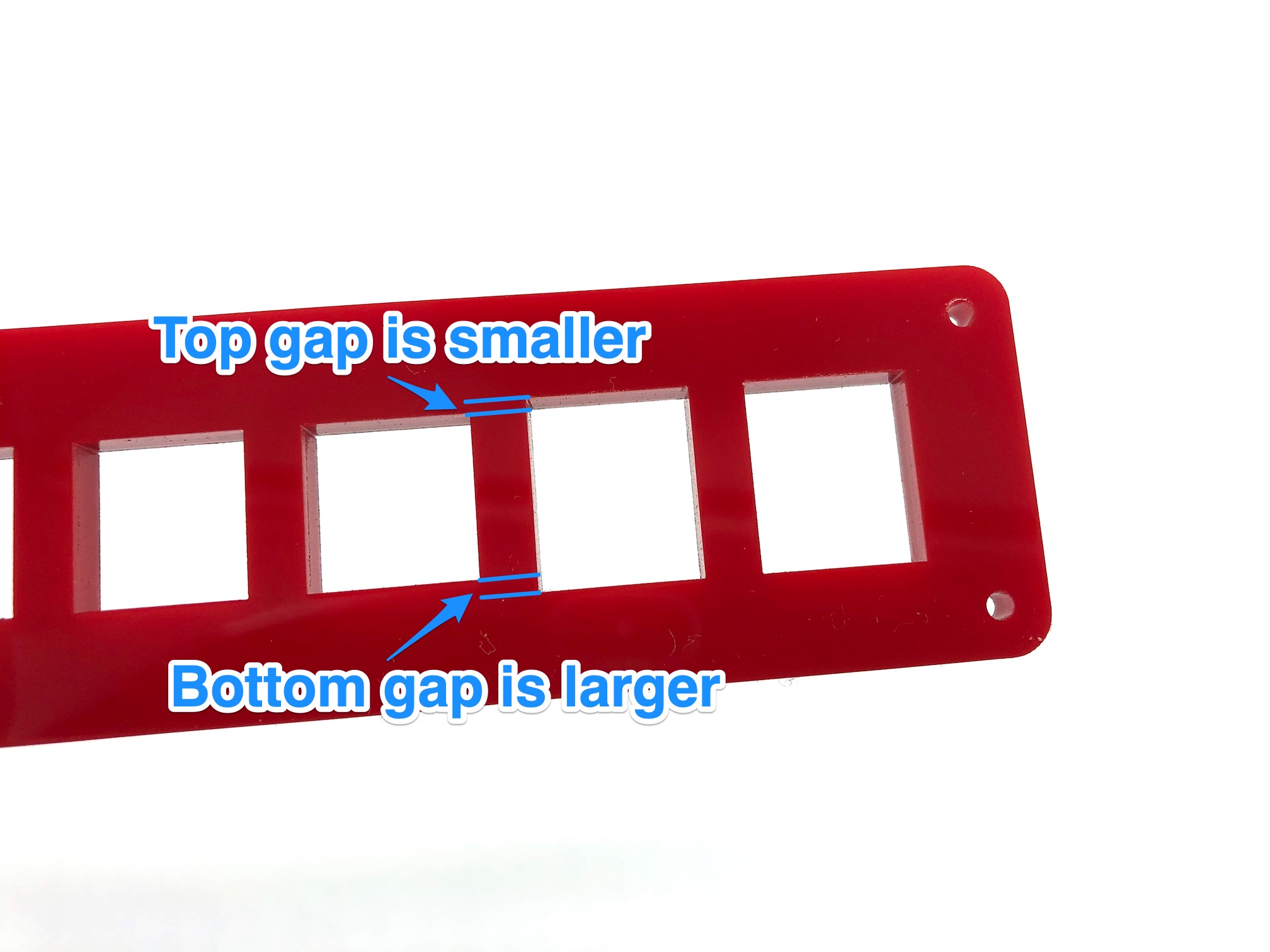
The orientation of the switch plate is important if you are going to be installing rotary encoders! In order for the encoders to not come in contact with the plate, make sure encoder cutouts are aligned as shown below. The encoder cutout is larger than the switch cutout at the top by 1mm and larger at the bottom by 1.5mm. If you are not careful, then the 3 bottom encoder pins may come in contact with the plate and be harder to install.
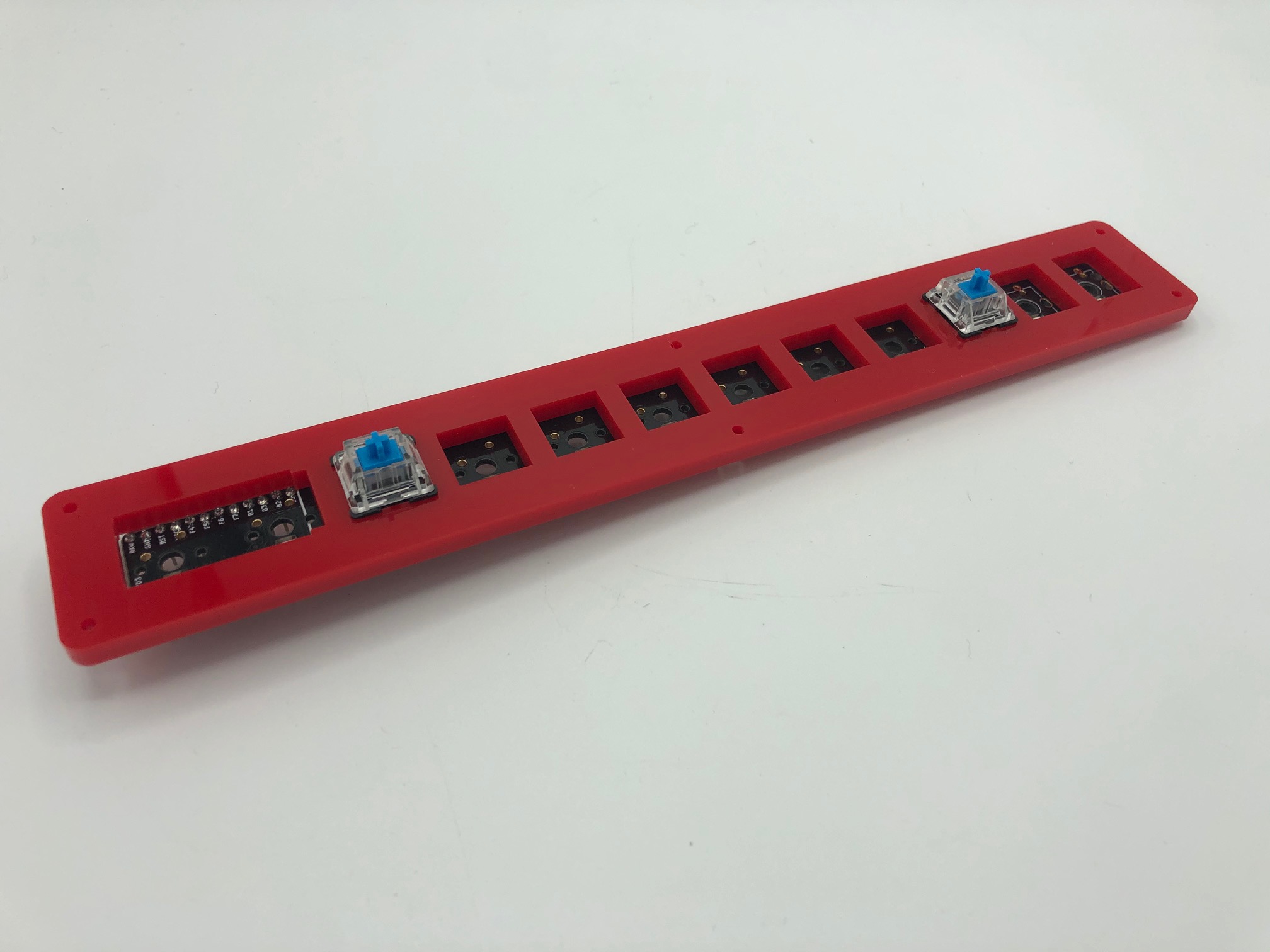
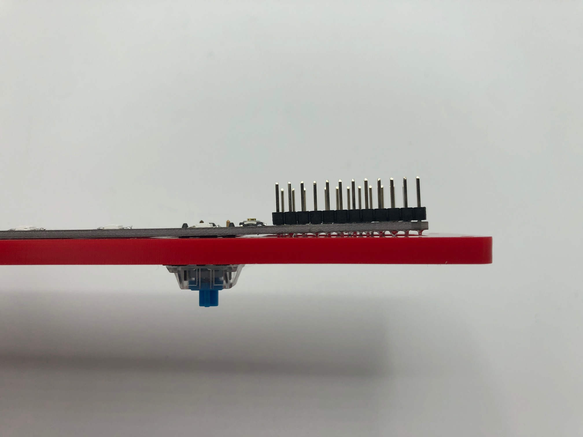
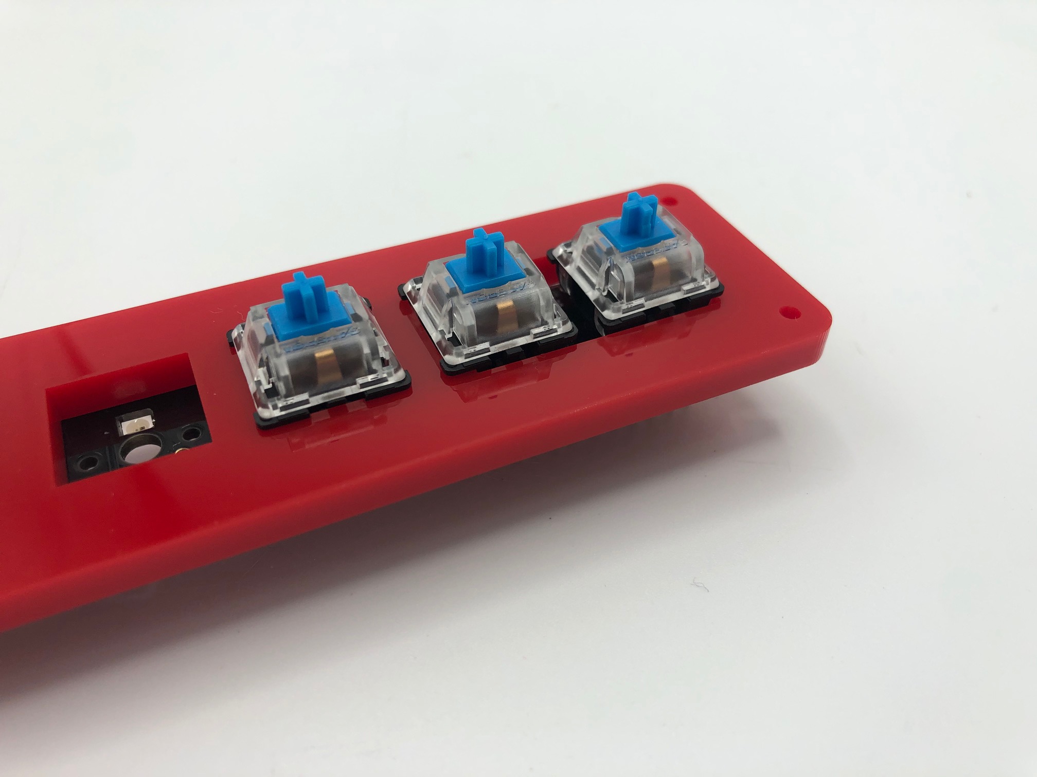
Insert two switches into the switch plate as shown and solder them in.
If you used Method 2 of soldering the header pins, you'll see that the portions of the header pins will stick out a bit a hit the underside of the switch plate. This will be okay, but it just makes soldering on the two switches there a bit more difficult.
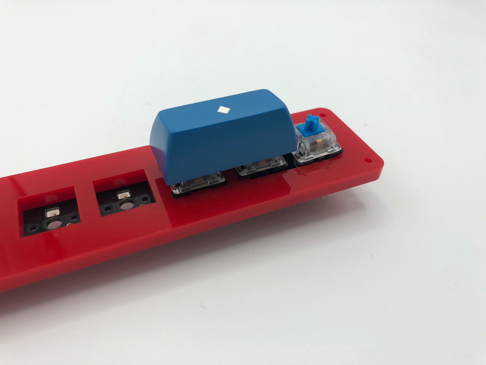
Add the two switches where the controller will end up.
Since those two switches won't have the plate to align them, if your switches are plate mount switches (i.e. they don't have the 2 plastic side legs), you will need to find some way to align them.
One way to align them is to use a 2u or 3u POS keycap.
Another way is to put keycaps on and wedge folded up piece of paper in between the keycaps.
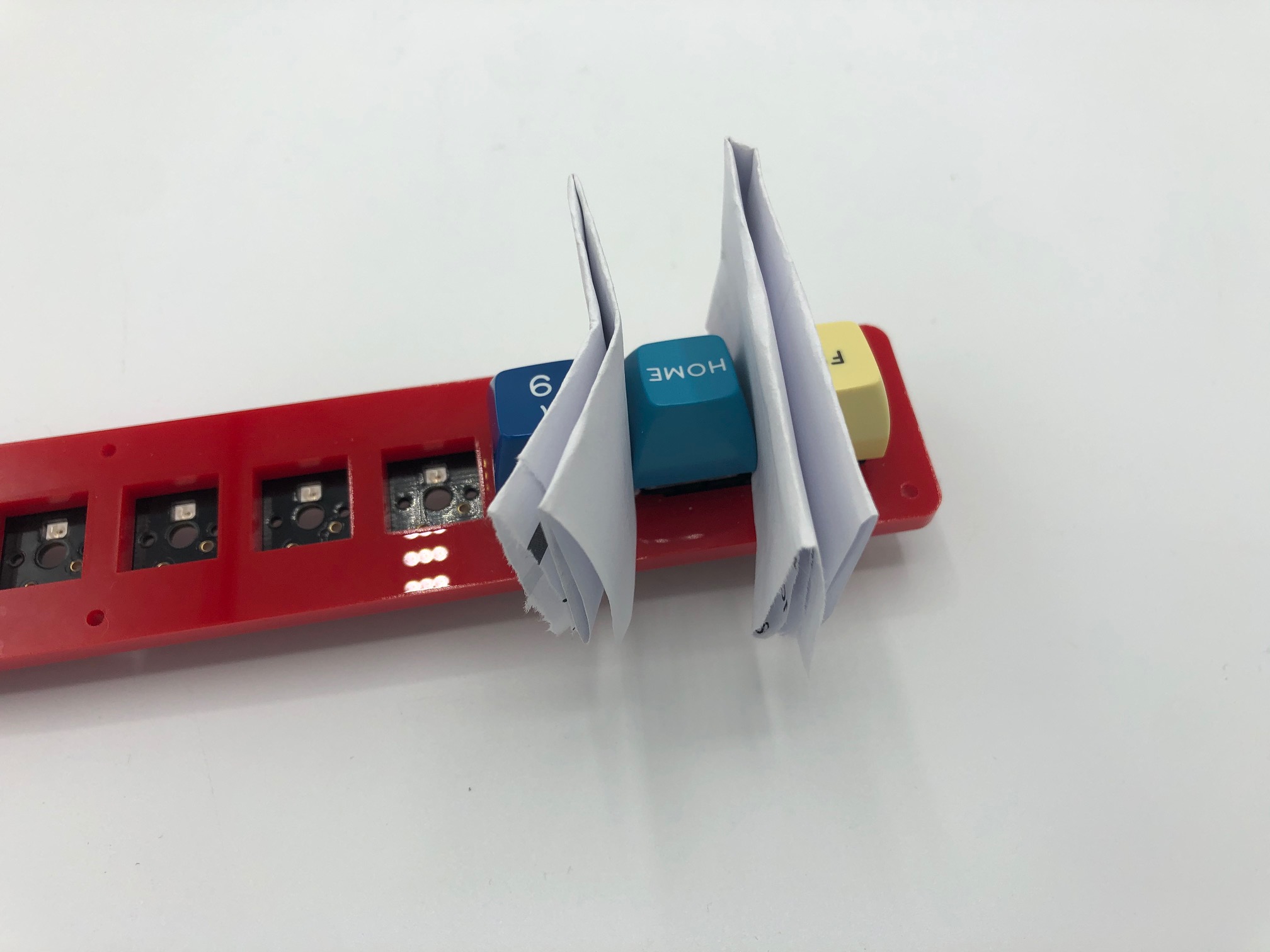
Once you've soldered in those two switches, solder the rest of the switches in.
Solder rotary encoders (optional)
Install the encoders onto the PCB.
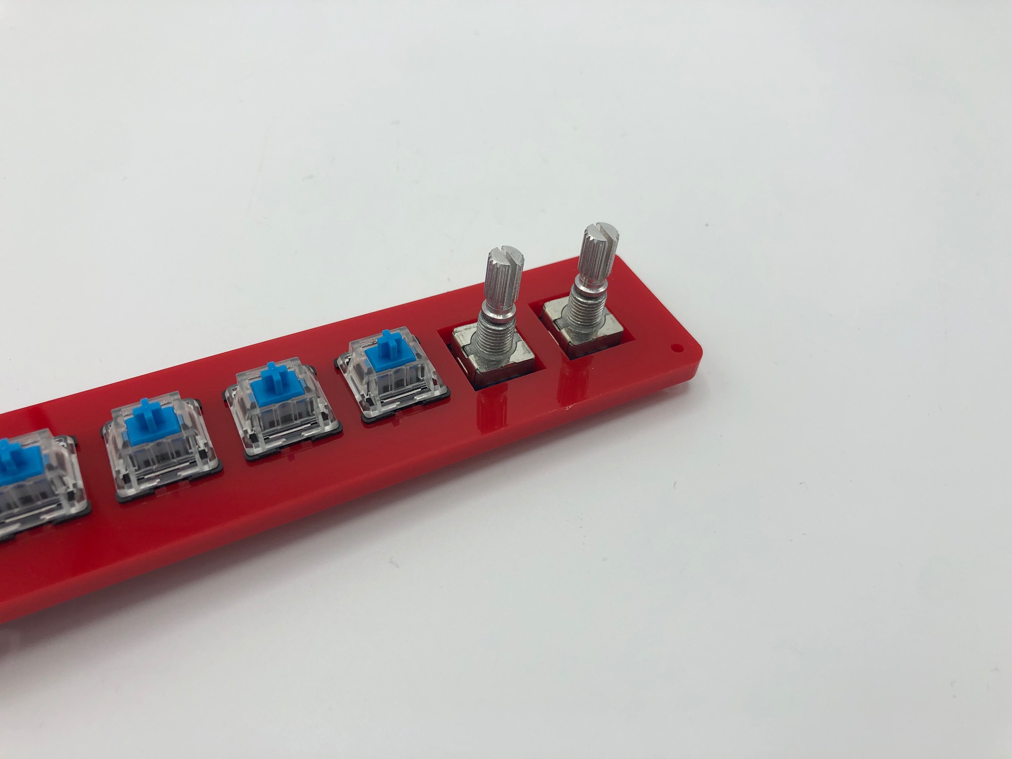
Flip the board over and solder the 2 pins at the top side of the encoder and the 3 pins at the bottom side. The 2 side legs do not need to be soldered to the PCB, although you may do so.
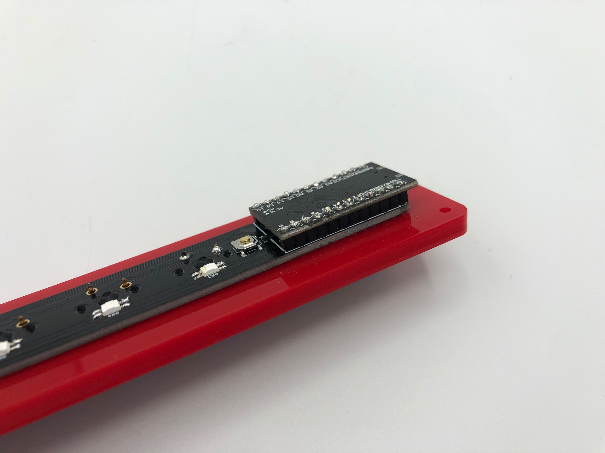
Solder controller
Place the controller onto the header pins.
Then, solder all of the header pins.
Clip the extra length of the header pins off.
Looking good, you're done with the soldering.
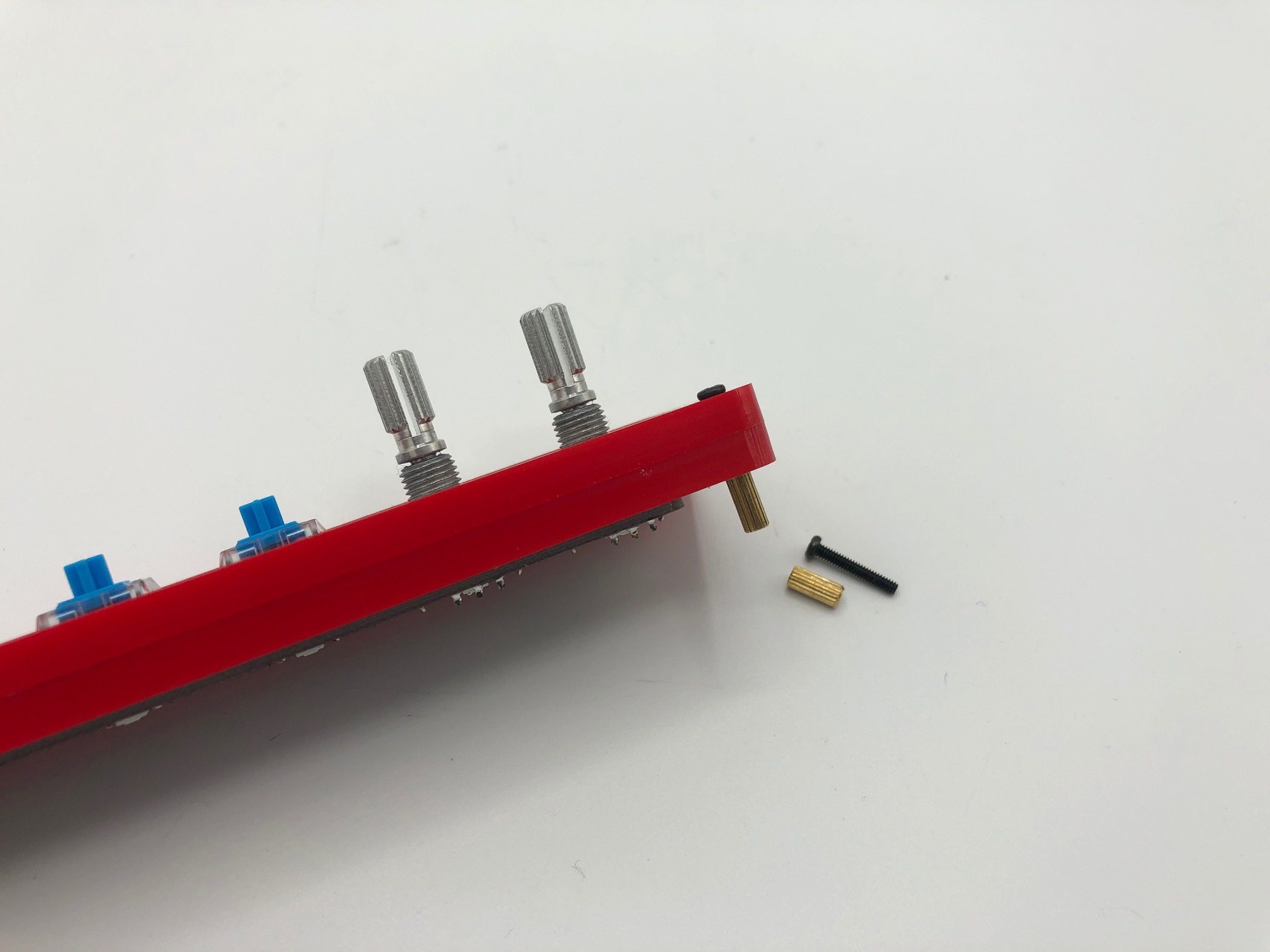
Assemble case
Insert a 12mm screw through the top of the top shell and the switch plate and attach a standoff from the bottom side of the plate:
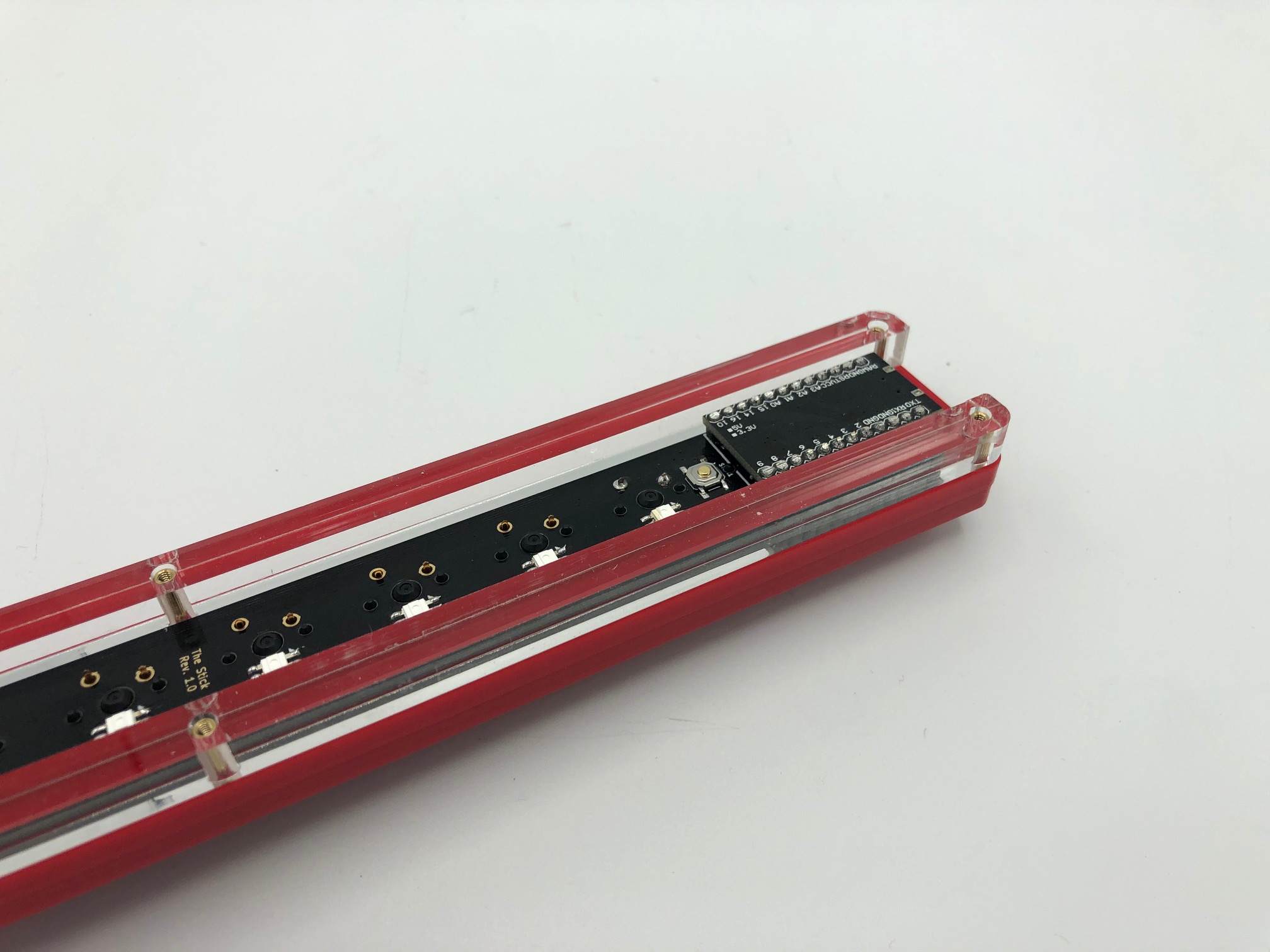
Repeat the process for the other 5 holes. Then place the middle layer over the standoffs.
Put bottom plate on and add the 8mm screws.
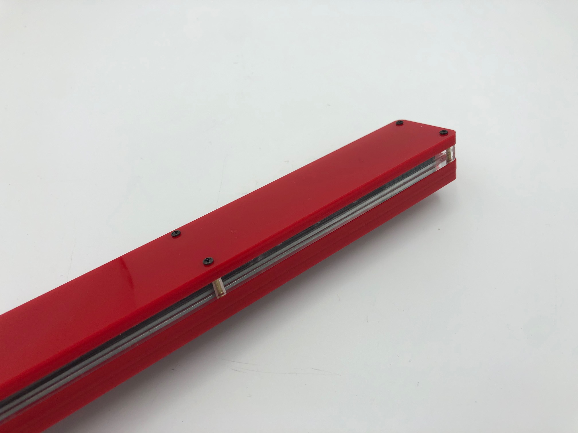
Put on some keycaps and knobs. You're done!