Quefrency Rev. 1
Parts List
Here's a list of parts needed for the build:
- 1 Quefrency PCB Kit
- 2 Reset Switches (included in kit)
- 2 4.7kΩ resistors (included in kit)
- 2 TRRS Jacks (included in kit)
- 47 1N4148 diodes - through hole (included in kit) and SMD diodes supported
- 1 Quefrency Case Plates
- 29 M2 6mm screws (included with plates)
- 14 M2 10mm standoffs (included with plates)
- 2 Arduino Pro Micros
- 1 TRRS Cable
- 1 Micro USB Cable
- PCB-mount MX stabilizers (2u)
- MX or Alps compatible keyswitches
- WS2812B Compatible RGB LED strip (optional, for underglow)
Build Steps
- Prepare components
- Solder components
- Solder diodes
- Solder push button
- Solder 4.7kΩ resistors (optional)
- Solder Pro Micro header pins
- Solder switches
- Flash Pro Micro
- Solder Pro Micro
- Solder RGB strip (optional)
Prepare Components
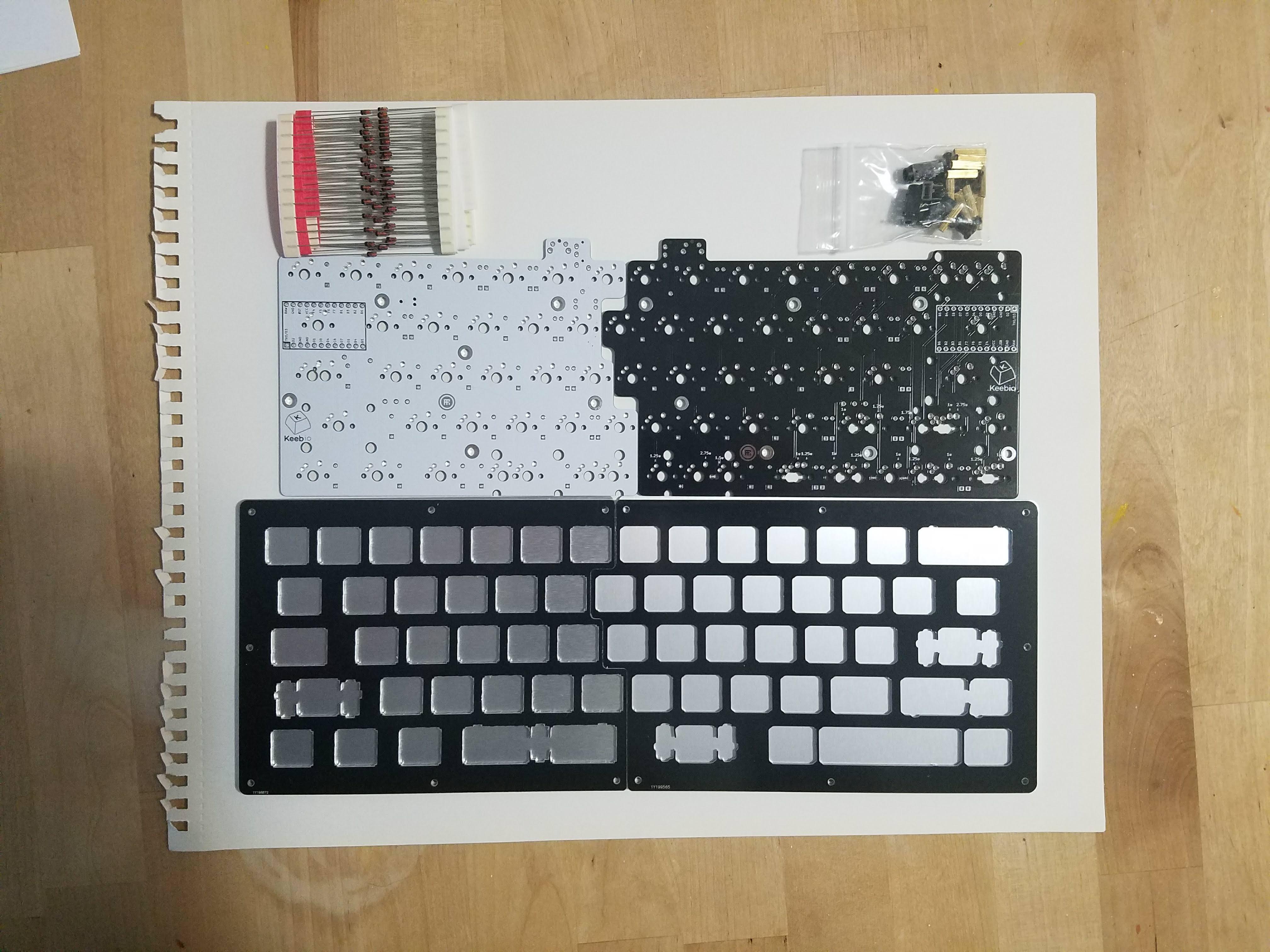
Get your parts all set and make sure you have all the components.
Make sure to let kitty know it's build time, if you don't she'll forget to disrupt you every step of the way.
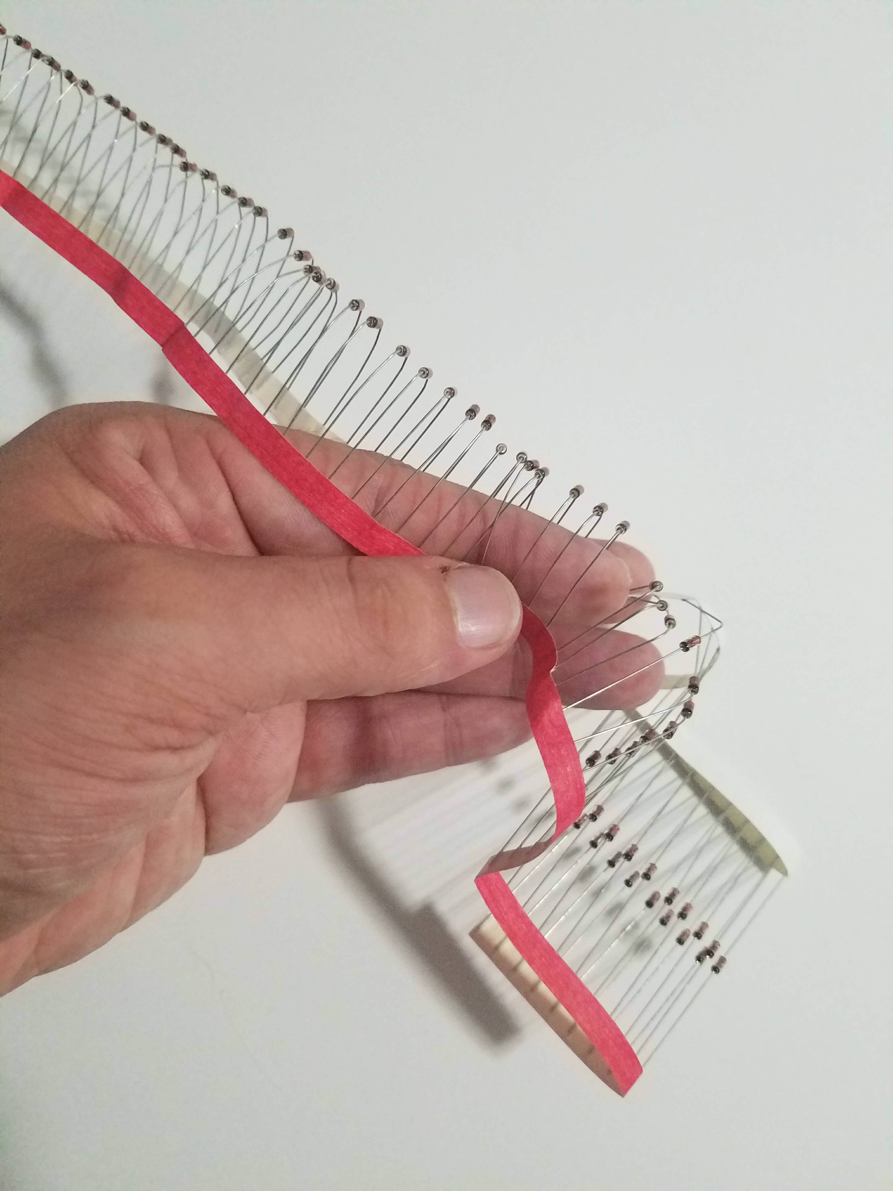
If you're using through hole diodes, bend 'em up. Here, I'm just bending it around my finger. Then tear the paper off carefully as not to bend them.
Solder diodes, reset push buttons, TRRS jacks
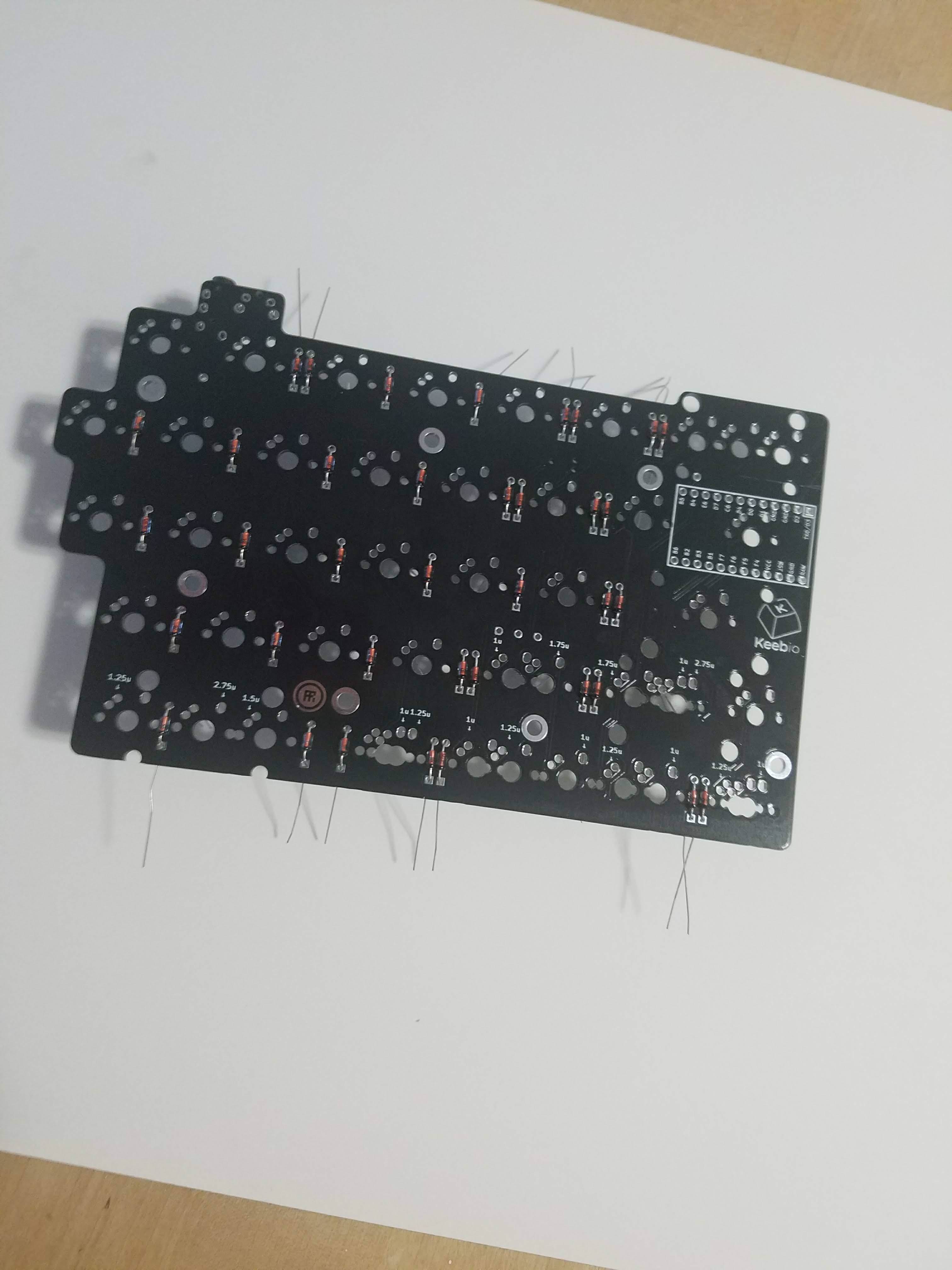
This way, if a diode goes bad, it's very simple to replace. If you choose to install them on the top, should any go bad, you will regret this, as you won't be able to replace the faulty component easily.
Insert the diodes. The orientation of all the diodes are the same, they are vertically oriented, with the band on the diodes facing towards the bottom, square pad.
Through-hole diodes will have a black band, SMD diodes have a white band.
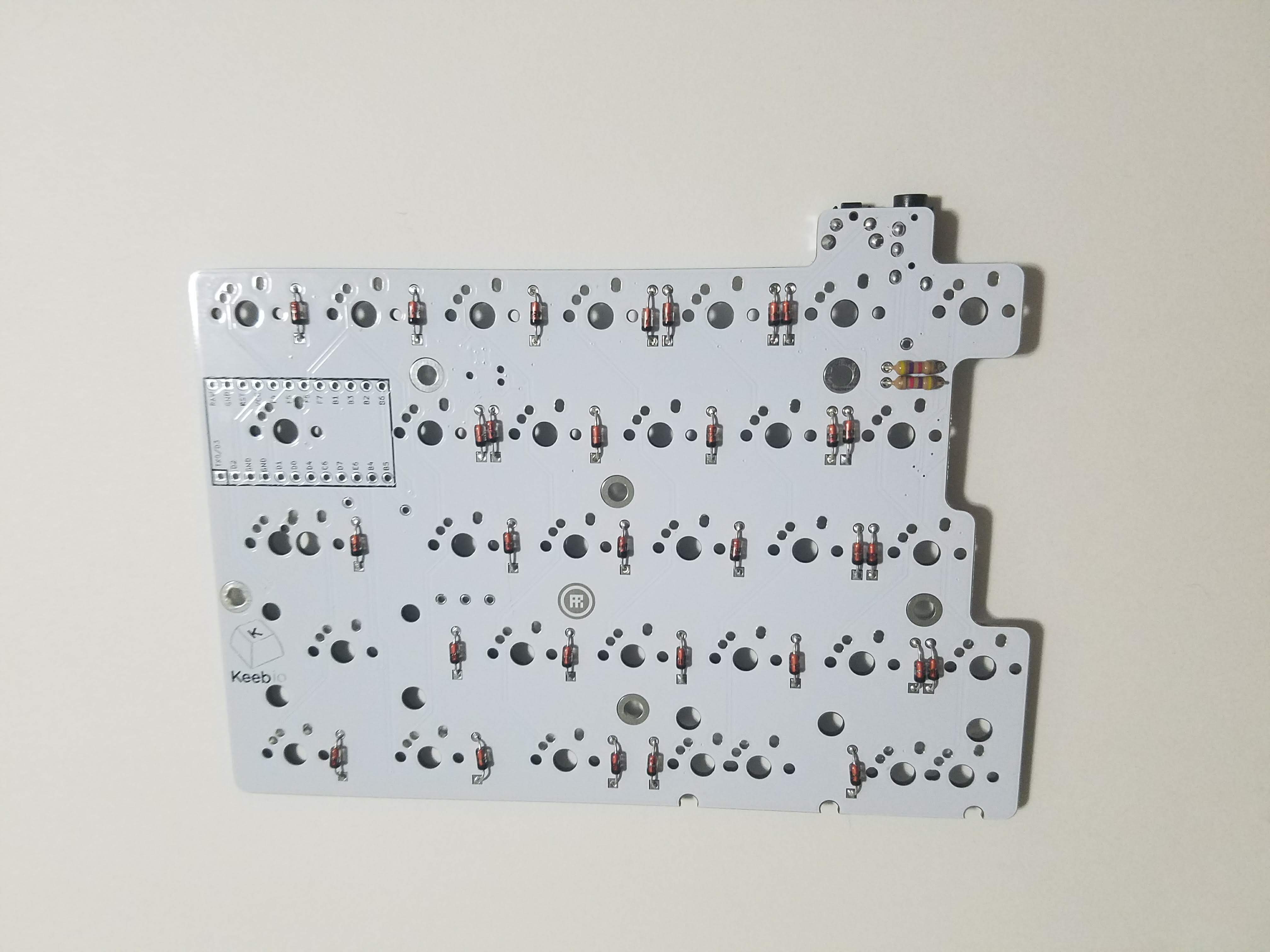
All the diodes installed on the left PCB.
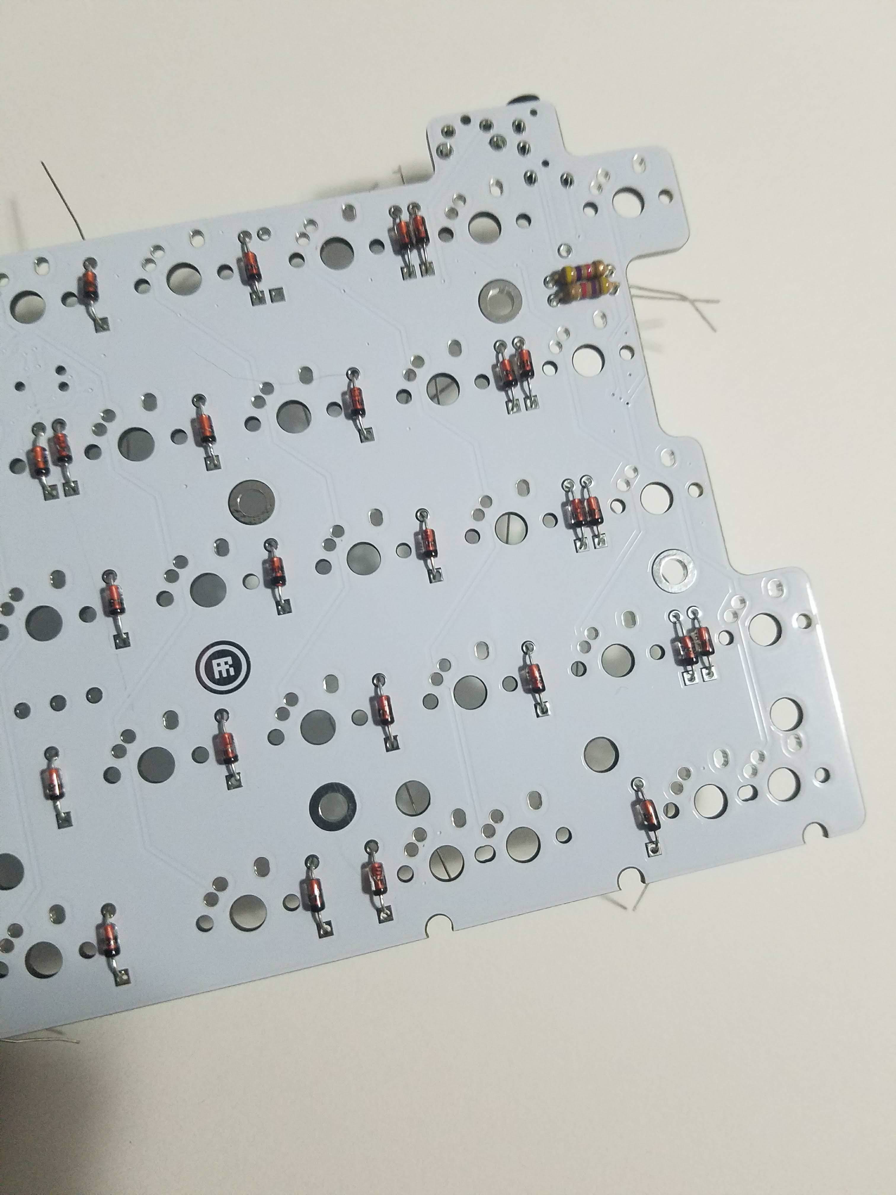
After installing the diodes, add your TRRS jacks and reset buttons.
Solder I2C resistors (optional)
Add your 4.7k ohm resistors for I2C on the left half. There are no resistors for the right half. Resistors also do not have a polarity, so the orientation doesn't matter when placing them.
The default firmware uses serial communication between the two halves using a single pin of the TRRS cable. Serial communication only allow for communication between two parts, which is fine for almost all builds.
However, in the future, there might be additional parts that you can add, like a numpad, OLED screen, etc. To support this, the communication protocol would need to be switched over I2C, which can support multiple devices. Additionally, the latency between halves is lower using the I2C protocol, which can help if you are a fast typer.
To add support for I2C, all you need to do is add the 2 4.7kΩ resistors to one of the halves (other half does not need them). Also, it doesn't hurt to add these resistors if using serial communication.
tl;dr: Adding this is optional, but you might as well do it as it's only 2 more components to solder.

Repeat the same process with the diodes, TRRS jack, and reset switch with the right half. Remember no I2C resistor slots on this side, as they're only needed on one half. Then, take a moment to pet kitty before she hates you for ignoring her.
Solder Pro Micro header pins
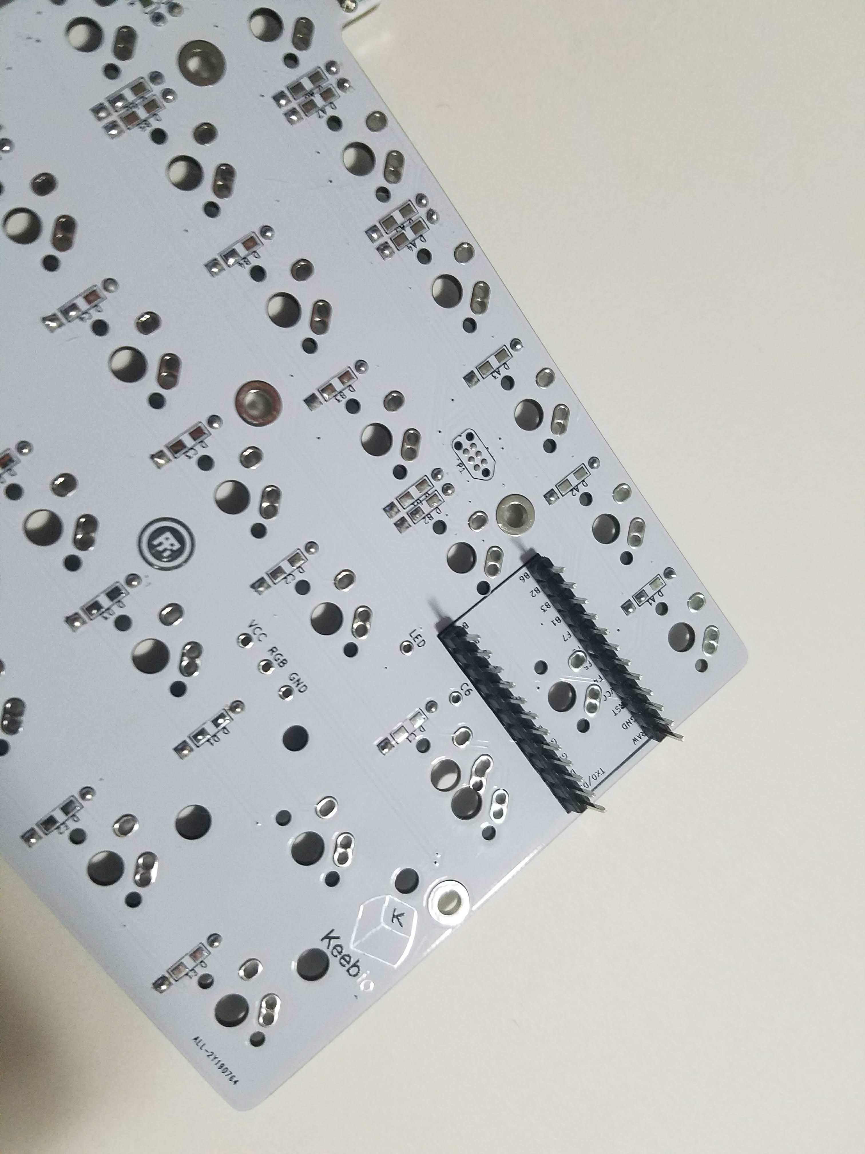
Solder on the header pins for the Pro Micro.
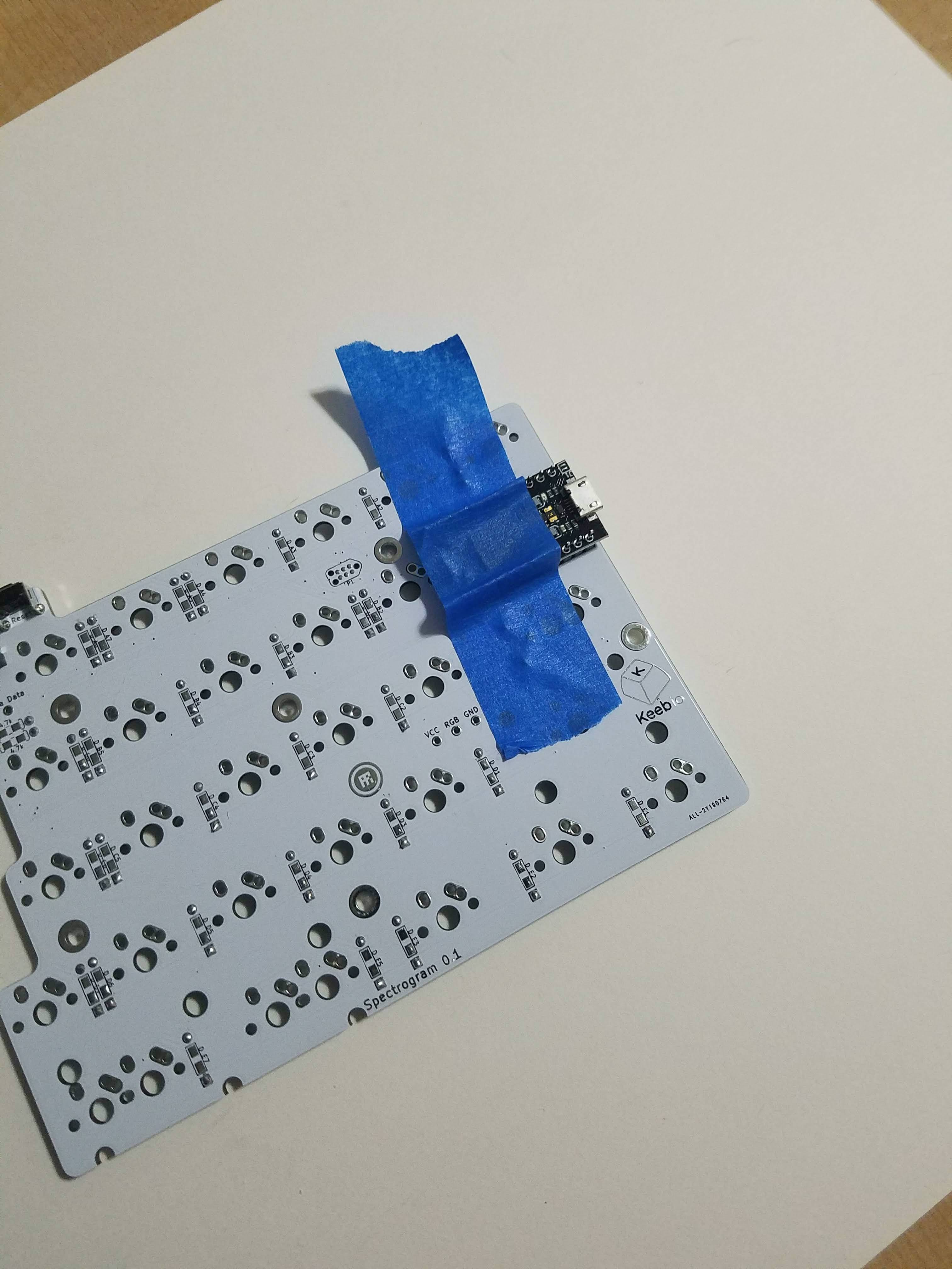
You can use the PM to get the alignment set, and/or tape it there to keep it from rocking to one side or the other, then solder the 4 corner pins on the top of the board. Do not solder the pro micro to the PCB.
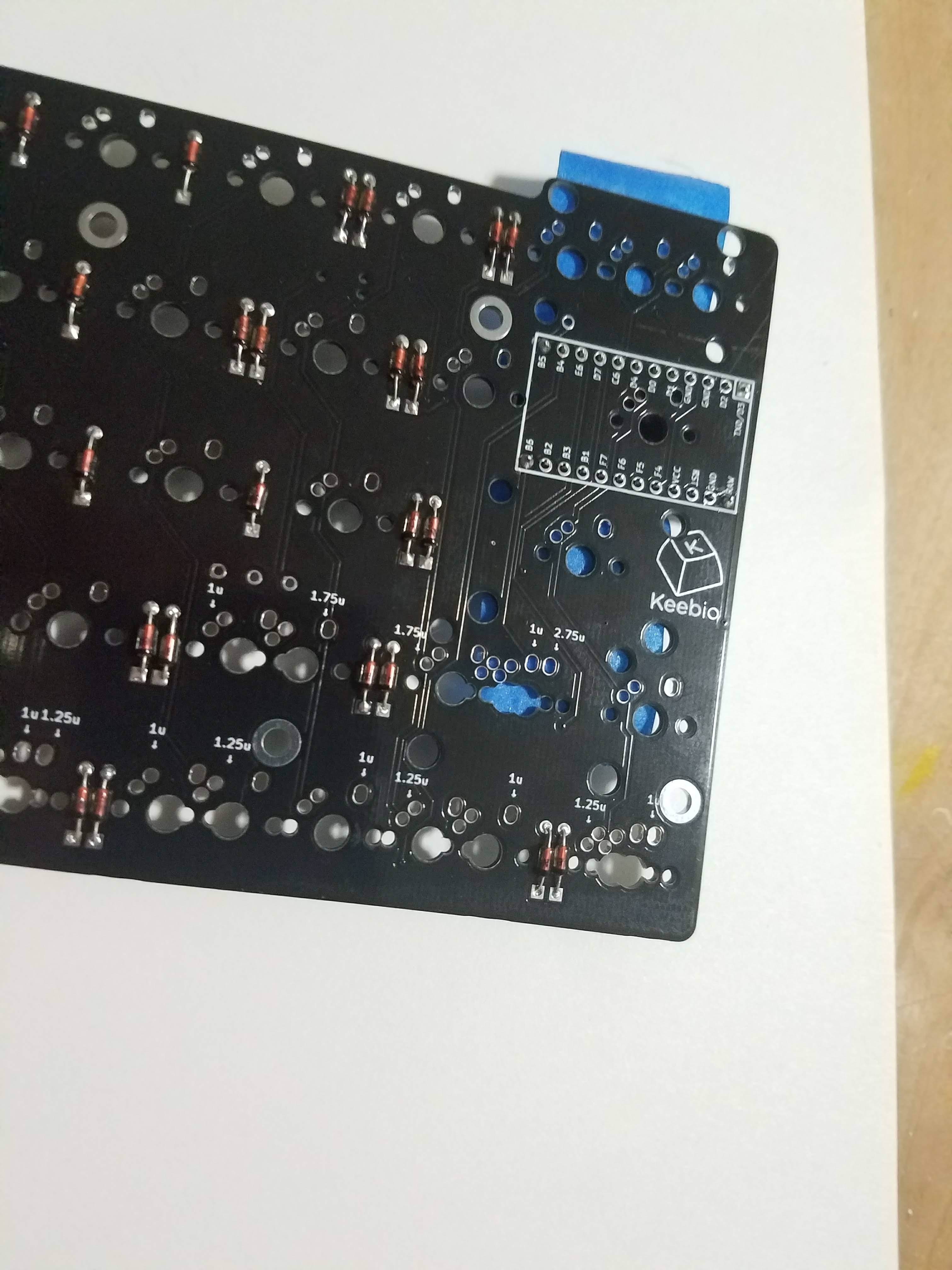
After the 4 corners are soldered in place, remove the PM. You don't want to space out and start soldering it to the pins, so just get it out of there.
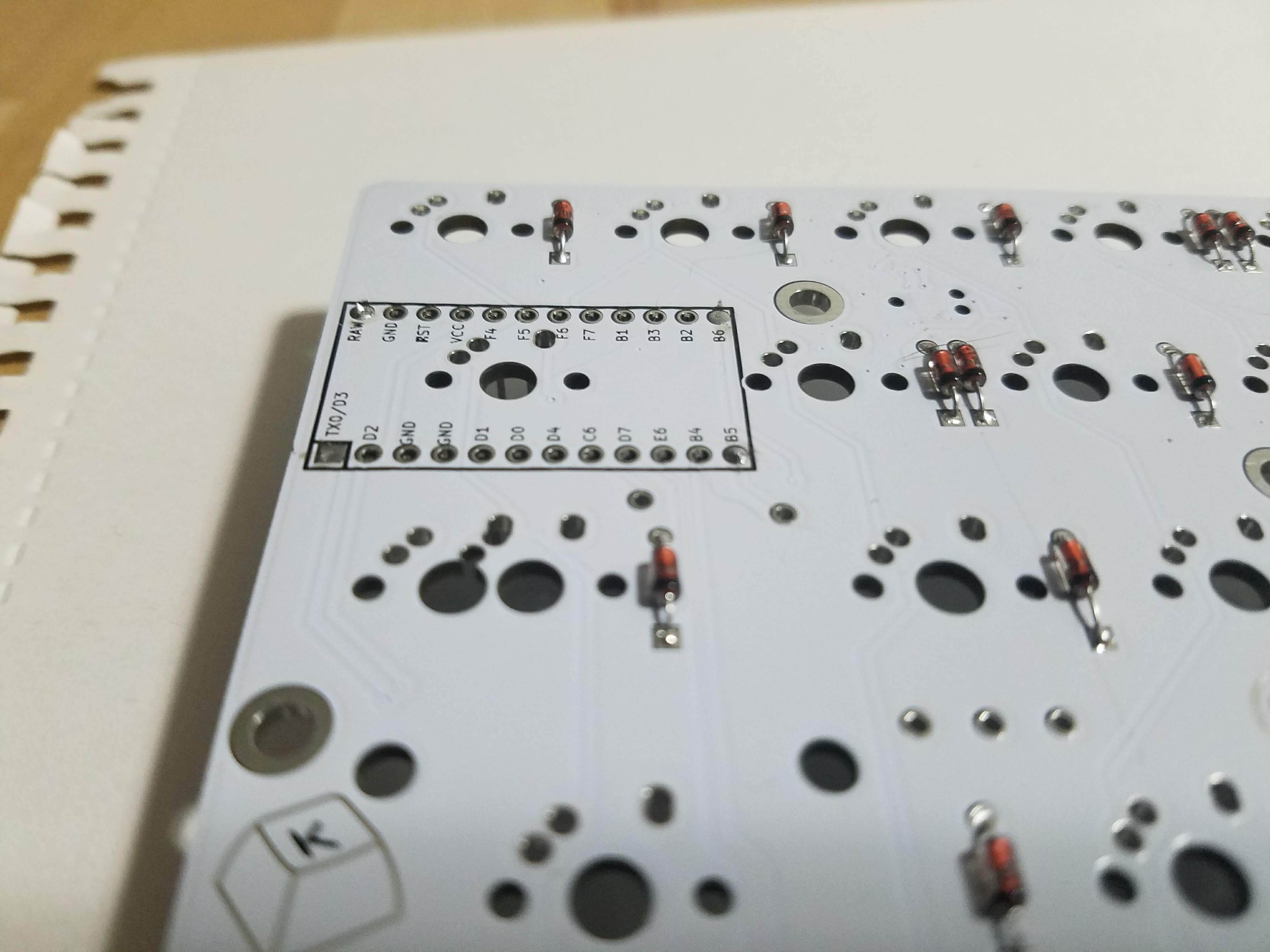
Finish soldering the remaining pins on each half, with the PM safely set aside.
Add stabilizers
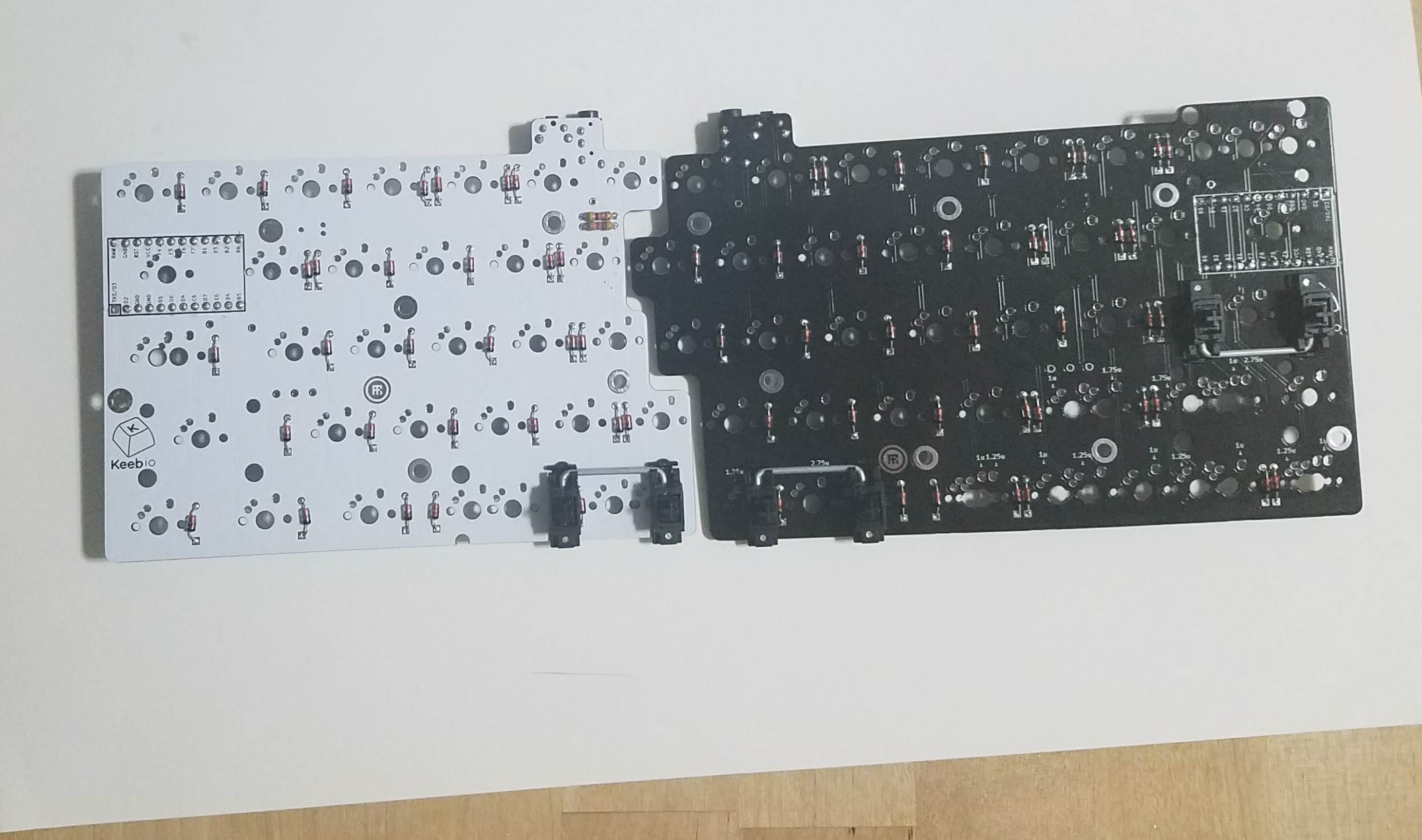
Add stabilizers to the keys you want to stabilize.
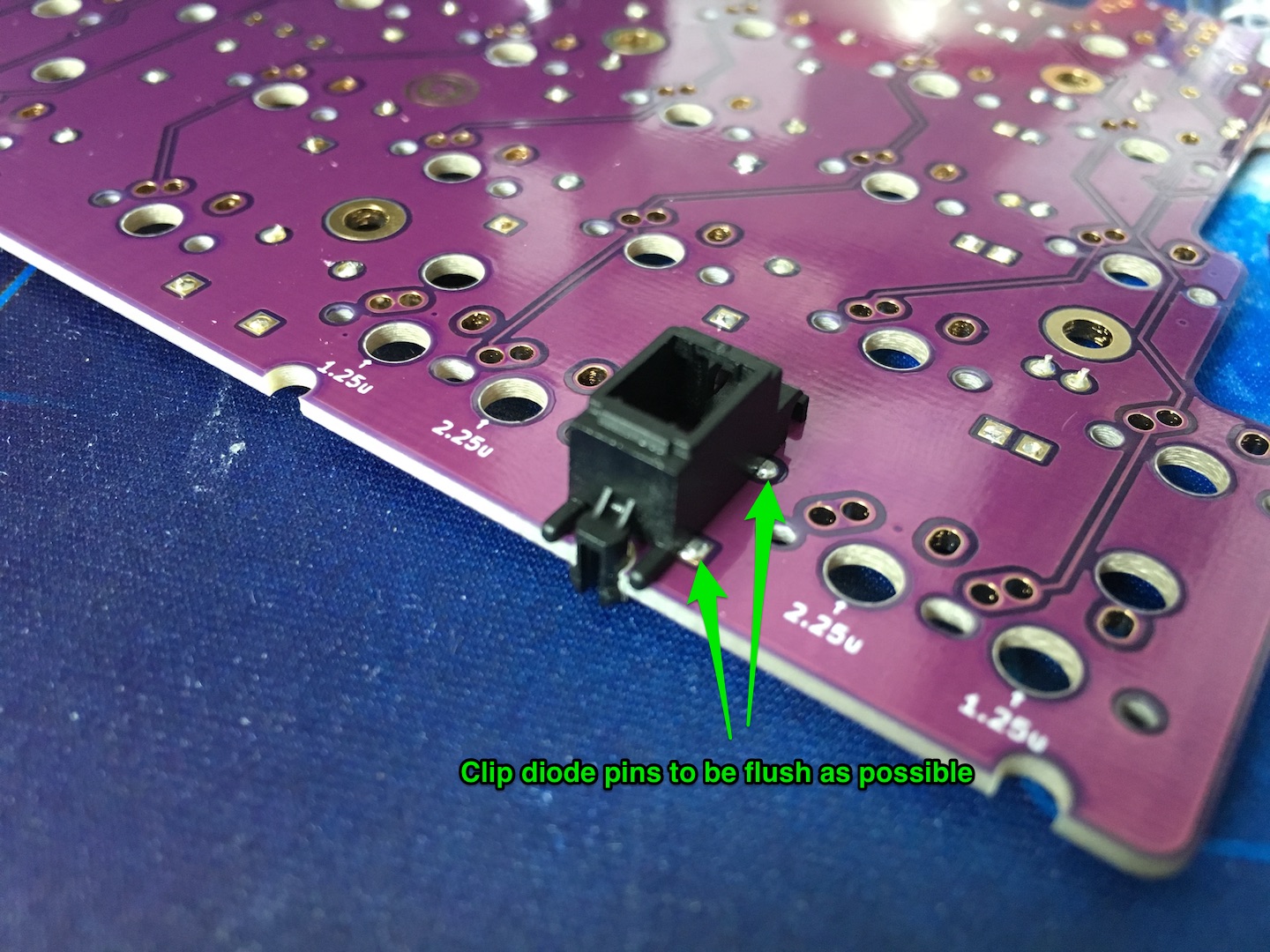
For the Rev. 1.0 left PCB, one of the stabilizer mounts sits right next to a diode. If using through-hole diodes, make sure that the diode legs for spot shown below are clipped as flush as possible, so that the stabilizer can clip in correctly.
This issue has been fixed on the 1.1 PCB.
Add switches
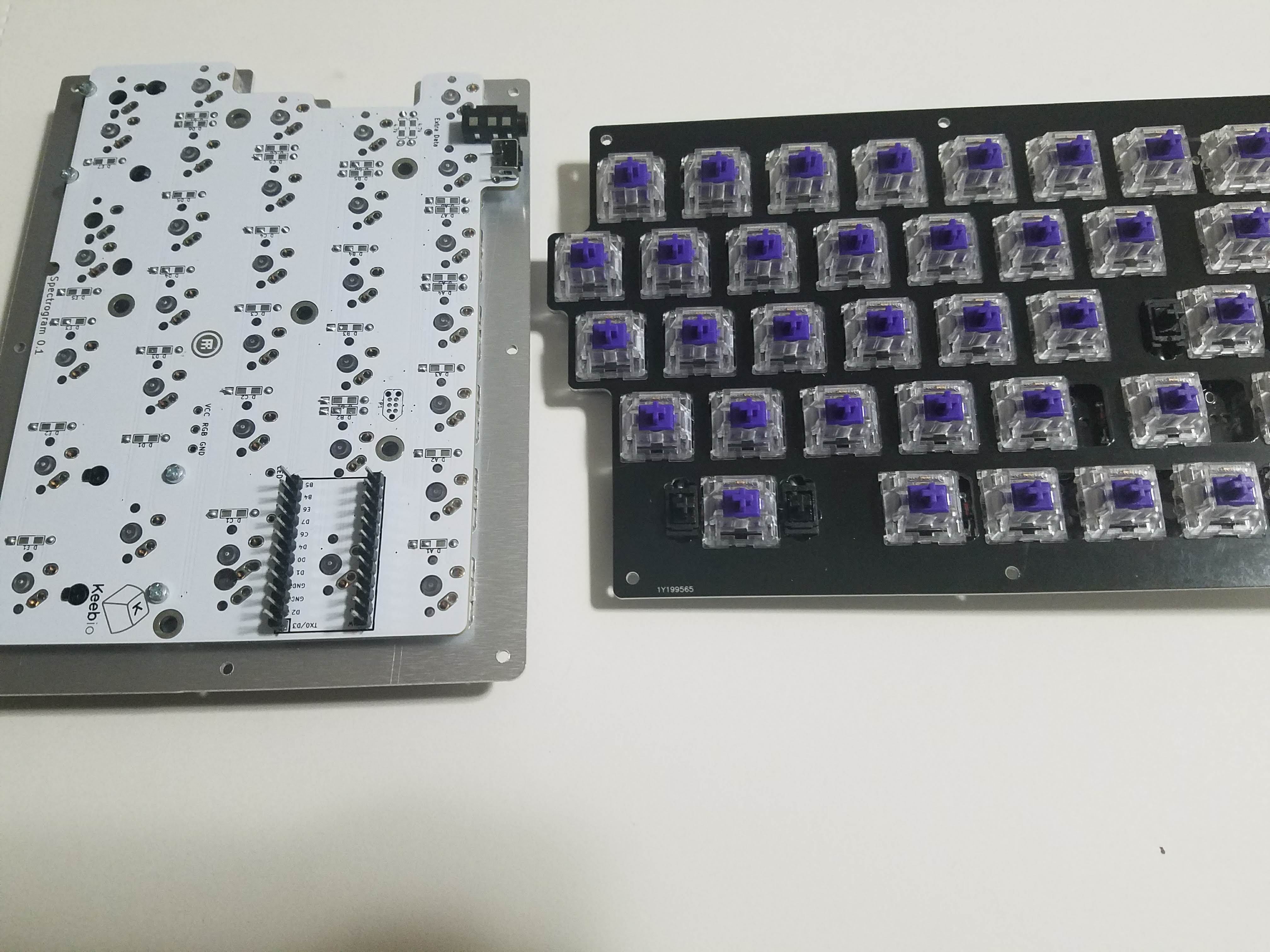
Time to add the switches. Put a few switches into the corners of the switch plate and then attach the switches to the PCB. Make sure the switches are pushed all the way down onto the PCB.
Due to the multiple layout options, it may be helpful to put keycaps on the switches to make sure everything is in the correct slots, however, the layout options are labelled on the topside of the PCB.
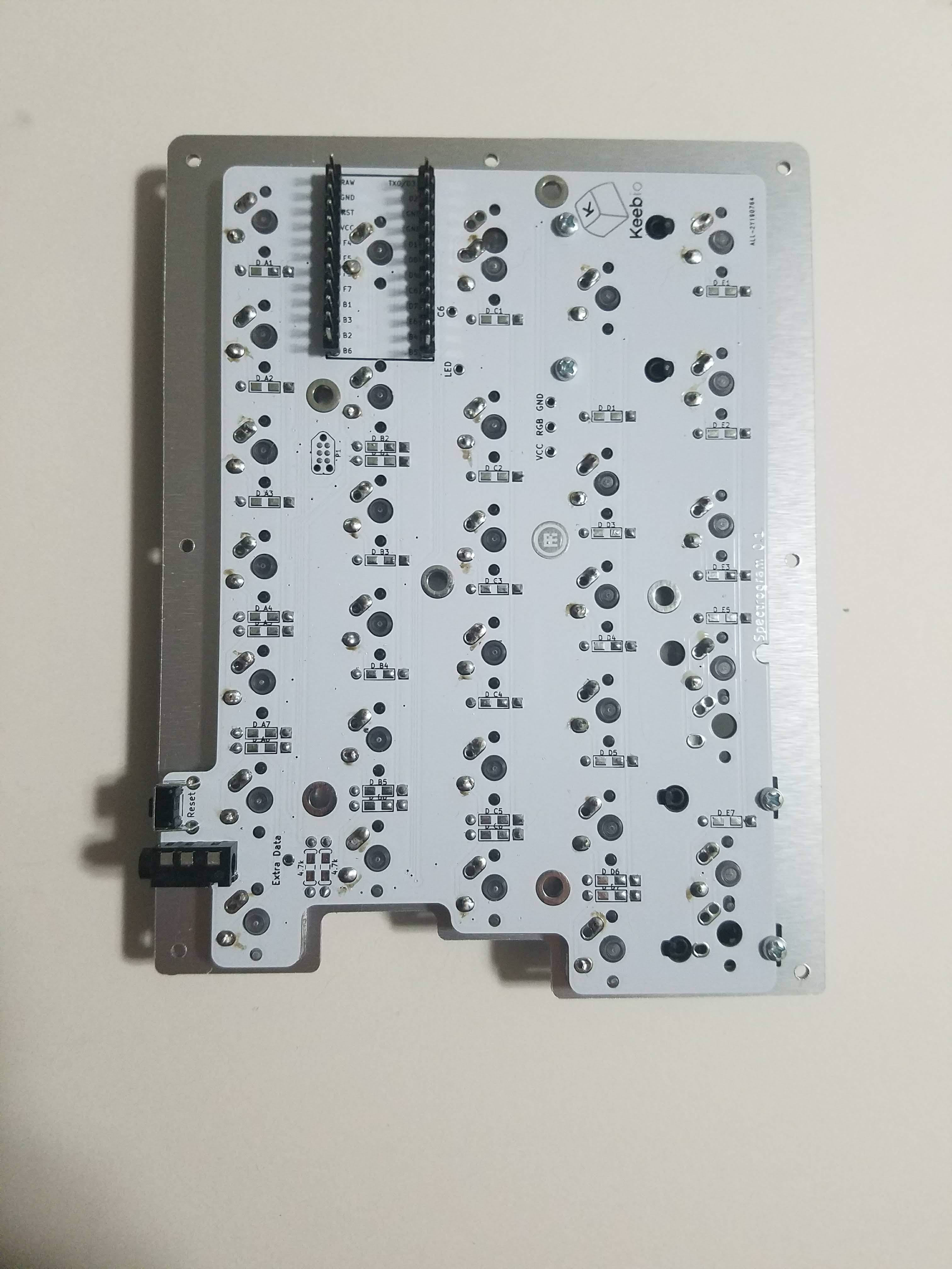
All the switches installed and soldered in.
Test/flash Pro Micro
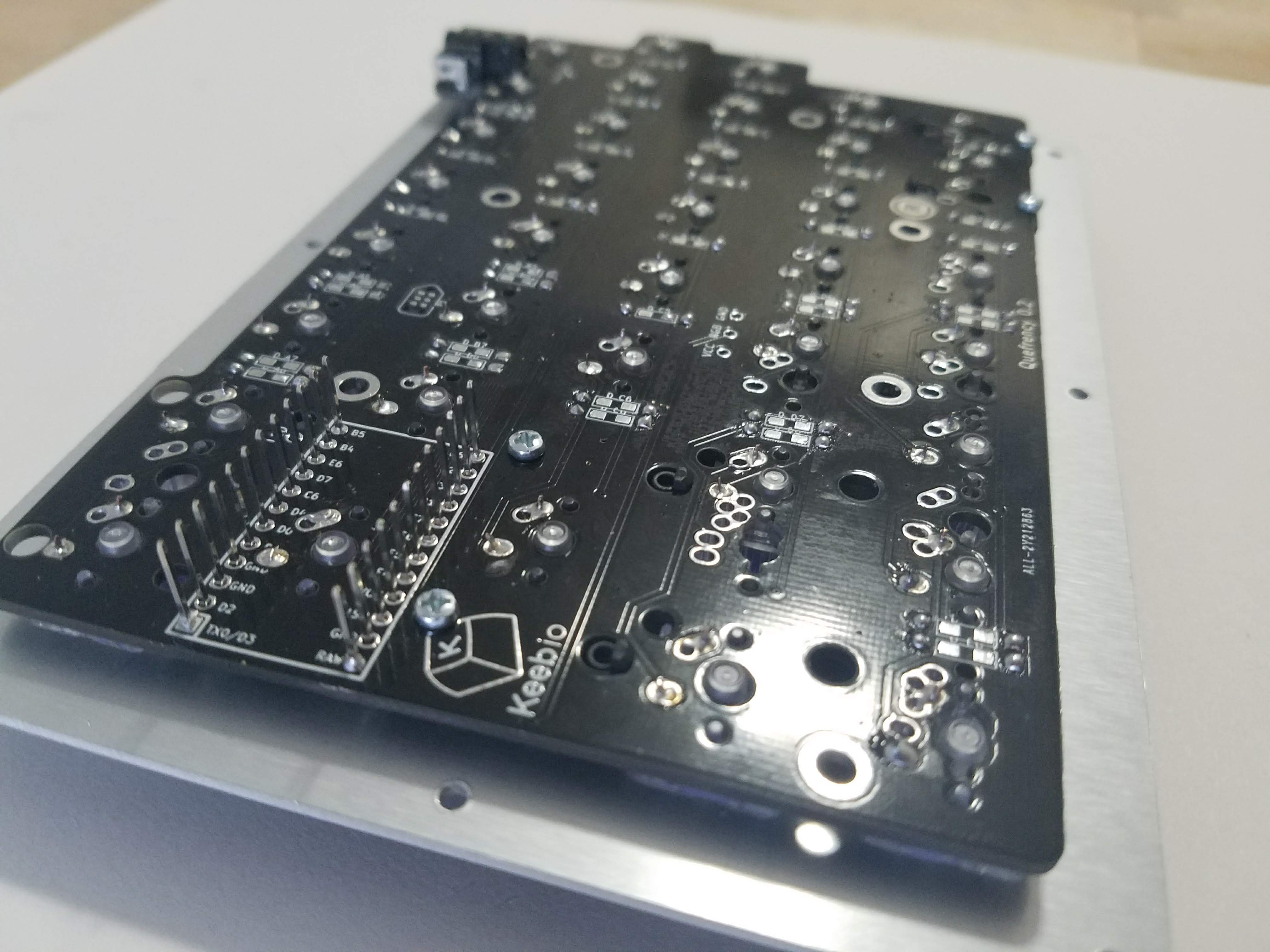
Time to install the Pro Micro now that the switches have been soldered in.
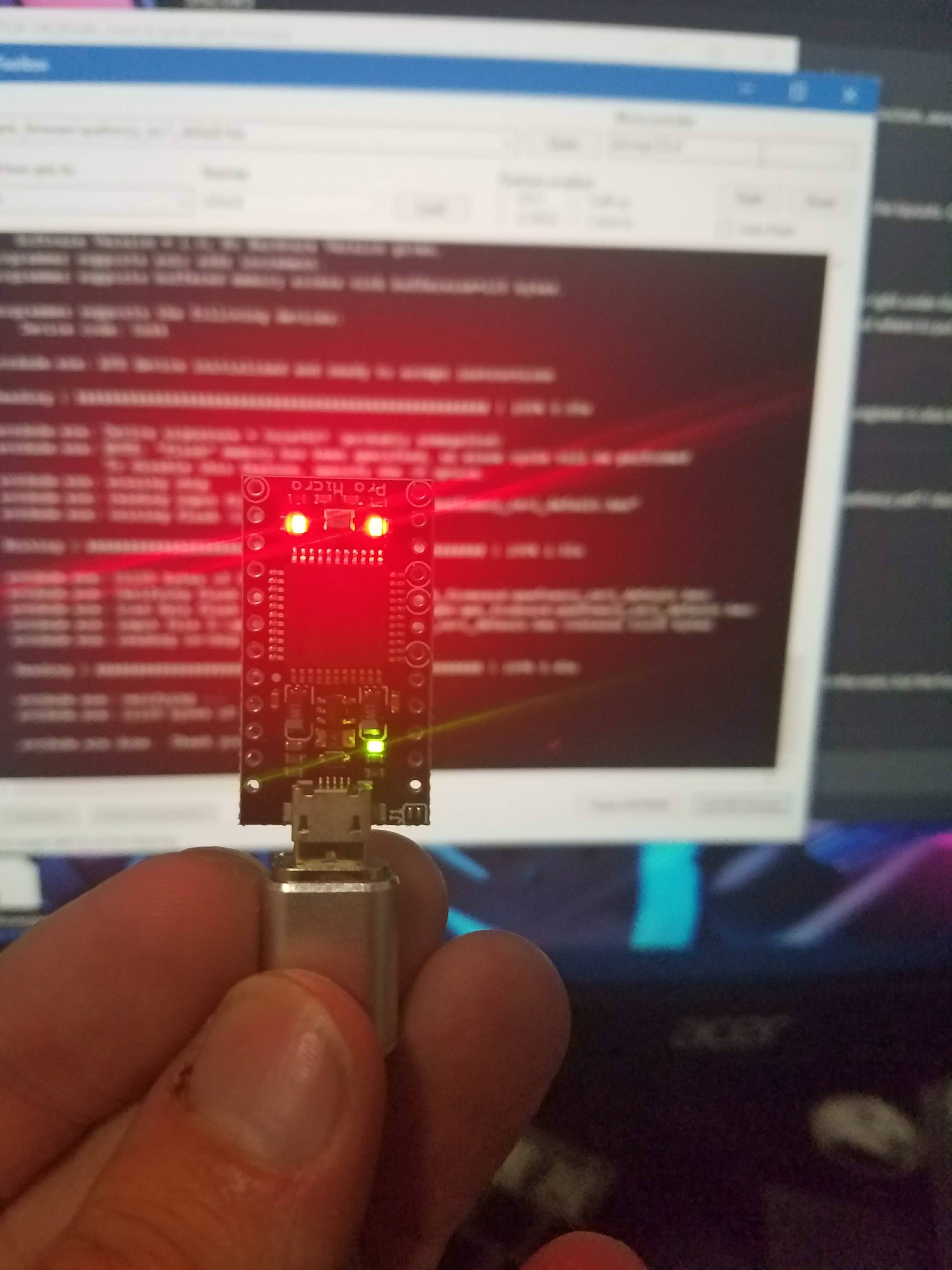
Flash those pro micros! We want to be sure they work before we install them.
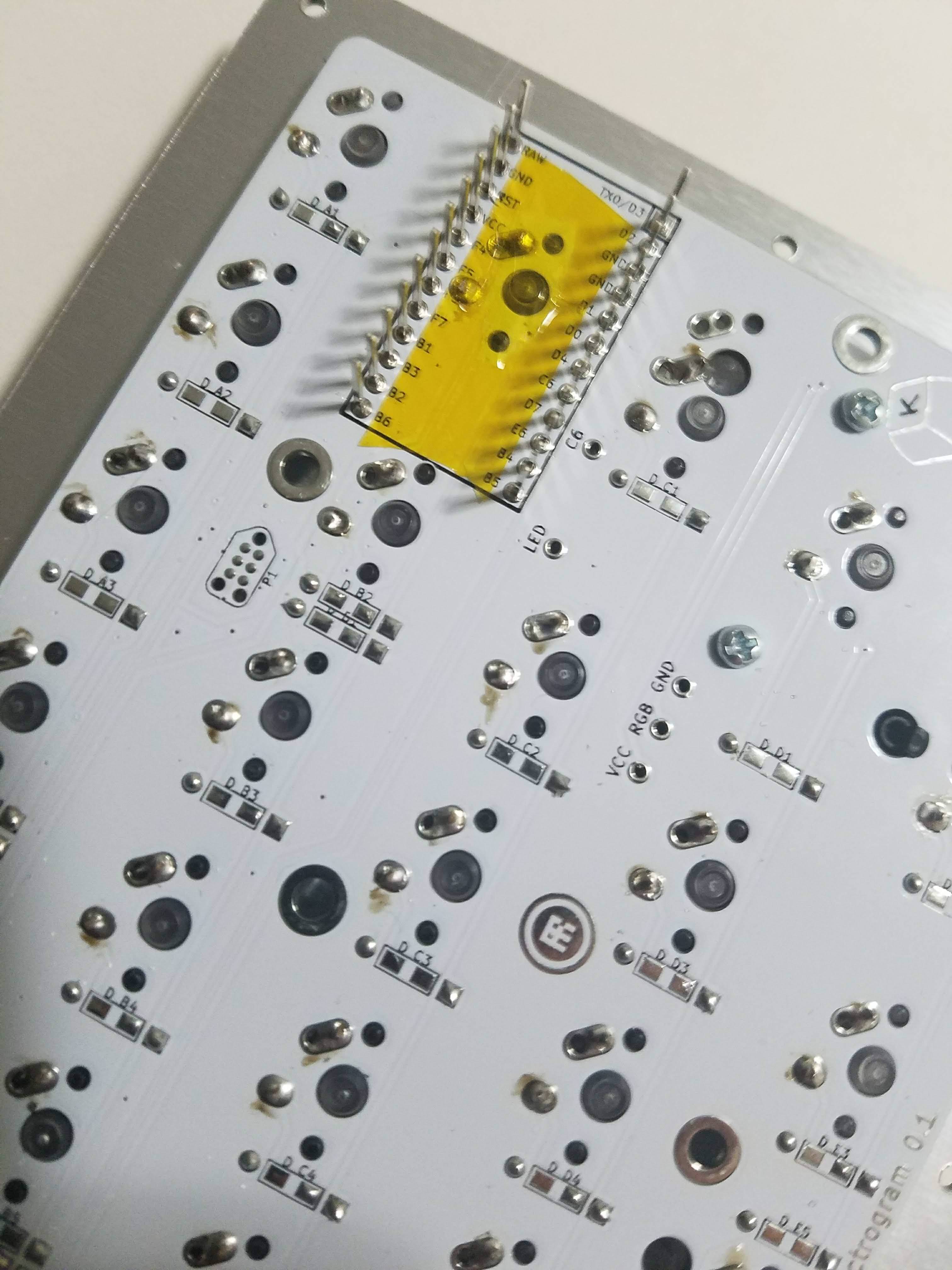
To make sure that the switch pins don't touch the Pro Micro, clip them flush with the PCB. Afterwards, add Kapton or electrical tape on top of it.
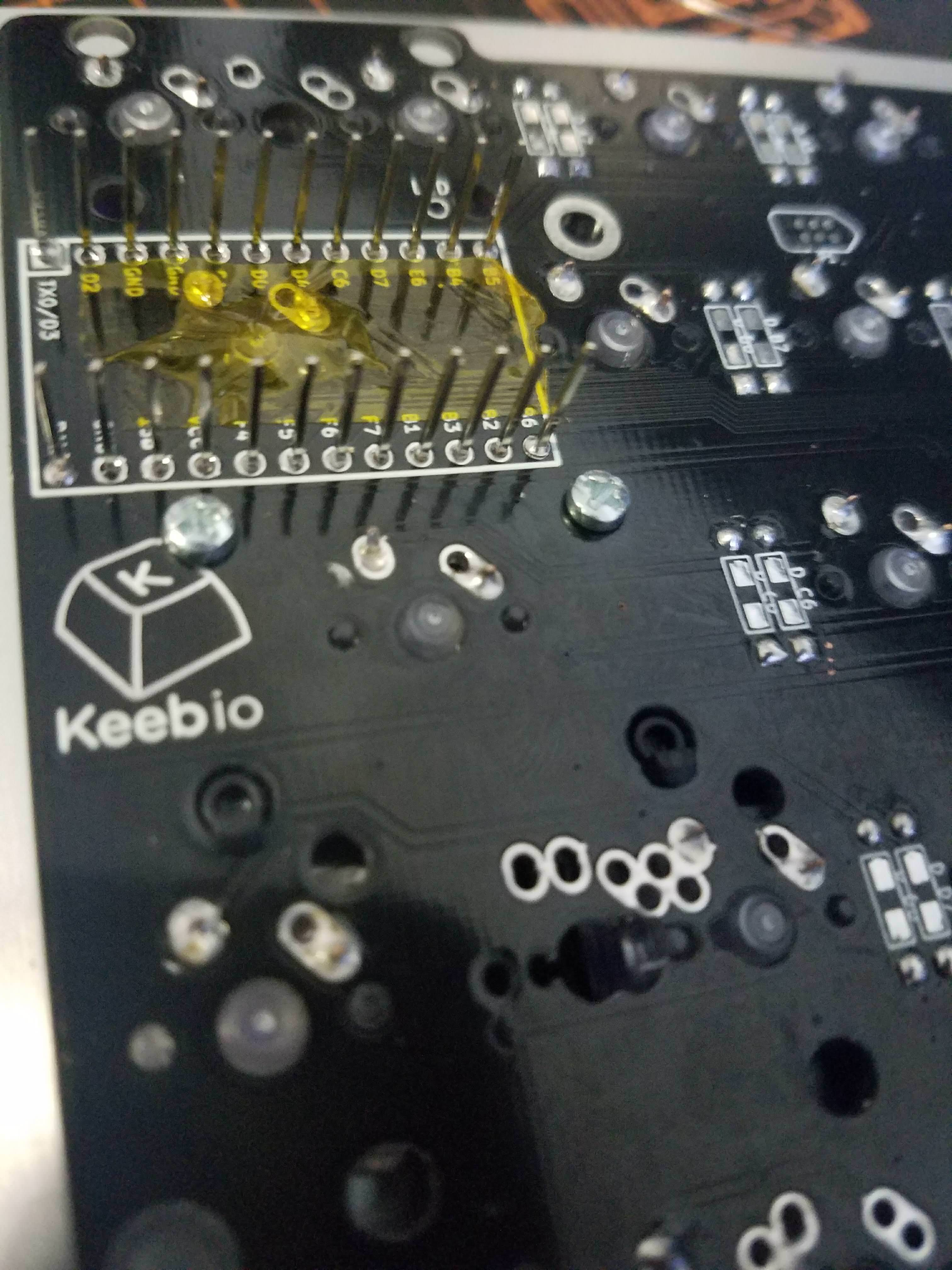
Solder Pro Micros
Place the Pro Micro on the header pins. Match the PM pinouts to the pinouts on the PCB.
Don't install it backwards, it won't work that way, and there's no software solution to fix that.
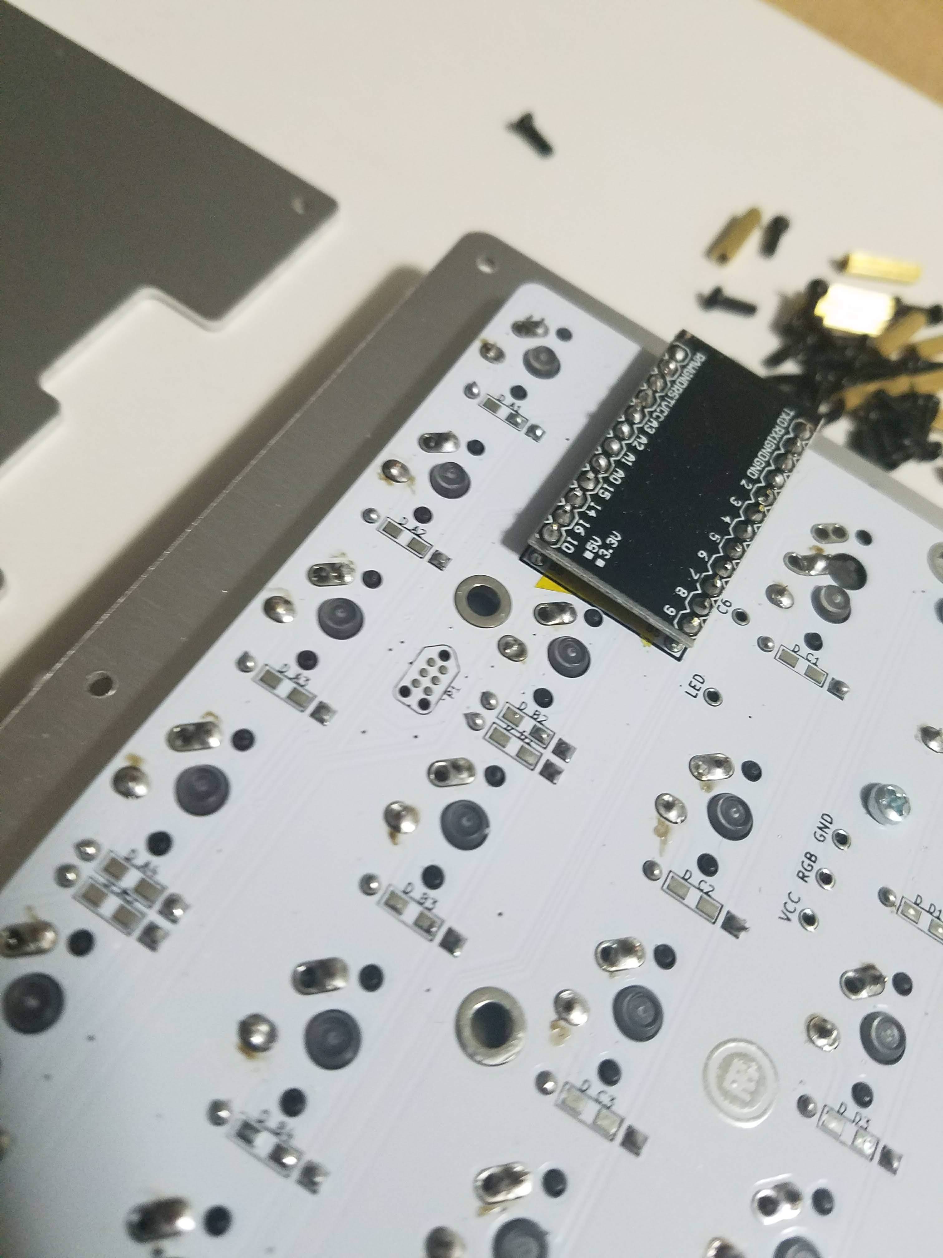
Trim down the pins with a flush cutter after it's soldered, then repeat on the other half.
Not shown in these pictures, but add electrical tape or Kapton tape on top of the Pro Micros and TRRS jacks to prevent the metal portions of them from touching the bottom plate.
Assemble case
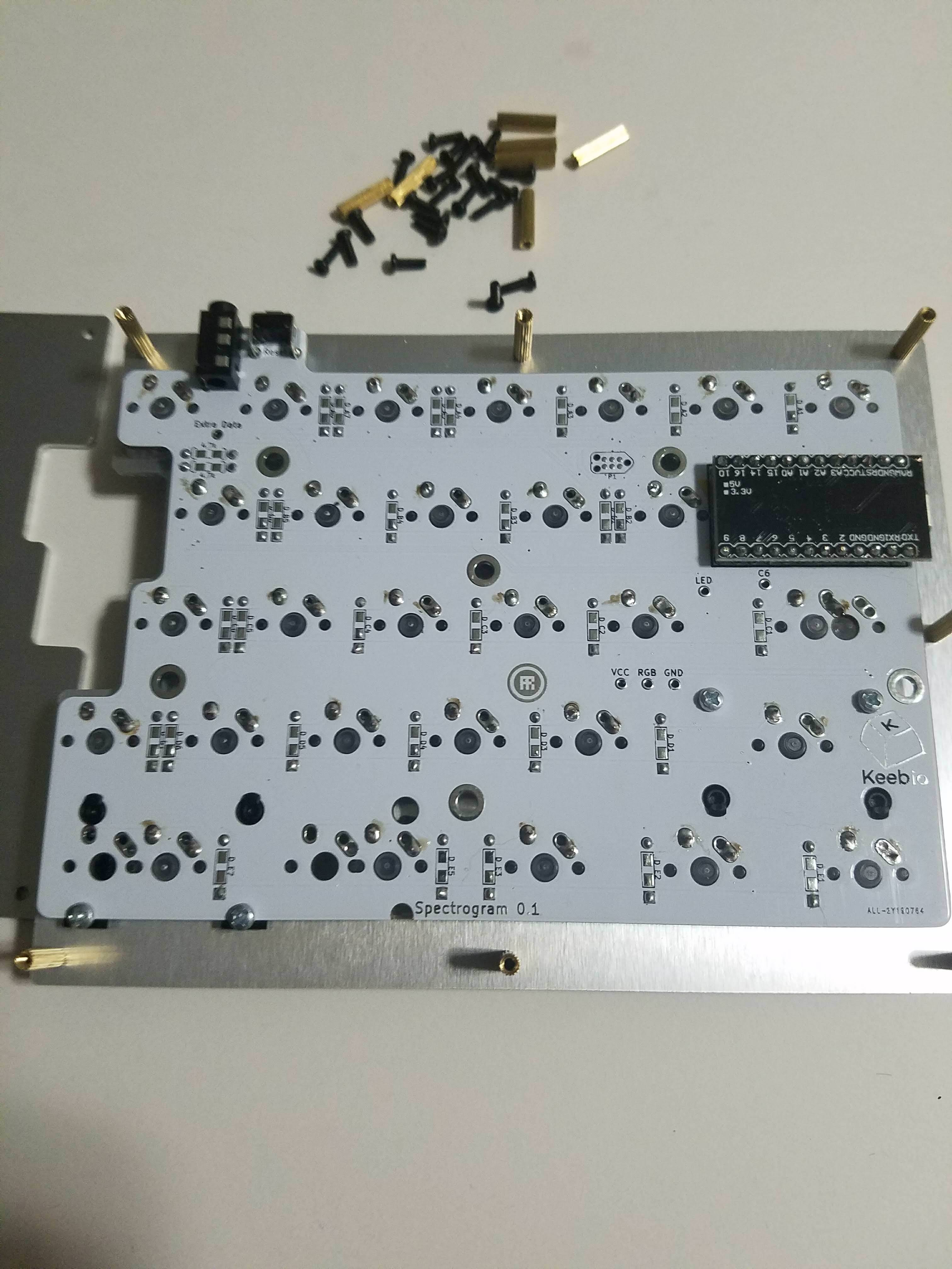
Assemble the case by adding screws, standoffs, and bottom plates.
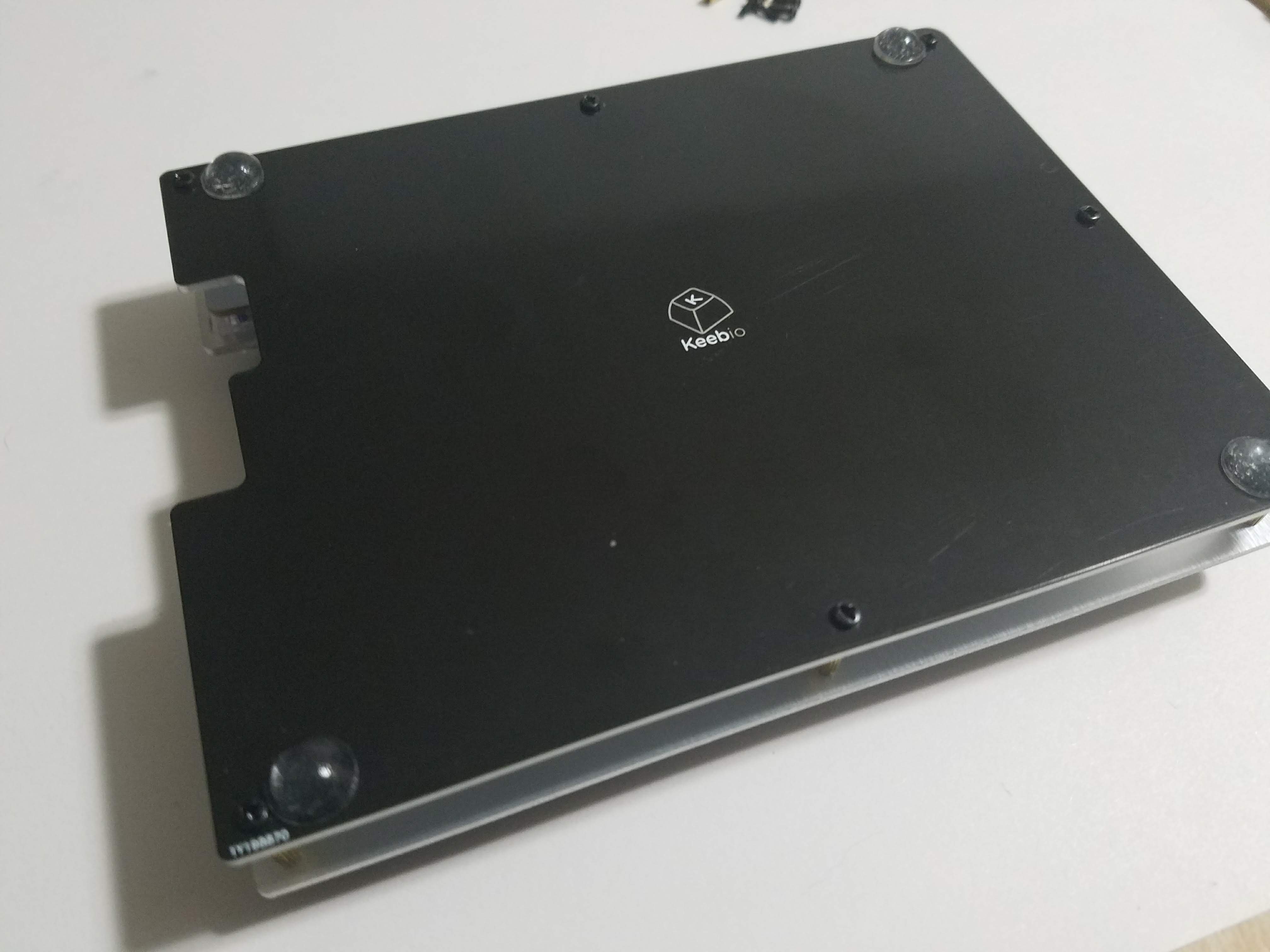
If you have some bumpons, stick one on each corner. Repeat on the other half and that's it!
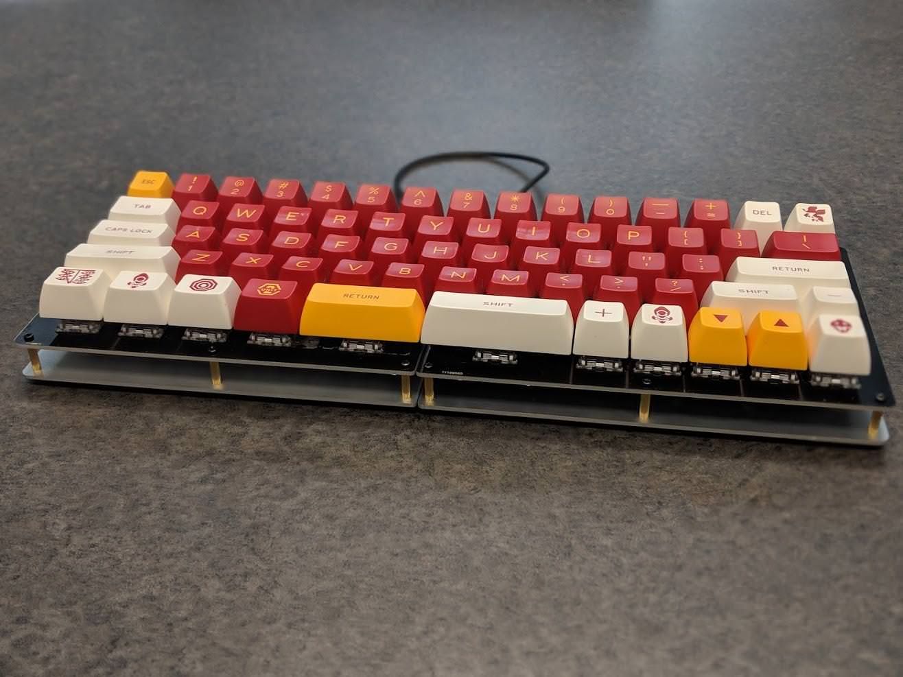
If you haven't yet, slap some caps on your new board. Now clack away!