Iris LM
Build Compatibility
This build guide is exclusively for the Iris LM, which supports Kailh Choc switches (V1 & V2) when using the Iris LM-K PCBs, or Gateron LP KS-33 switches when using the Iris LM-G PCBs.
Parts List
Get your parts ready:
- Iris LM PCB Kit
- Iris LM Case
- Aluminum version or Polycarbonate version
- 8mm M2 screws
- Silicone tray liners
- Switch plate support foam
- USB-C to USB-C cable
- 56 Low-Profile Switches
Build Steps Summary
- Inspect/Test Parts
- Add switches
- Assemble Case
- Board Notes
Inspect/Test Parts
Before starting assembly of the board, check if there's any issues with the parts in the keyboard kit.
For the 3D-printed version of the case, there is no foam support piece for the switch plate, as the printed switch plate has been made thicker to replace the foam piece.
There are also no o-rings for the case as well, since printing resolution is not high enough to print a spot to place an o-ring on.
The polycarbonate version of the Iris LM does not have o-rings, as there is no inset on the mounting points of the tray for o-rings to sit in.
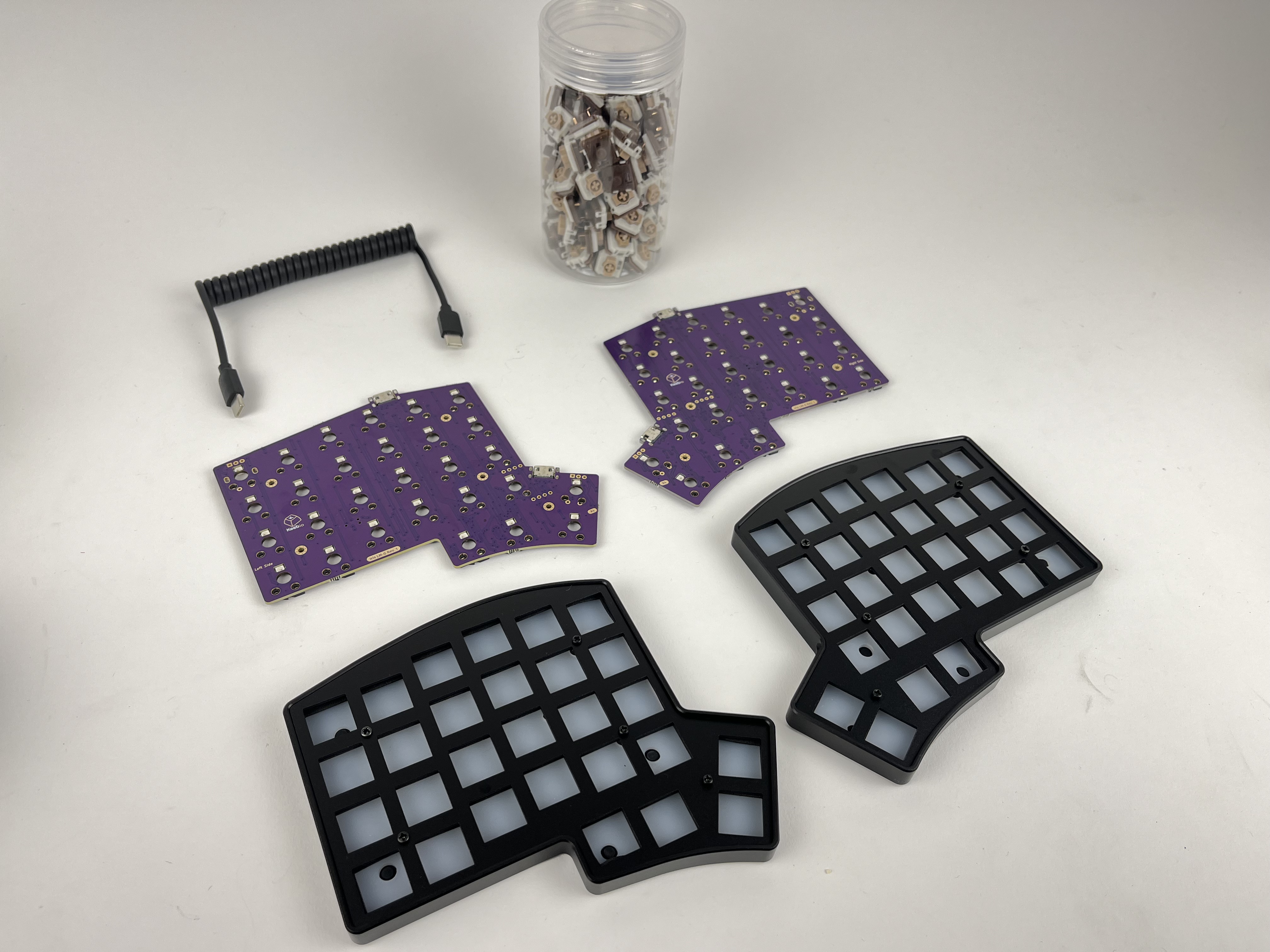
First, unscrew the switch plate from the tray, and remove the foam piece from the tray. You can leave the silicone liner in the tray.
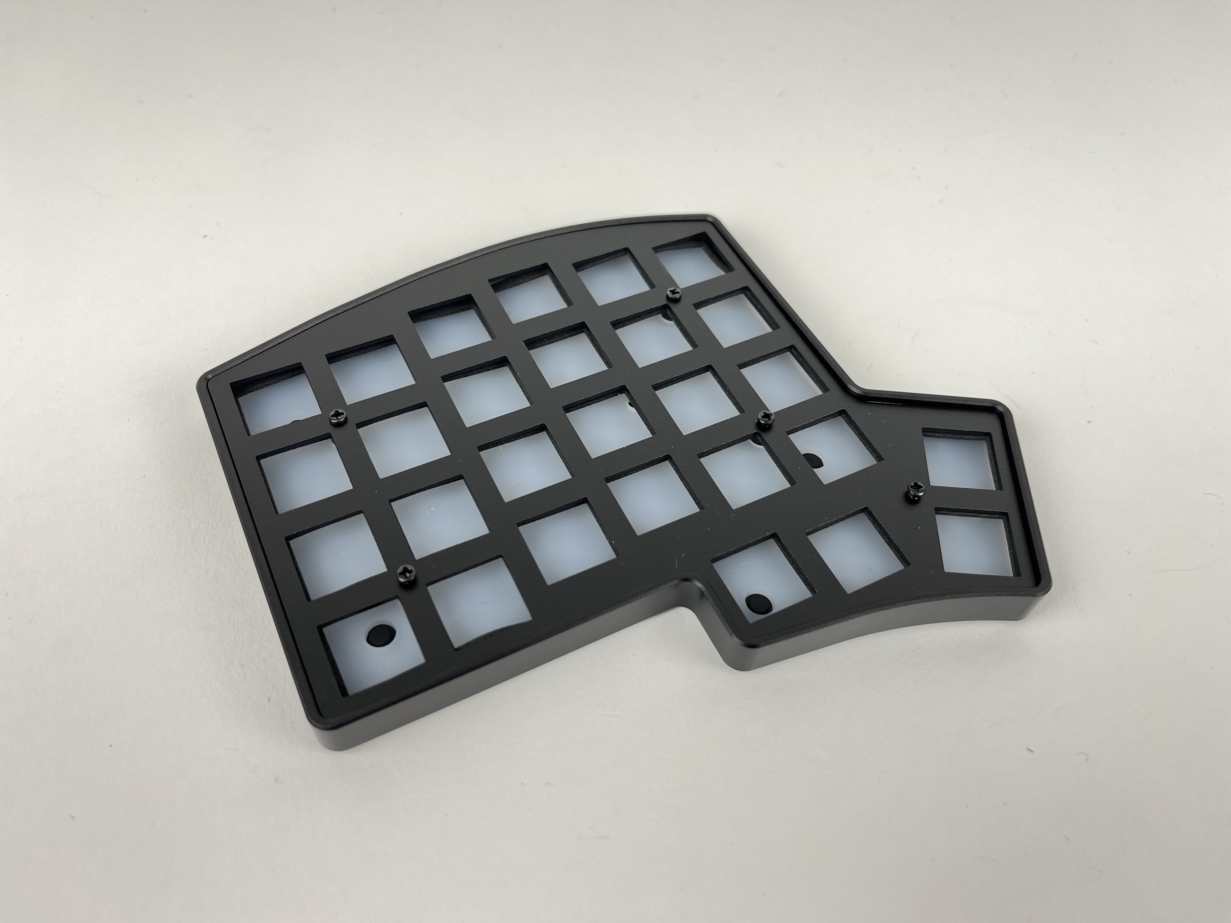
On top of each of the 5 mounting points on each half, there is a small, clear o-ring on it. Be careful not to lose these o-rings.
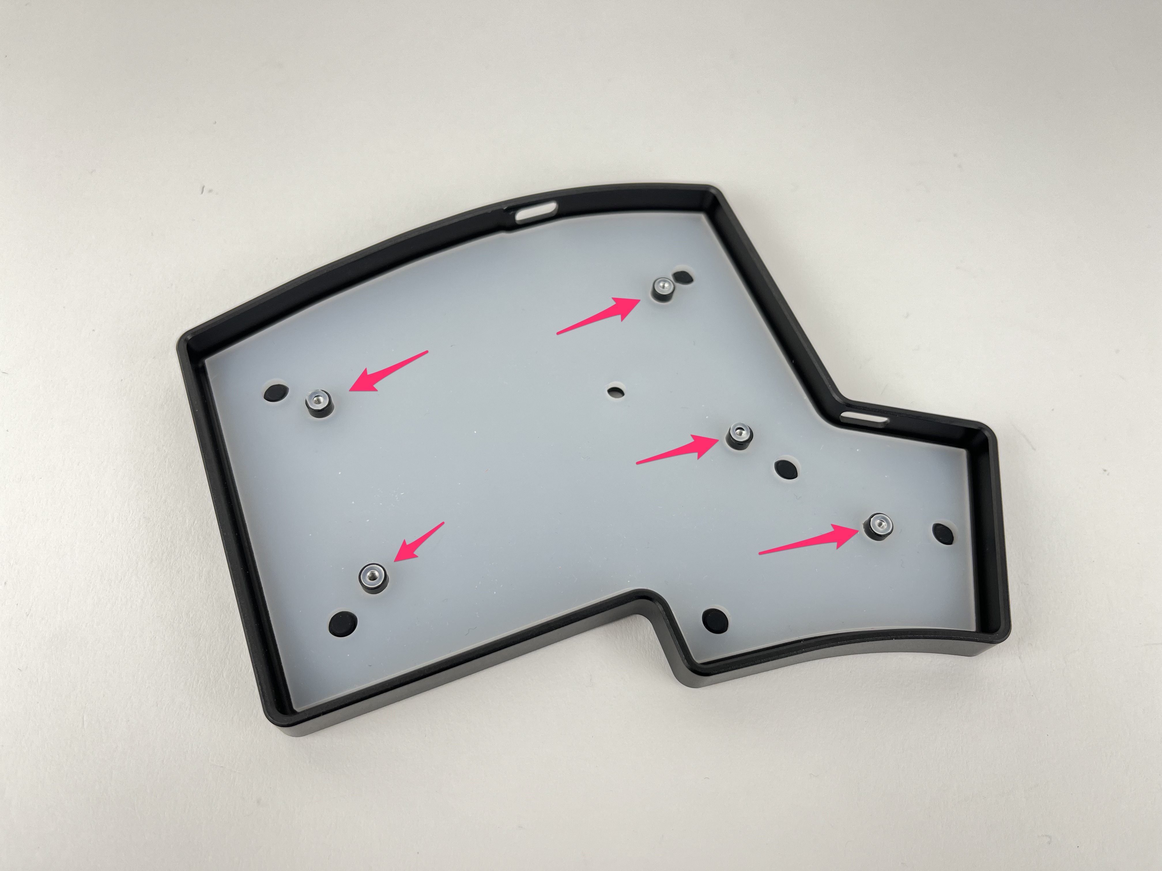
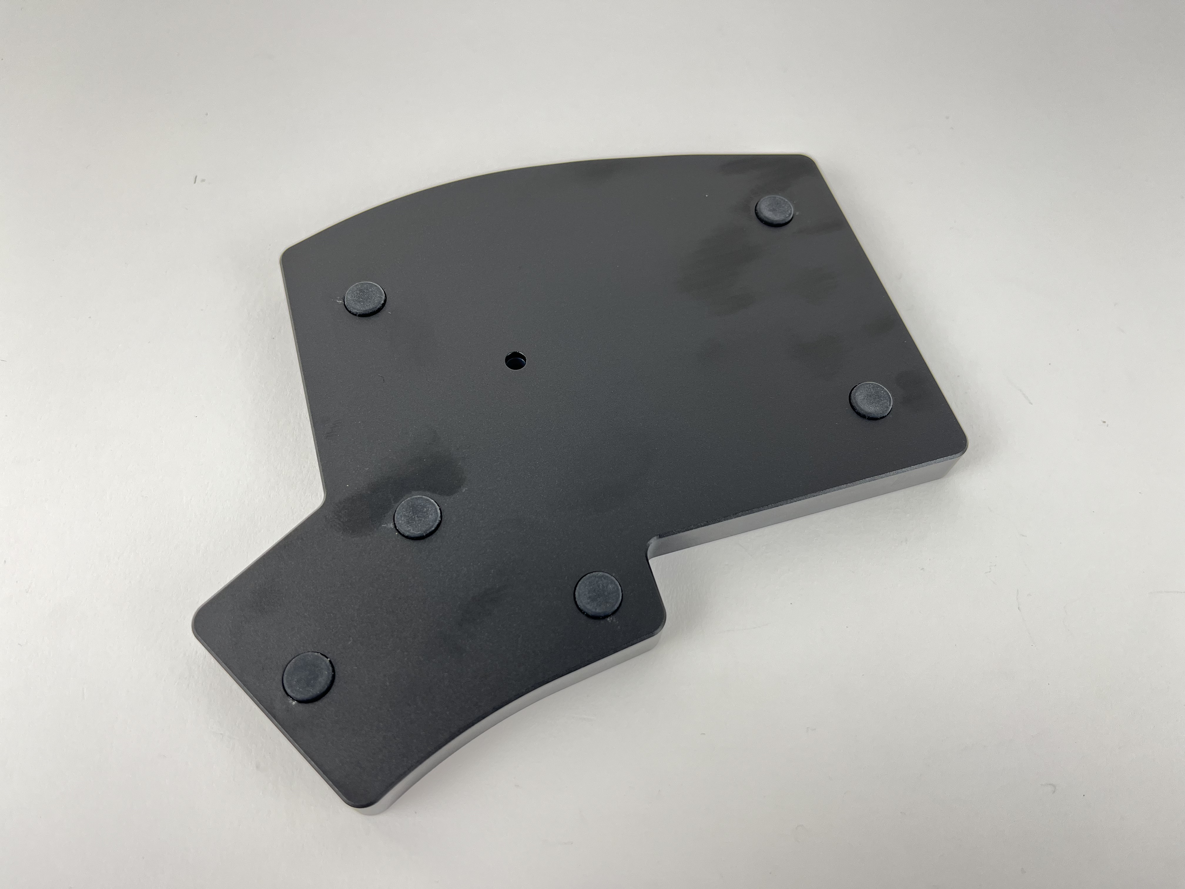
See if silicone bumpers are installed on the bottom of the case trays.
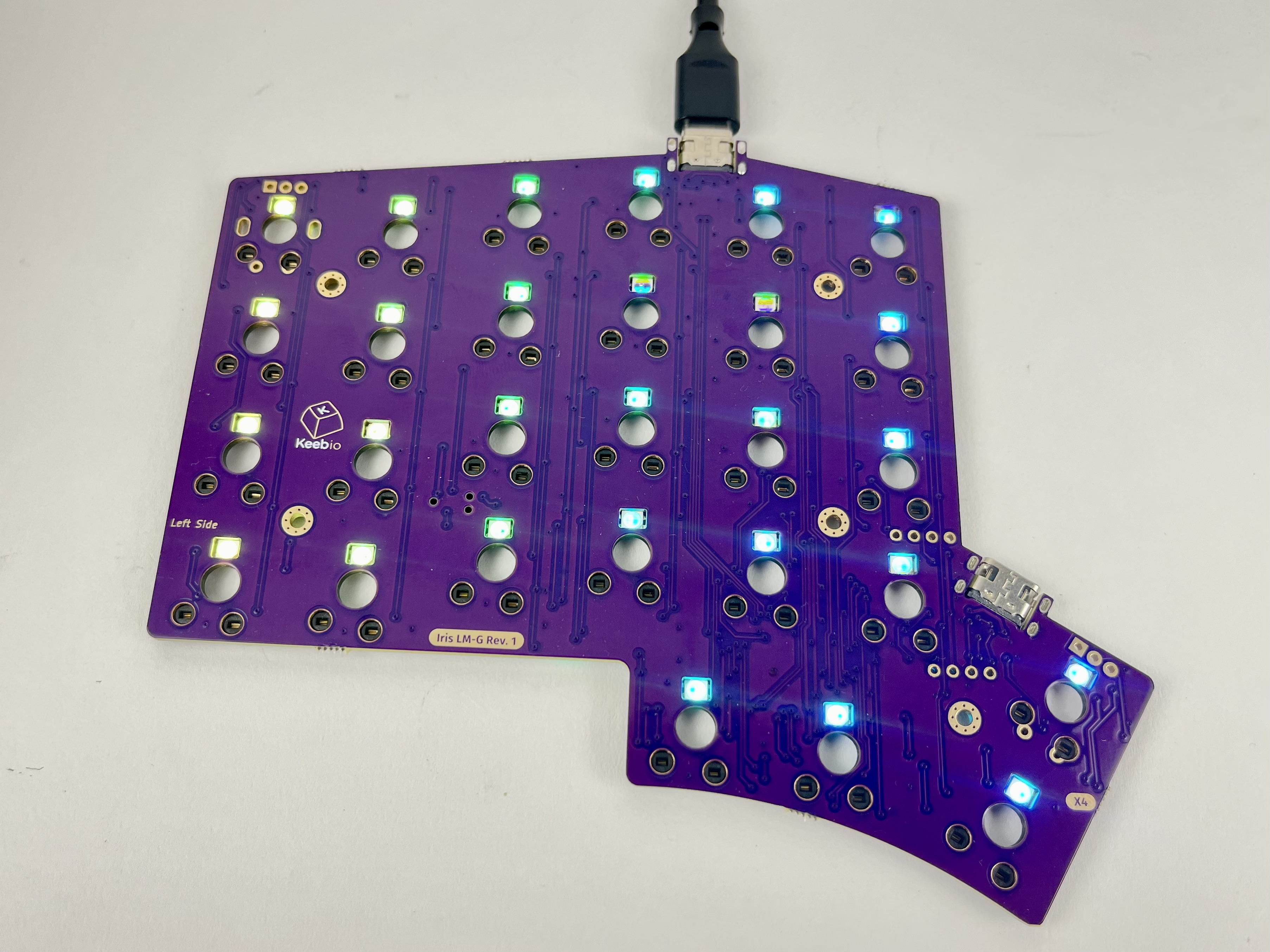
Plug in the PCBs and make sure all the LEDs are working.
Add switches
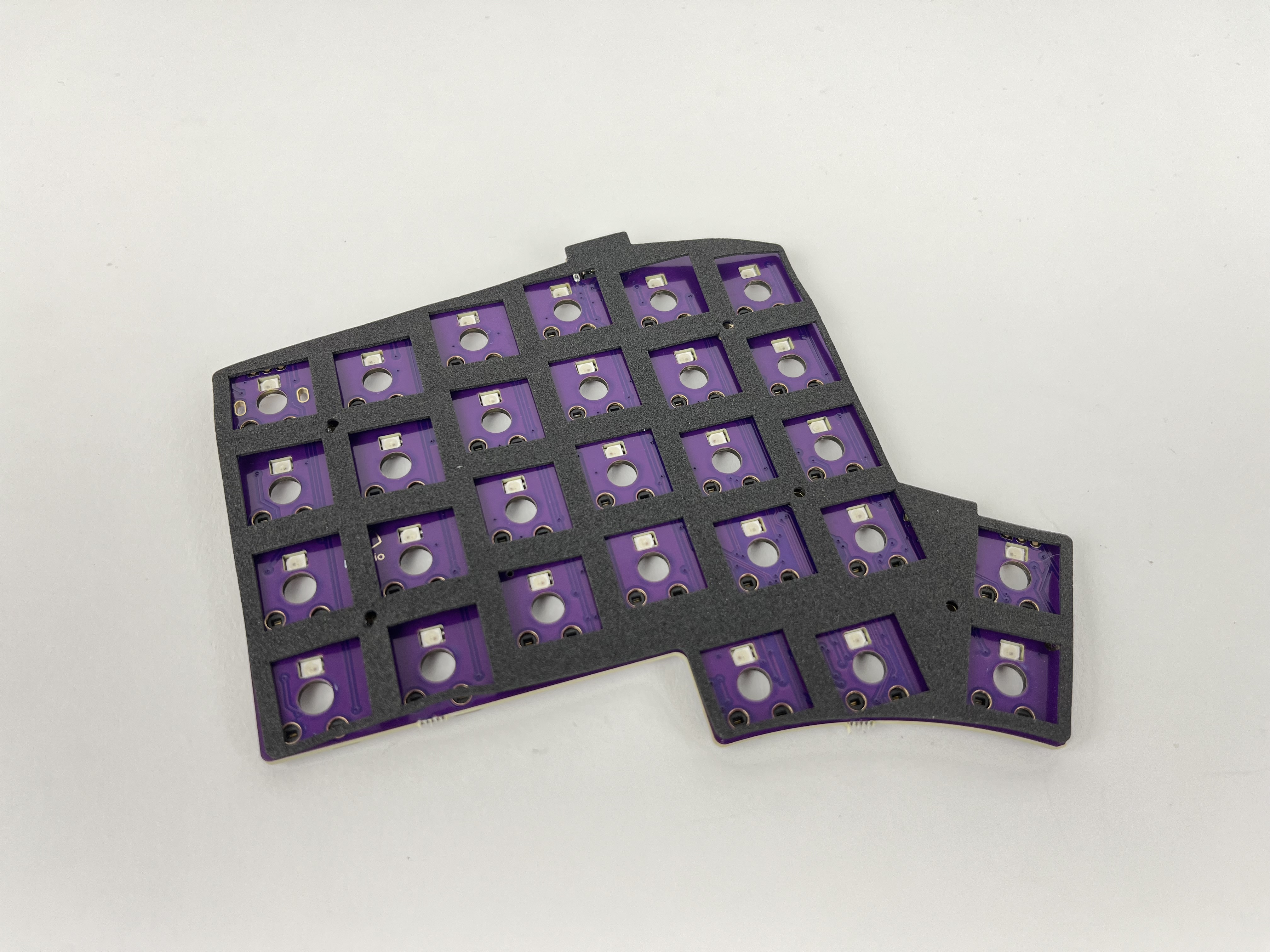
First overlay the foam piece over the PCB. Line up the screw holes with the holes in the piece.
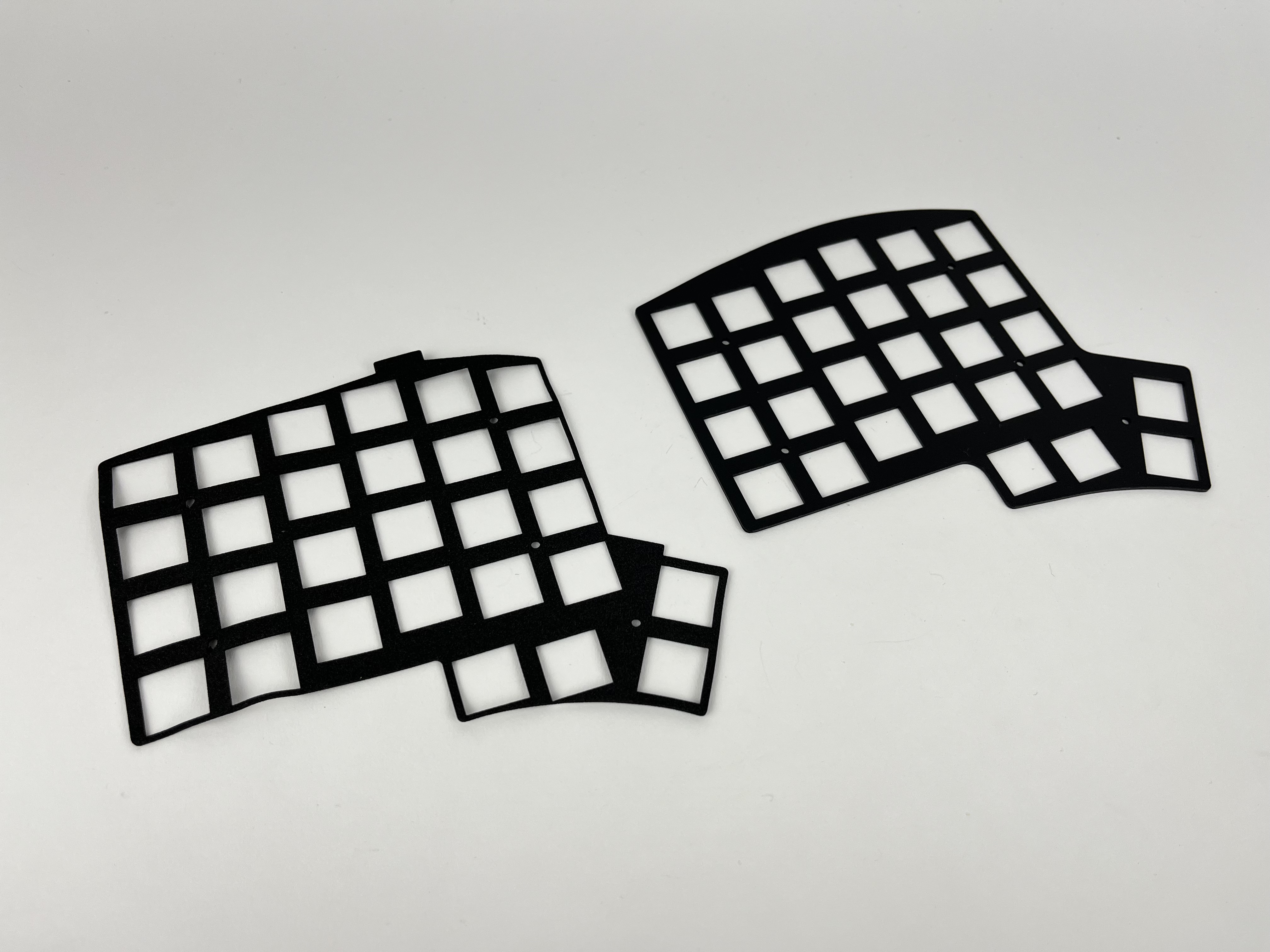
Add the switch plate on top of the foam piece, checking alignment of the screw holes again with the PCB.
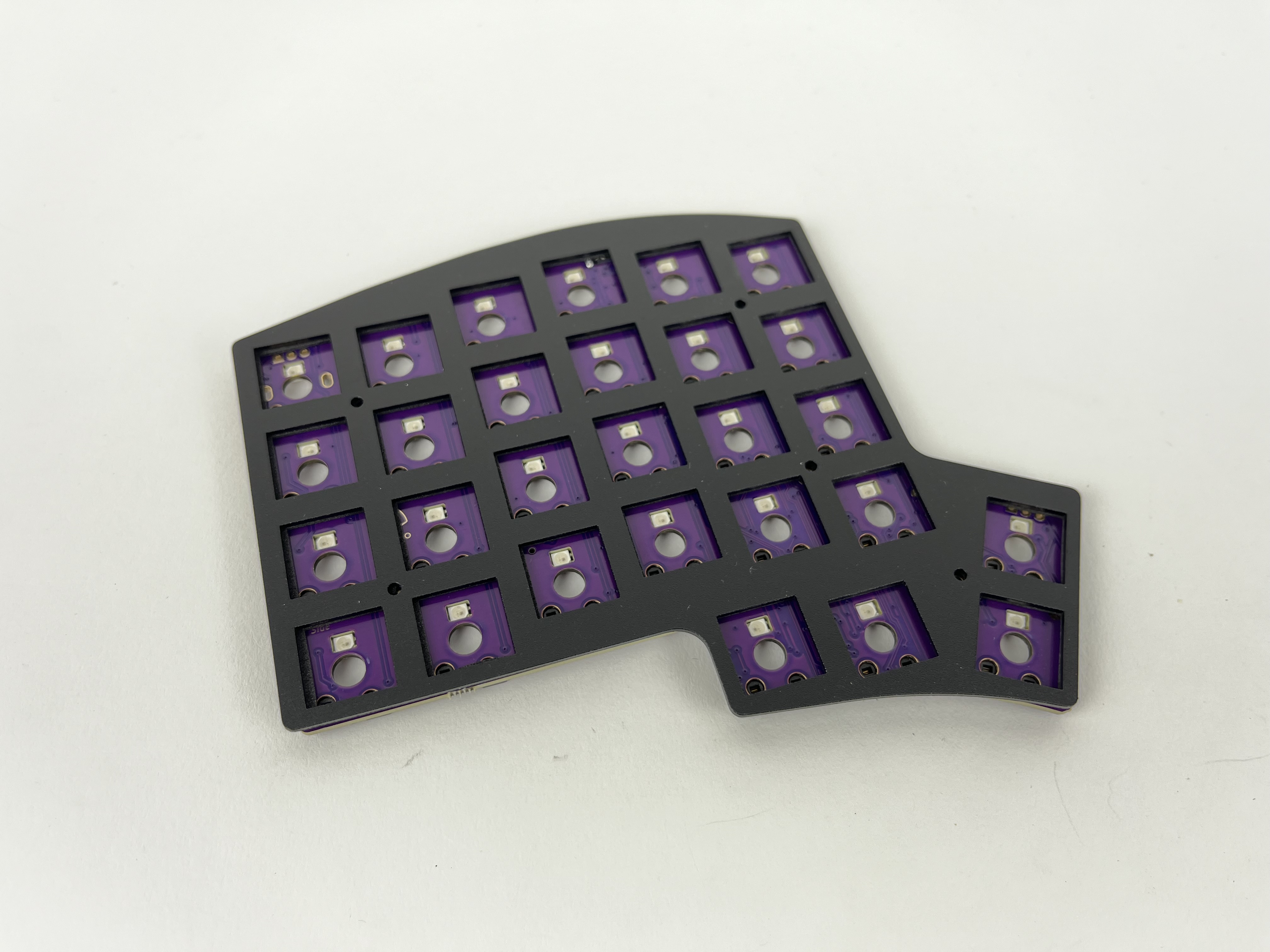
Insert a switch at one of the inner thumb keys and check that things are still lined up correctly.
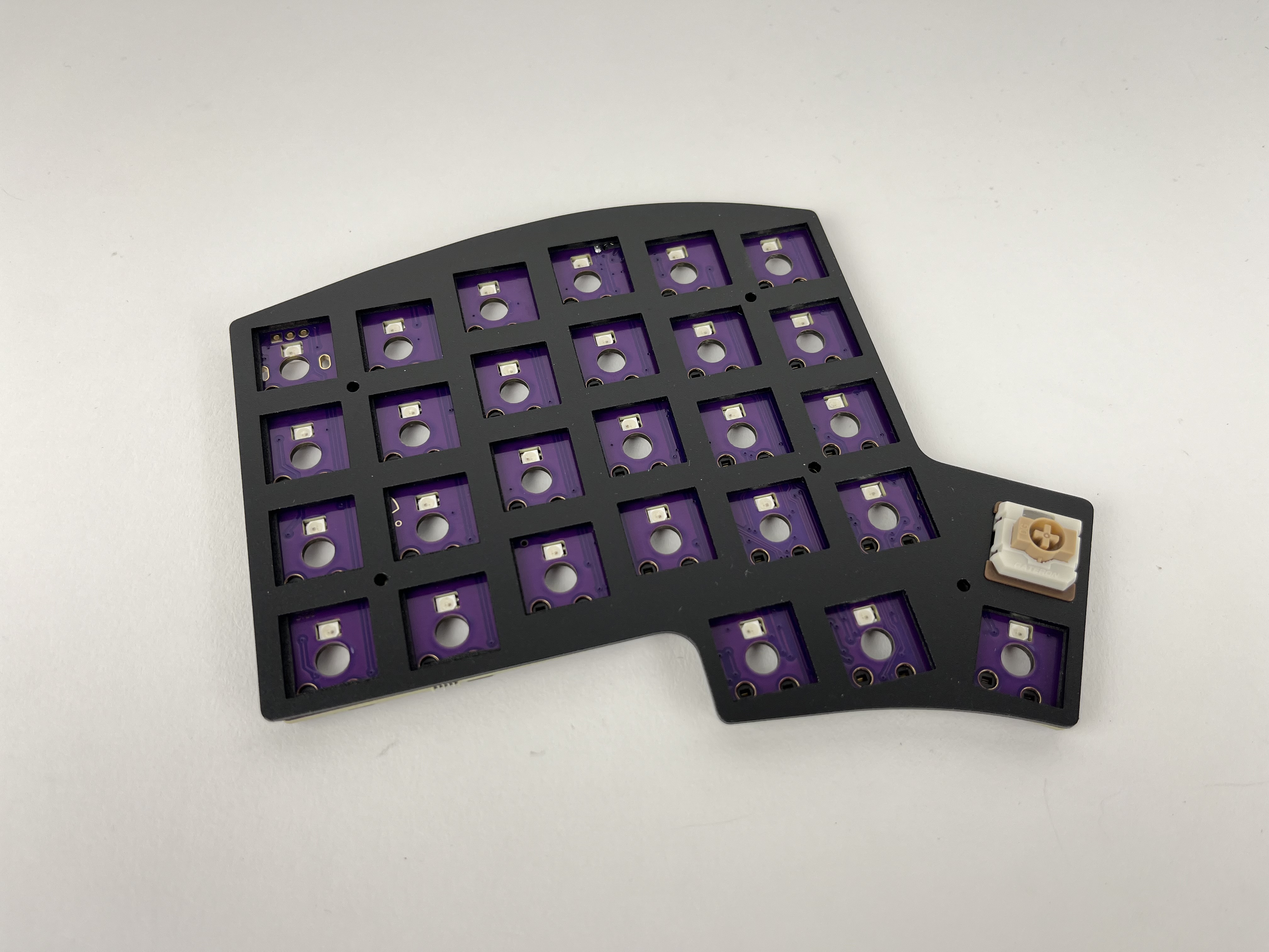
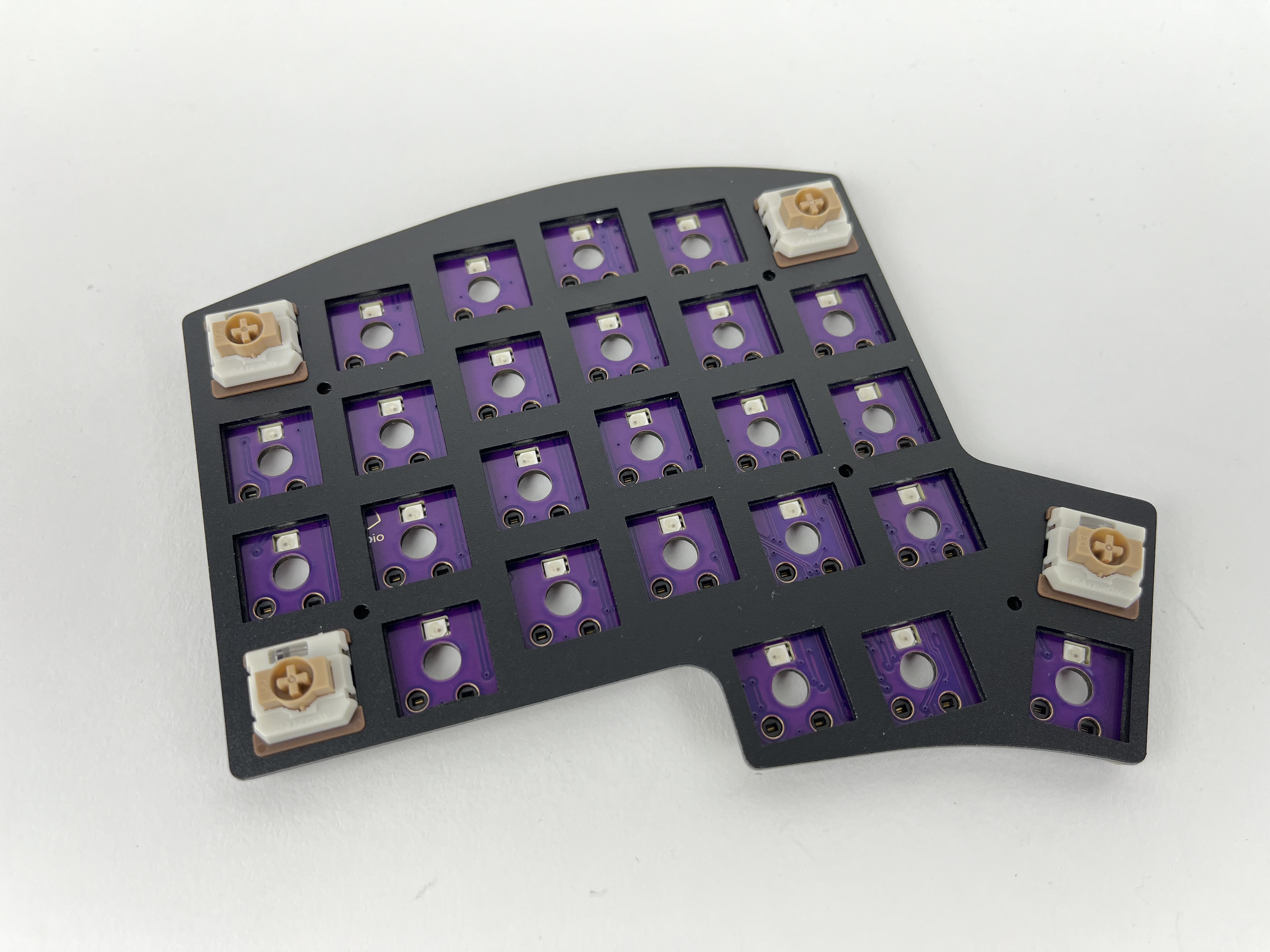
Insert some switches are the corners and check again that things are still lined up correctly. The switches should be flush with the plate. If a couple of the switches don't sit flat on the plate, remove the plate, reposition the foam piece, and try again.
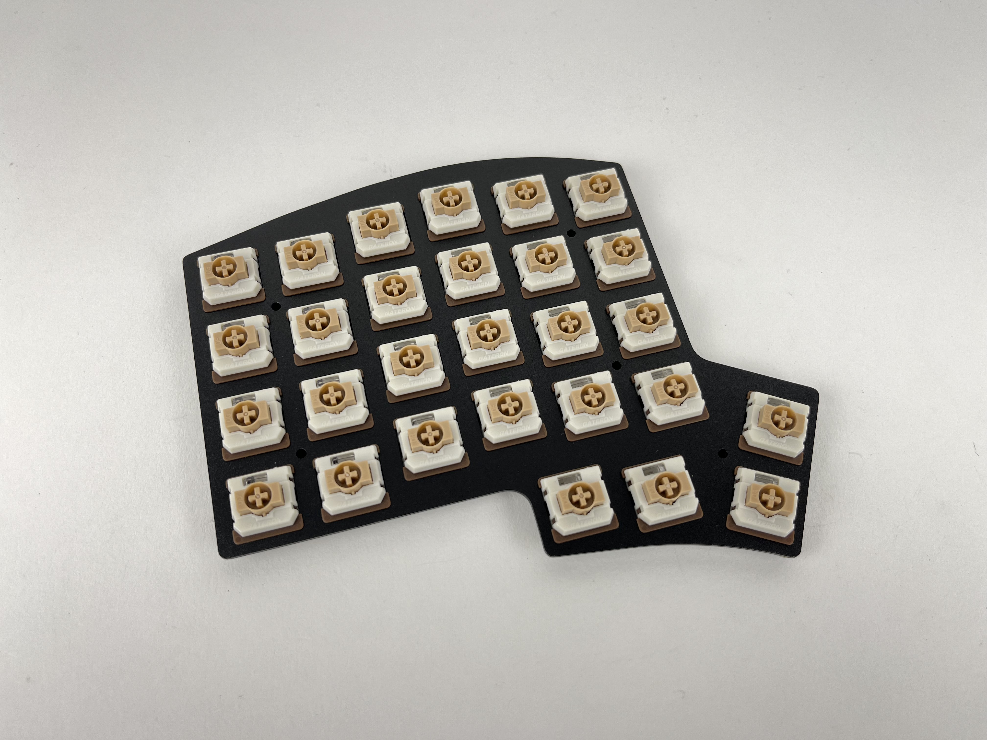
Add the rest of the switches.
Test keys
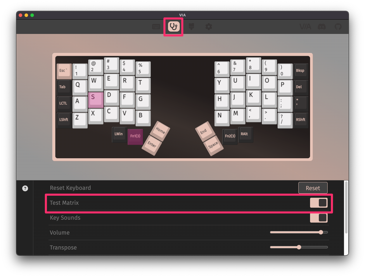
Before reassembling the case, plug the USB cable into the PCB and test all of the keys to make sure everything is working, as it'll be easier to fix switch issues now than later.
It's best to test using the Key Tester in VIA with Test Matrix mode on, as this will let you test the Lower and Raise keys properly.
Assemble Case
Now that all of the switches have been inserted, it's time to assemble the case.
(Optional) Place an o-ring over each of the mounting points. This will provide some cushion between the top portion of the build from the tray bottom of the case.
Next, place the plate assembly into the tray.
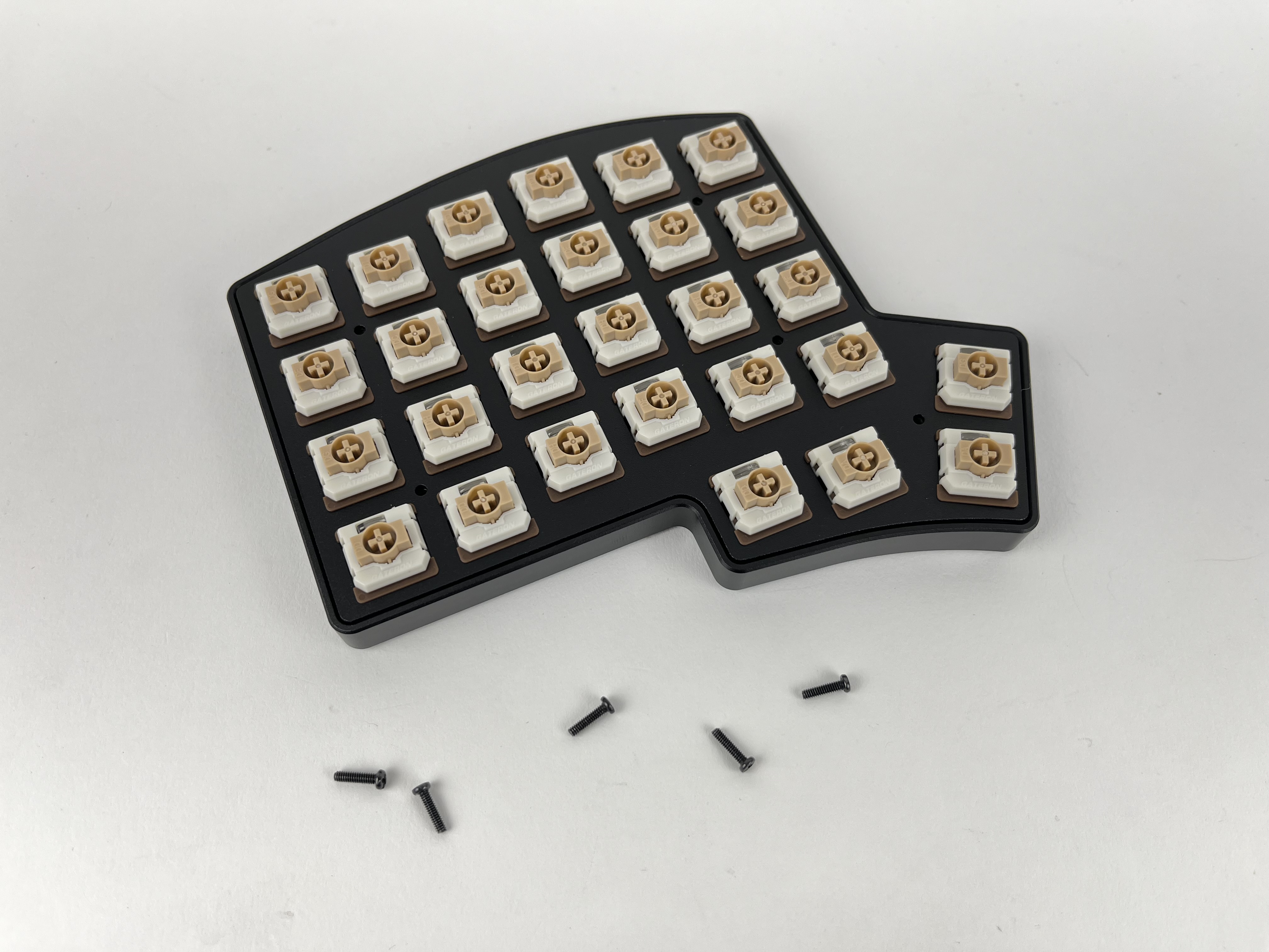
Add screws to each of the holes and screw them in. You do not need to overly tighten them. Doing so on the polycarbonate version of the case will damage the bottom of the case.
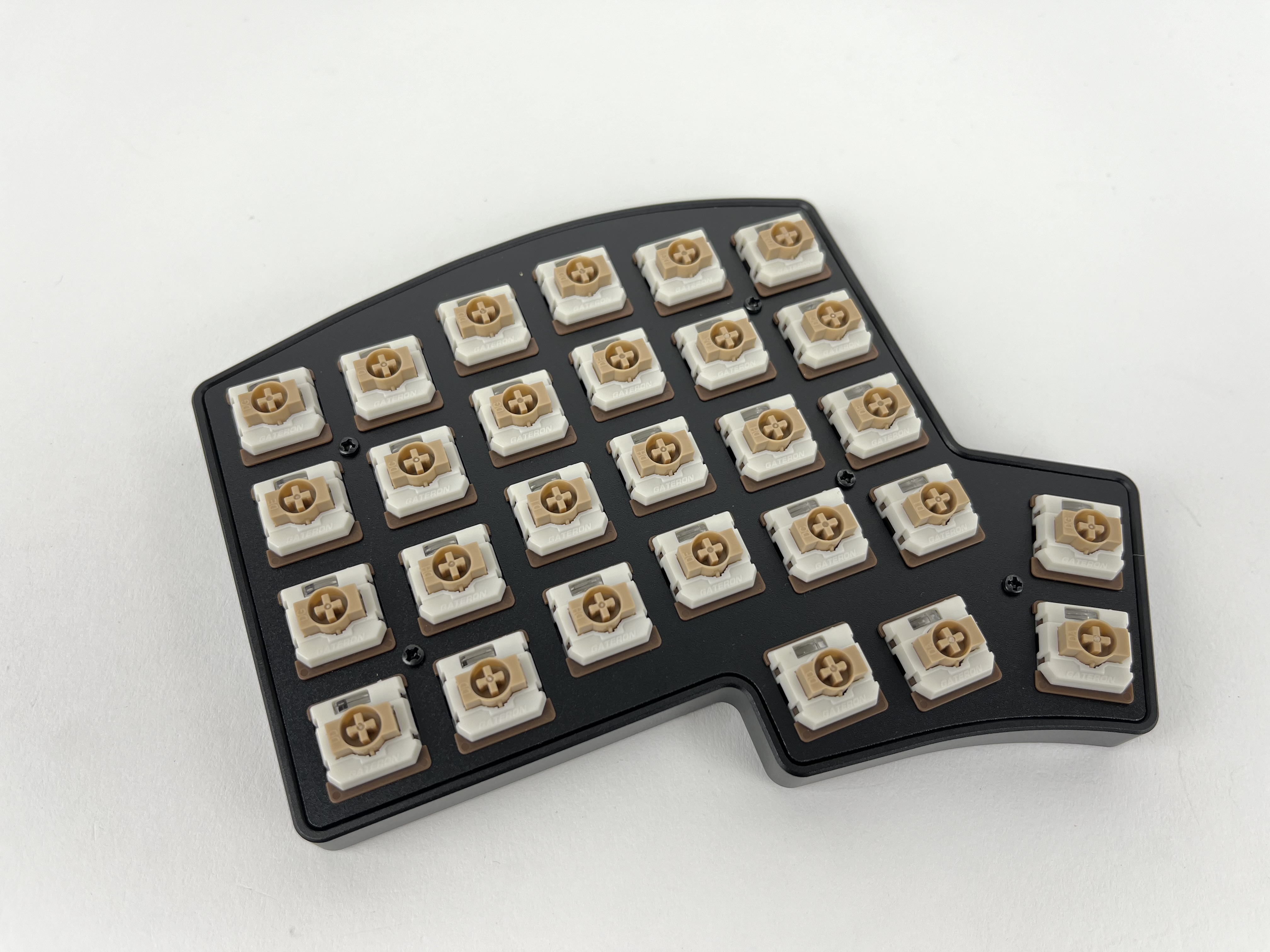
Add keycaps to all of the switches.
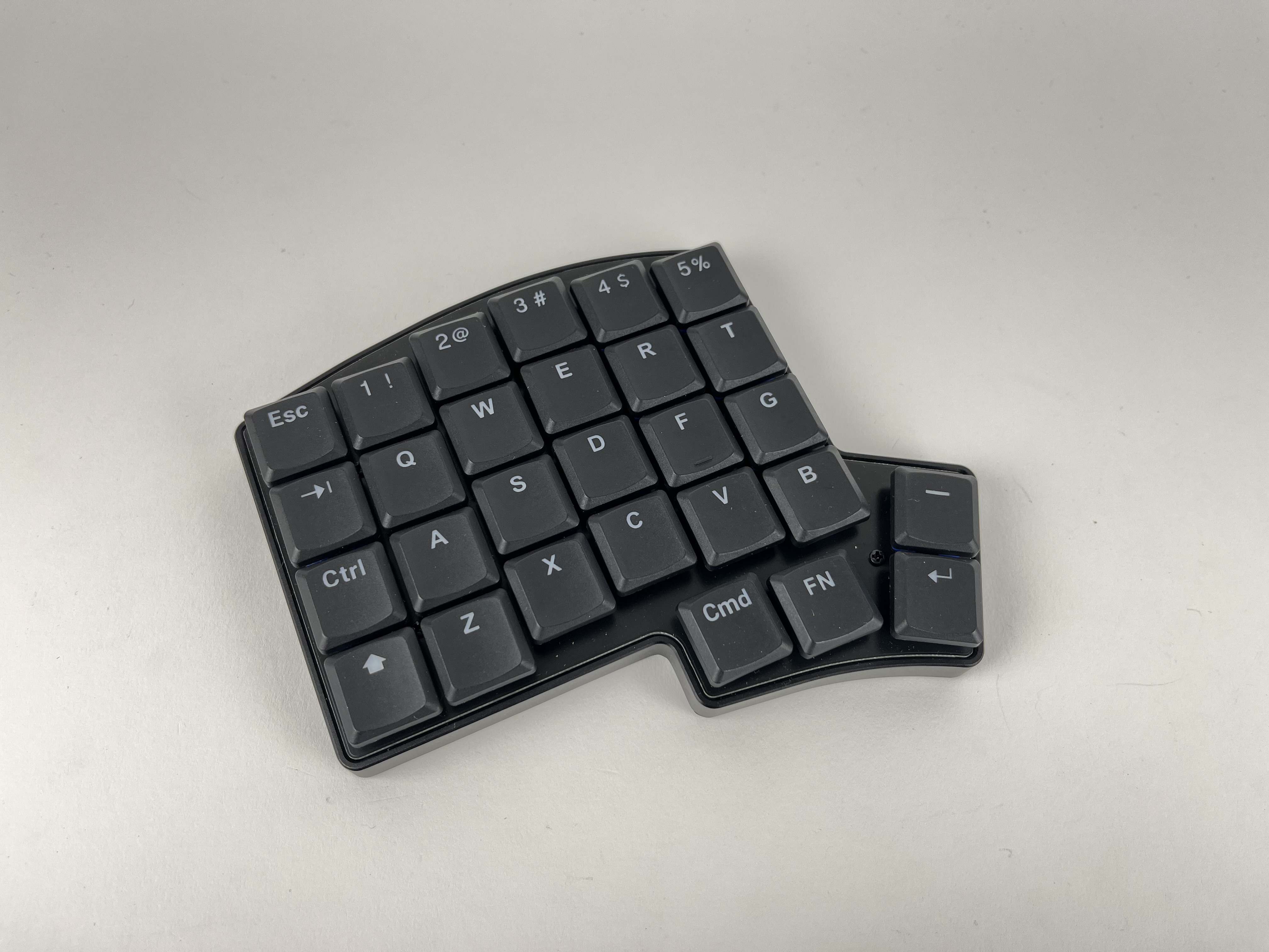
Repeat the same process for the other half of the keyboard.
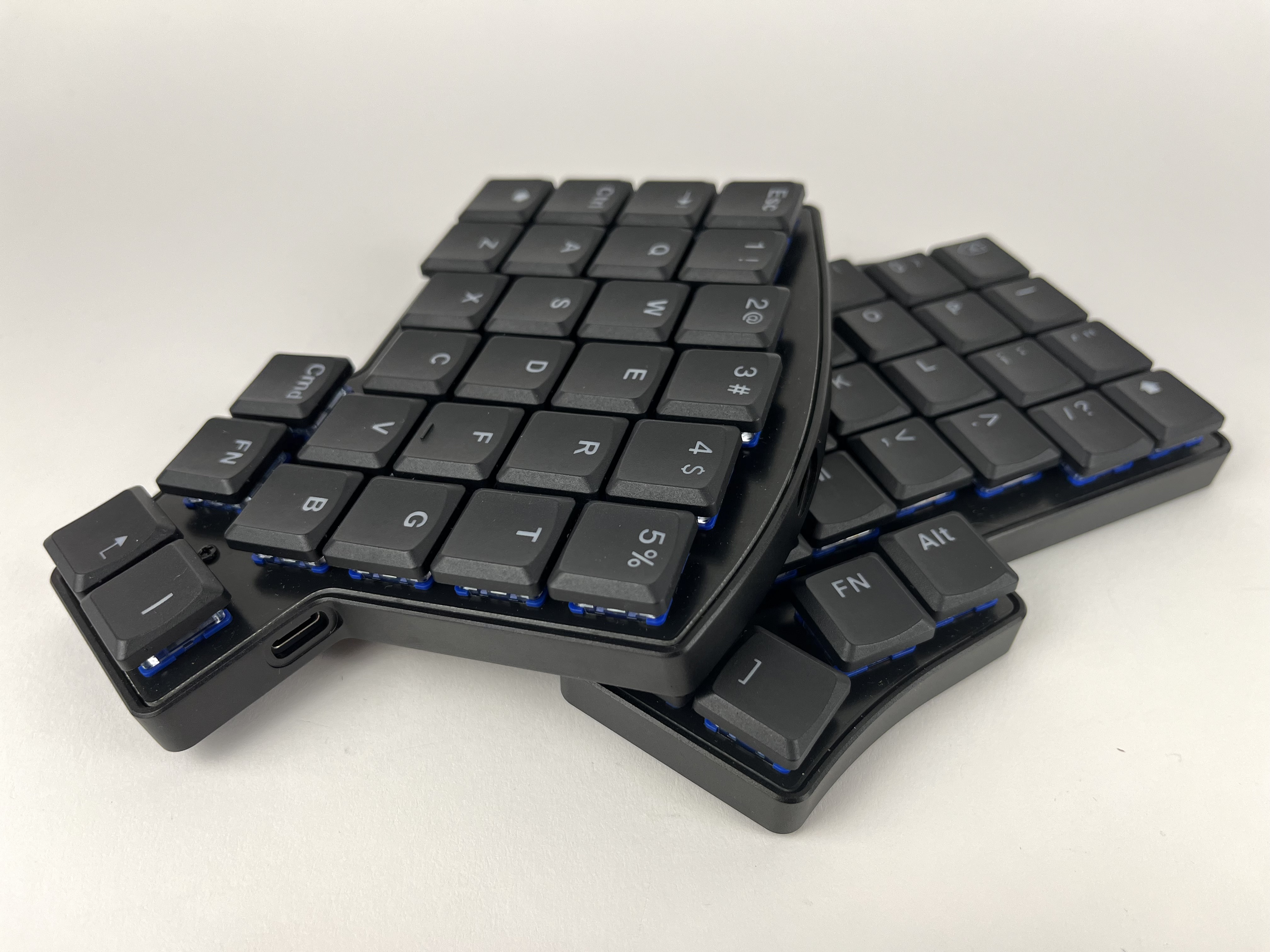
Default Keymap
Here's the default keymap if you need it: Iris Default Keymap
Remapping/reprogramming Board
Looking to remap/reprogram your board? Check out our guide for remapping your keyboard.
While the bottom plates have a hole at the bottom to allow you to access the reset button to allow your Iris to be reflashed if you are using QMK, if you don't want to be flipping your board over to press reset, you can also use one of the following options when remapping your Iris:
- Use VIA to remap your keys. The stock firmware on the Iris LM already has VIA support enabled. This allows you to remap the keyboard without having to reflash the board.
- If you are not using VIA and are using QMK instead, use the
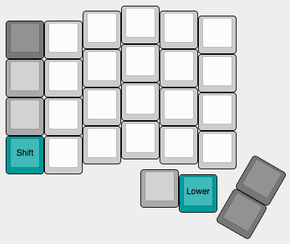
QK_BOOTkeycode to reset the keyboard to allow it to be reflashed without needing to physically press the reset button on the PCB. The default way of usingQK_BOOTis by pressingLower+Ron the left half orRaise+Delon the right half as shown below:
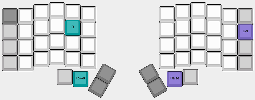
For reference, the Iris LM PCB uses a STM32G431 microcontroller.
Turning off RGB LEDs
If you'd like to turn the RGB LEDs off, you can control the RGB settings in VIA.
If you still have the default keymapping, you can also hold the Lower key and then press Left Shift as highlighted below: