Breeze Rev. 1.4 Build Guide
- MX Version
- Choc Version
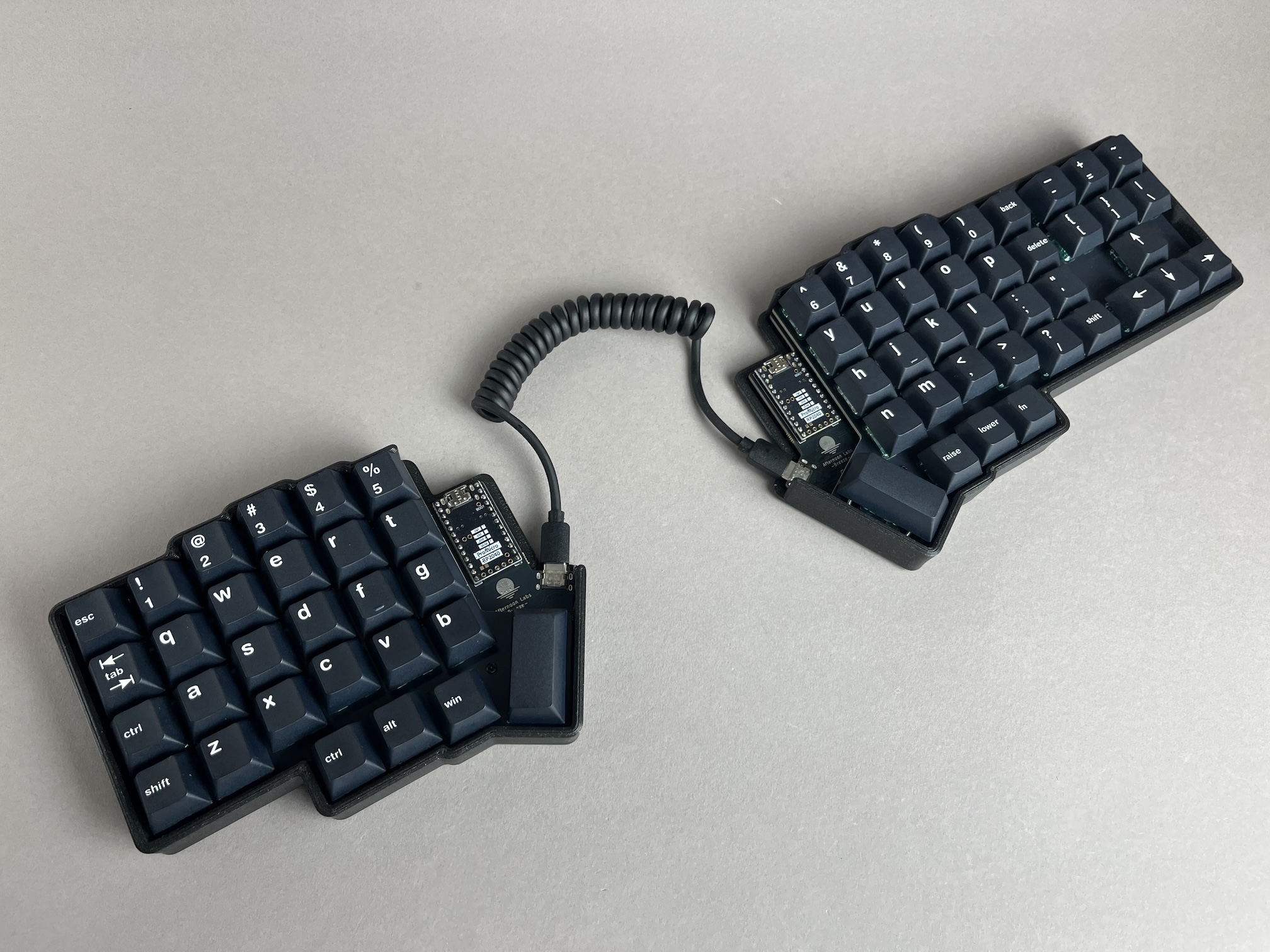
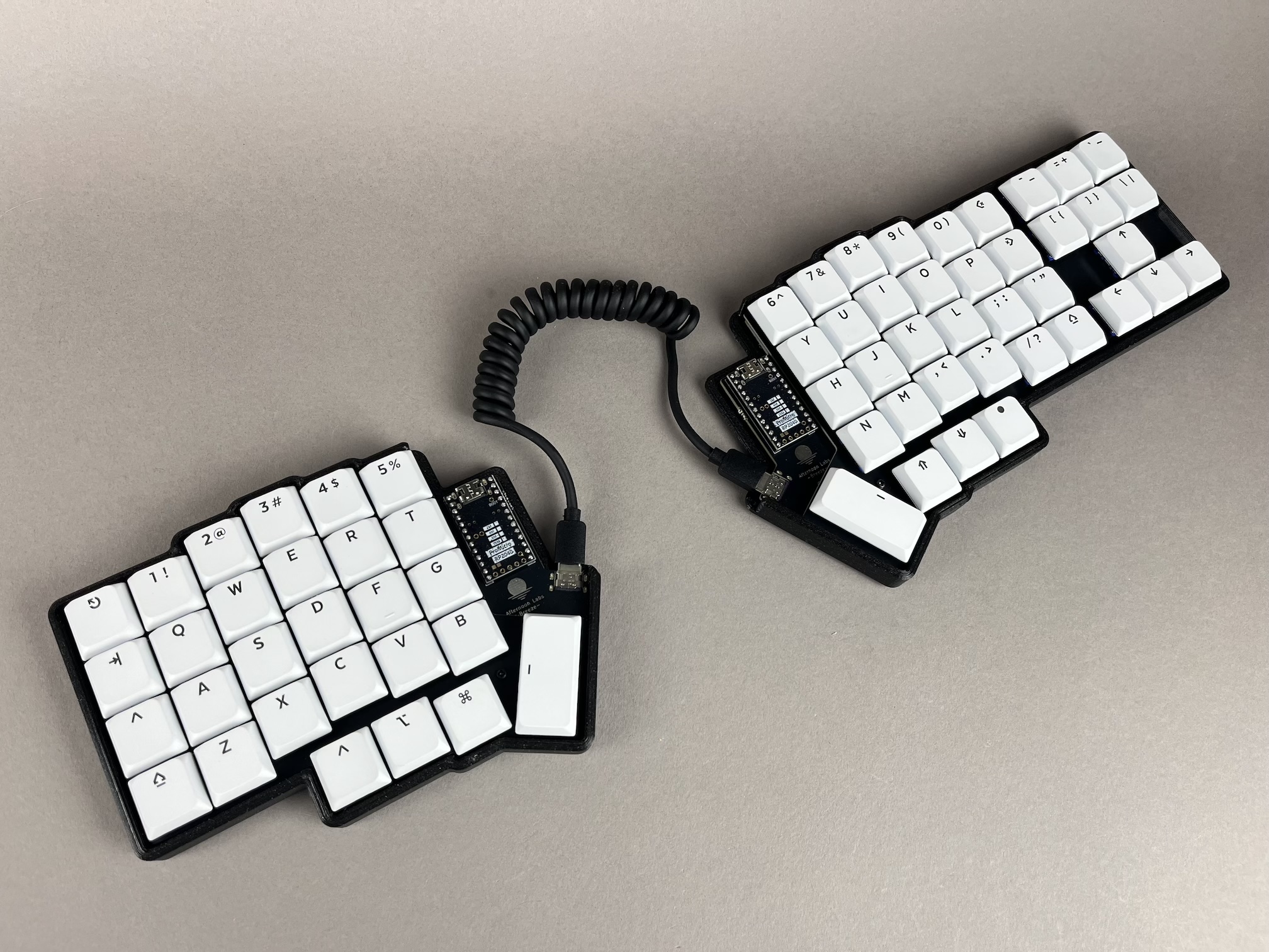
The Afternoon Labs Breeze Rev. 1.4 is a version of the Breeze that has some modifications made to it (like replacing TRRS with USB-C), and all the needed components except for the microcontrollers are pre-soldered on the boards.
In comparison to the Rev. 1.3, the Rev. 1.4 adds pads, Pico-EZmate connector, and power switch for adding batteries, and it also has a slightly more compact shape for a sleeker look.
Build Compatibility
This build guide is specifically for the Breeze Rev. 1.4 sold by Keebio, which comes in a kit with PCB and case.
Parts List
First up, time to get your parts:
- MX Version
- Choc Version
- Breeze Kit which includes:
- Breeze Rev. 1.4 PCBs with Kailh MX hotswap sockets
- FR4 Switch Plates
- 11 10mm M2 Screws
- Shroomie Feet
- USB-C to USB-C cable
- 2x 2u PCB mount MX stabilizers
- 70 MX-compatbile Switches
- MX-compatible Keycaps
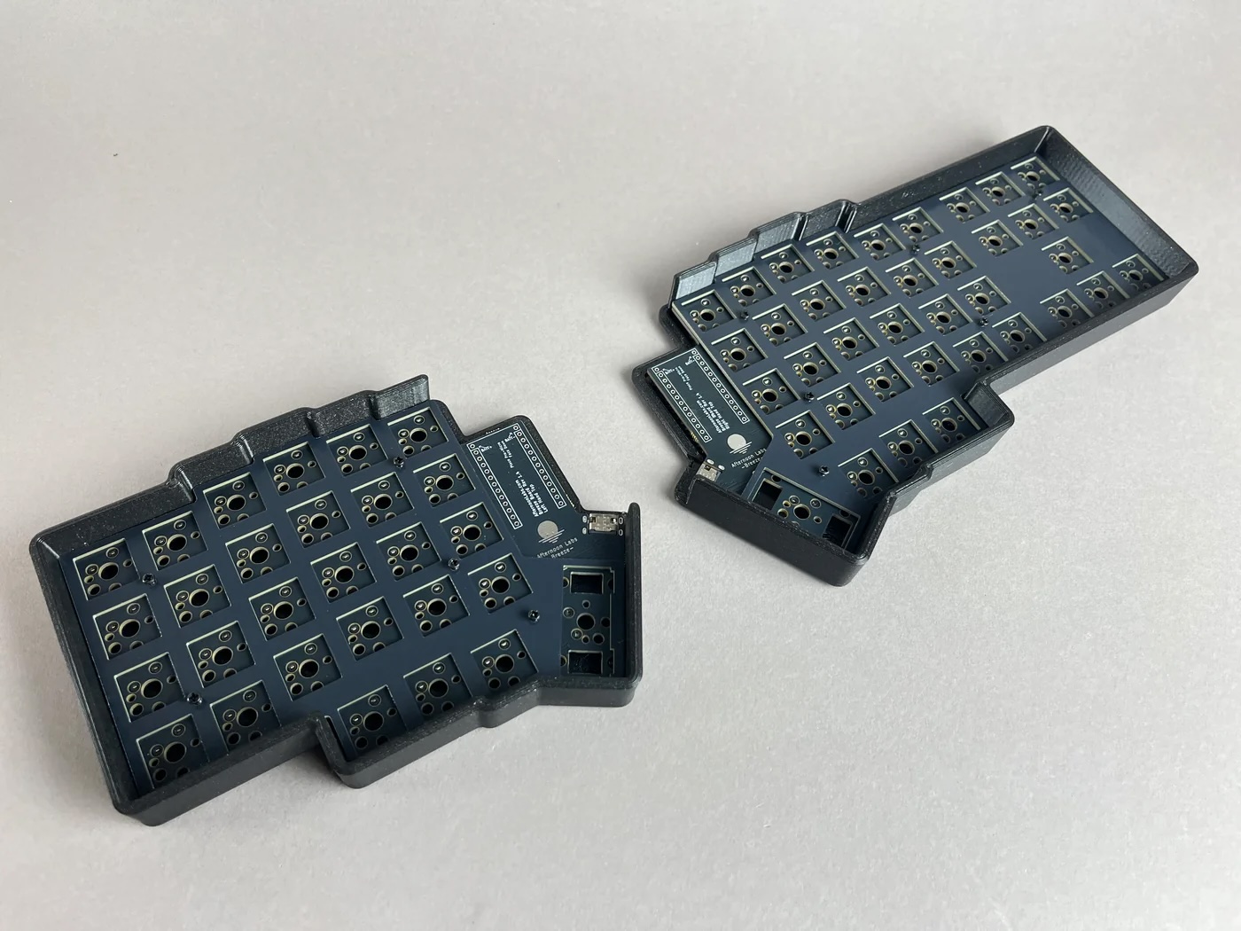
- Breeze Kit which includes:
- Breeze Rev. 1.4 PCBs with Kailh Choc hotswap sockets
- FR4 Switch Plates
- 11 6mm M2 Screws
- Shroomie Feet
- Choc V2 Stabilizers
- USB-C to USB-C cable
- For Choc V1 Builds:
- For Choc V2 Builds:
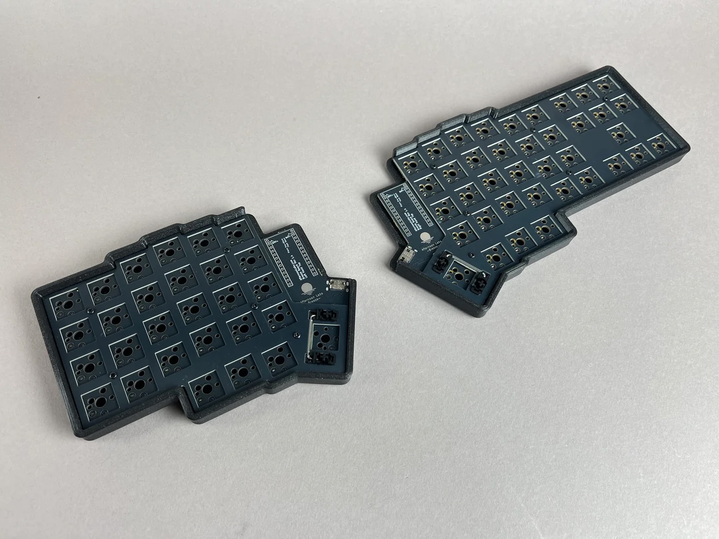
Build Steps Summary
- Disassemble Case
- Flash Microcontrollers
- Solder Microcontrollers
- Add Stabilizers
- Add Switches
- Assemble Case
- Add Keycaps
- Board Notes
Disassemble Case
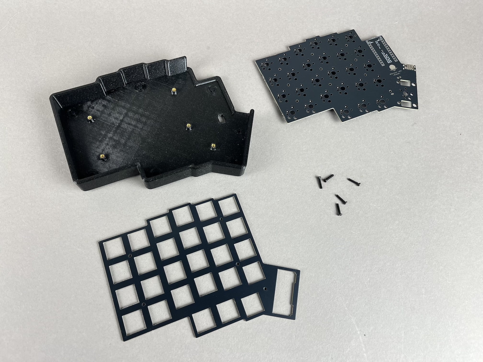
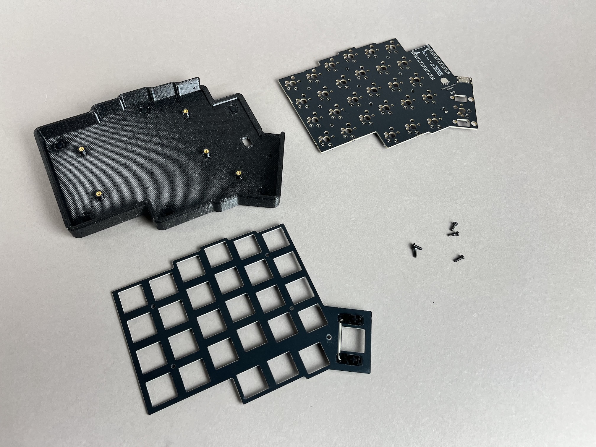
The first thing to do is unscrew the screws from the case.
- MX Version
- Choc Version
Flash Microcontrollers
Flash the firmware to the microcontrollers first before soldering them to the PCB, as removing the controllers from the PCB is difficult if you have any problems with it and need to desolder them. The Boot button on some controllers are also difficult to access when soldered to the PCBs, so that's another reason to flash and test them upfront.
Here's the firmware for the Breeze with support for VIA enabled for different microcontrollers:
- Wired Build
- Wireless Build
- Breeze Firmware for SuperMini nRF52840 Pro Micro - To be built
See Flashing Firmware for more info on flashing your controllers.
Solder Microcontrollers
Place both of the PCBs face up and insert the header pins into the holes for them.
If your controller has 2 columns of 12 pins instead of 13 pins, insert the header pins into the lower 12 pins, as the top 2 pins are for battery usage.
12 pin columns
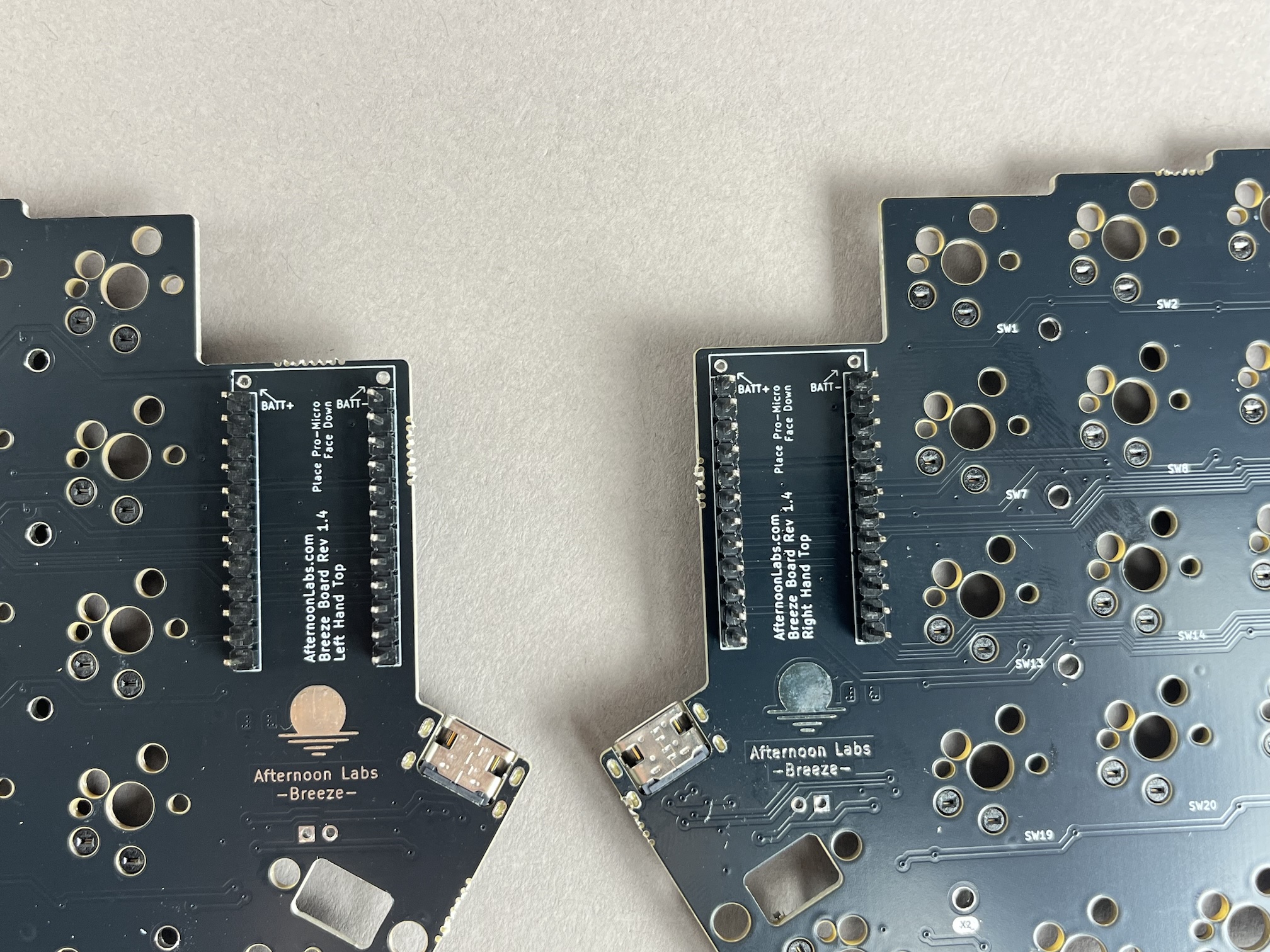
13 pin columns
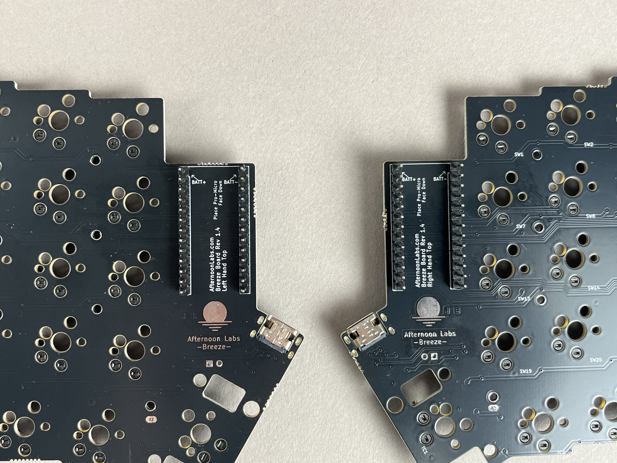
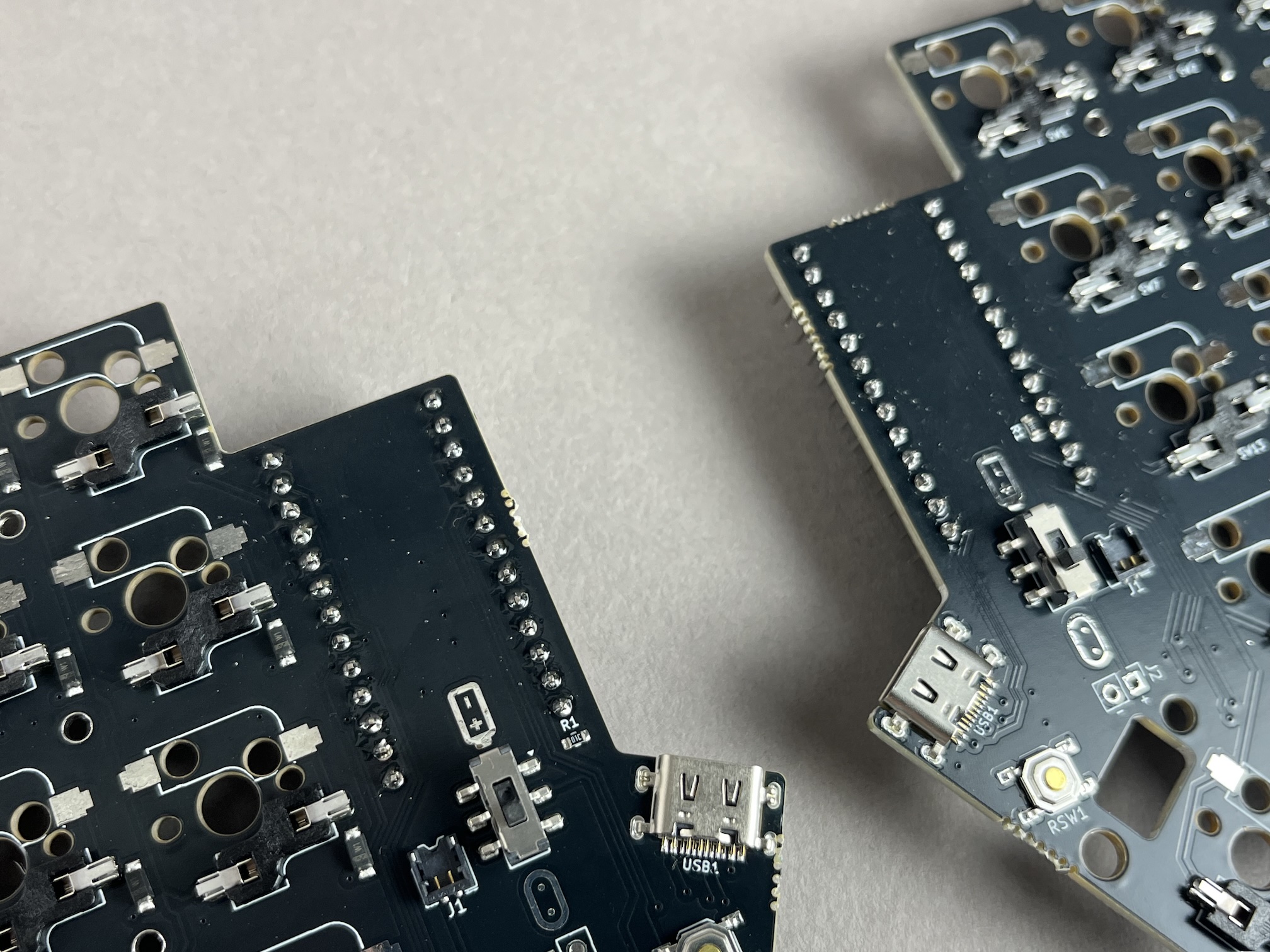
Flip the PCBs over and solder the header pins.
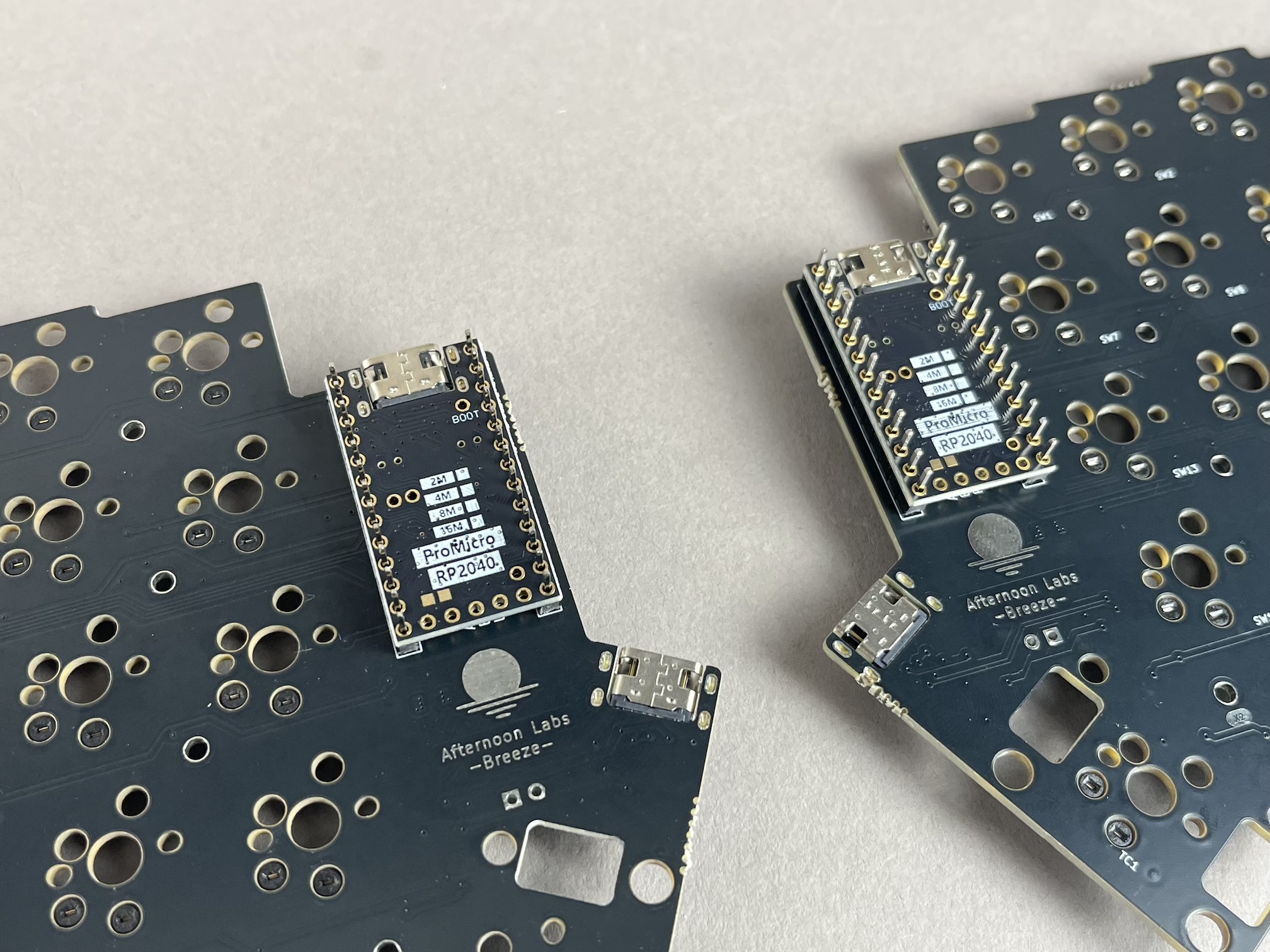
Flip the PCBs back over and put the controllers over the header pins. The chip side of the controller should be facing down.
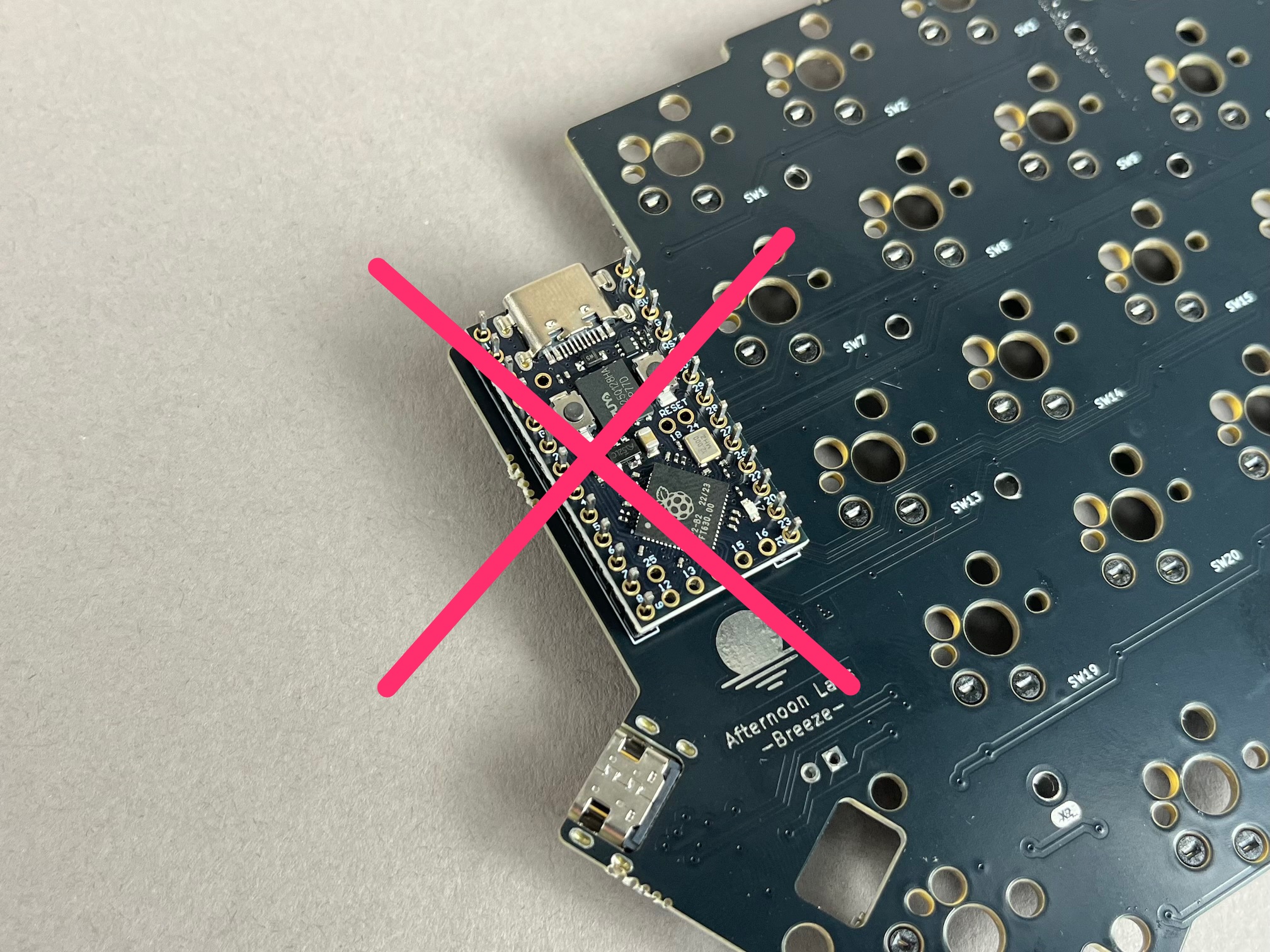
Don't insert the microcontroller with the chip side face up, it won't work properly that way.
Solder the controllers to the header pins.
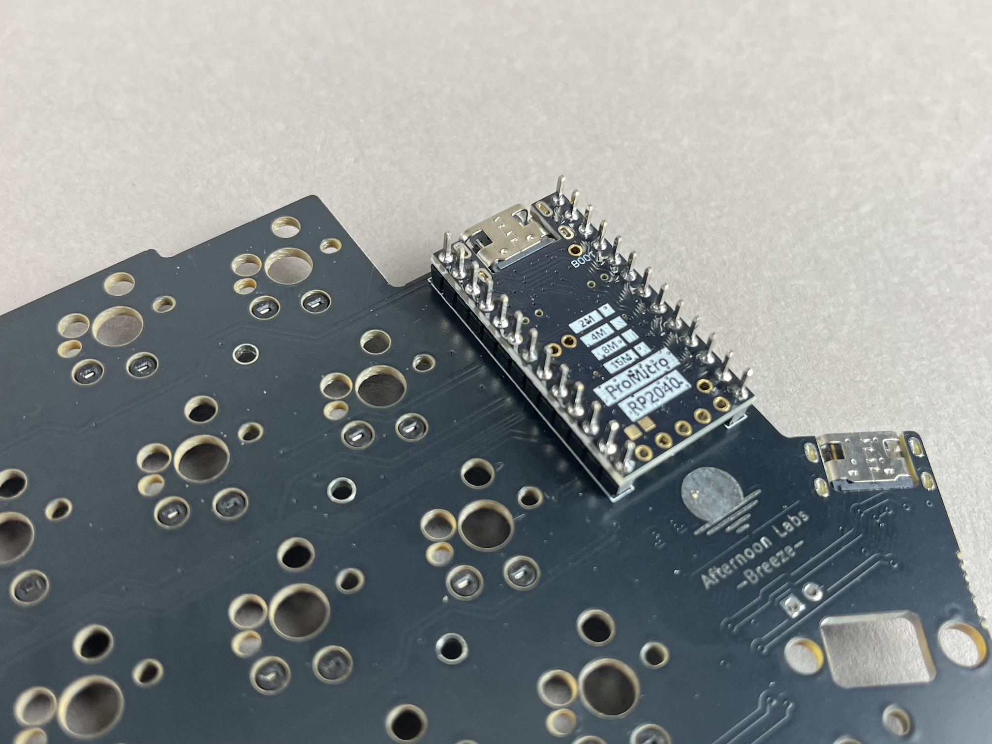
Then clip the extra length of the header pins off.
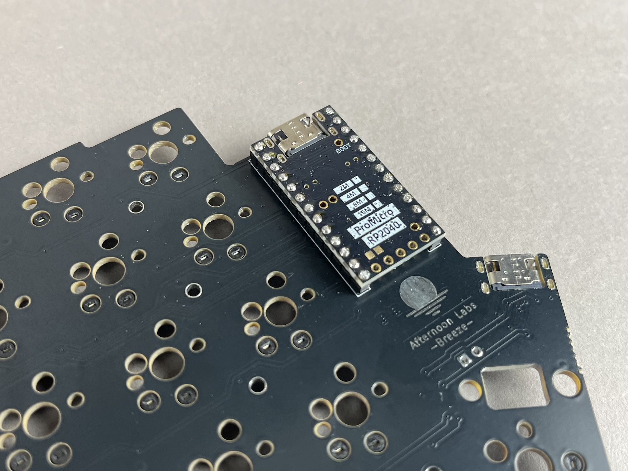
- Wired Build
- Wireless Build
Add Batteries (For Wireless Builds)
If you are using a Wireless Bluetooth controller and are installing batteries, you have two options for adding them.
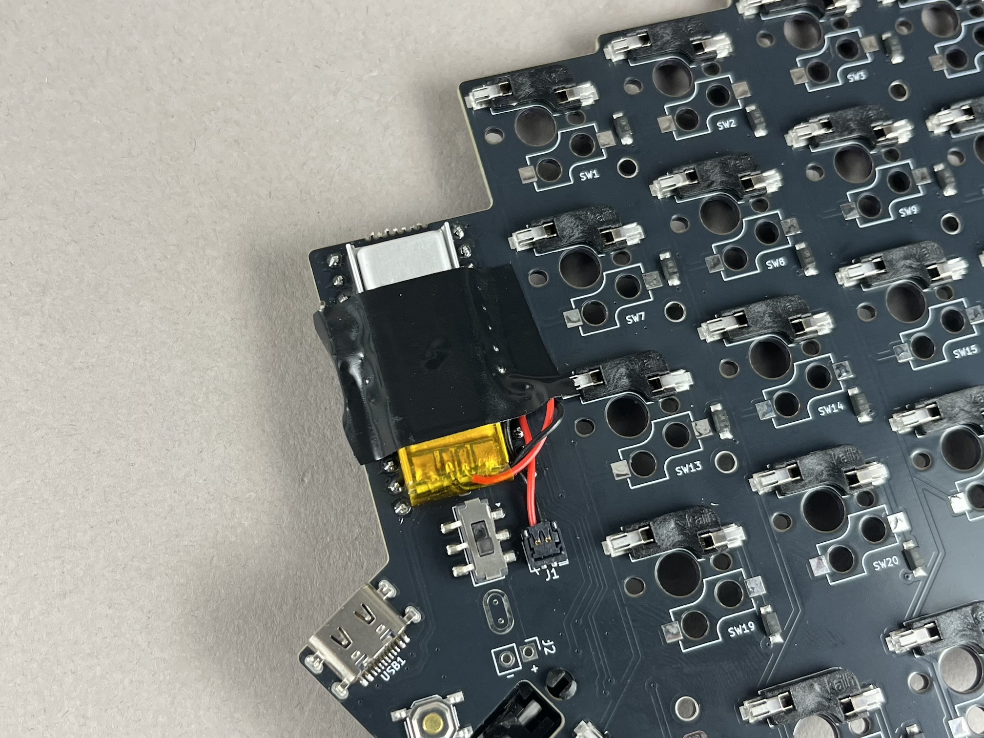
Option 1: Battery with Pico-EZmate Connector
If you have purchased Li-ion batteries from Keebio, they have a Pico-EZmate connector on the end of them for easier installation.
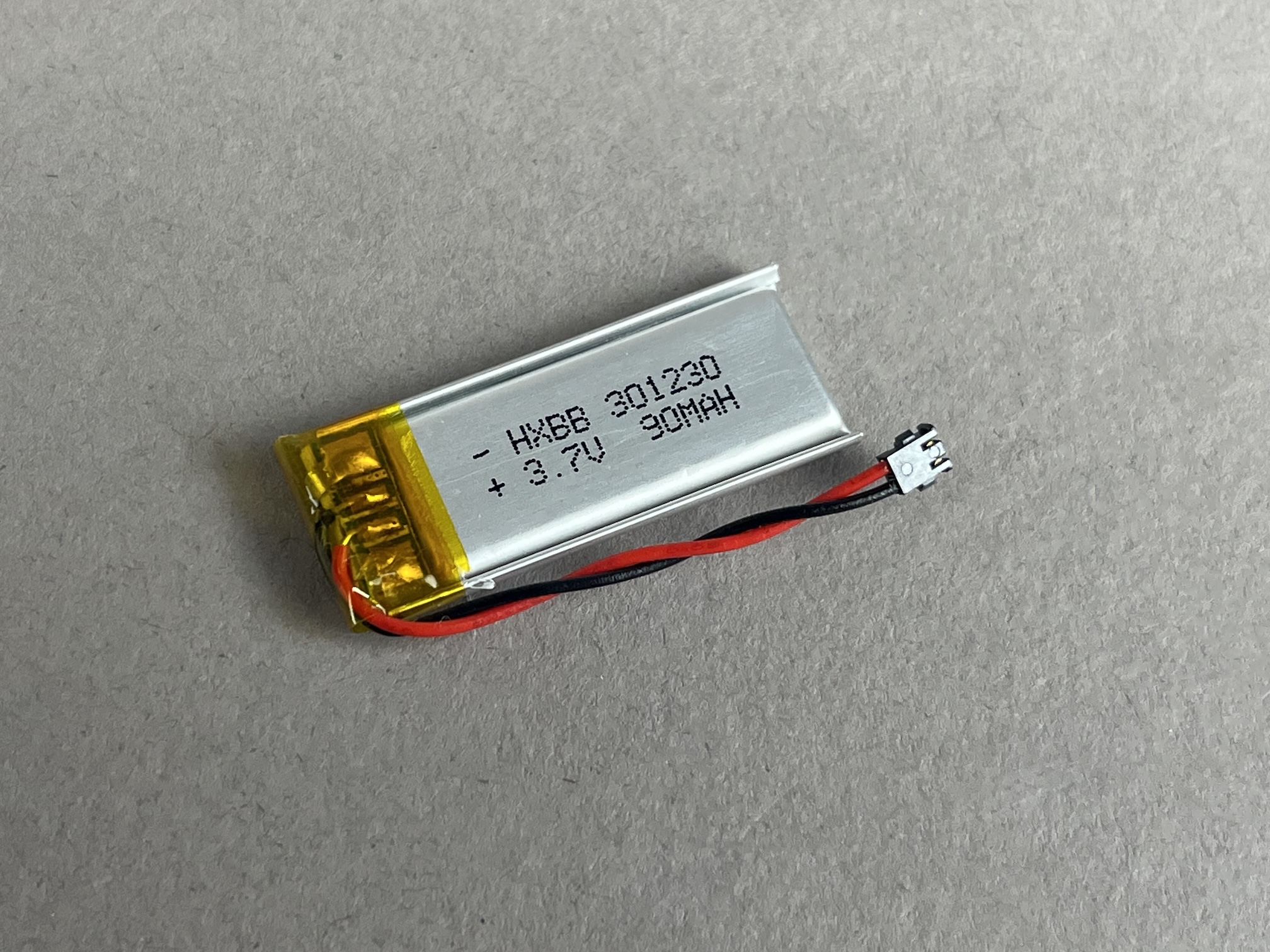
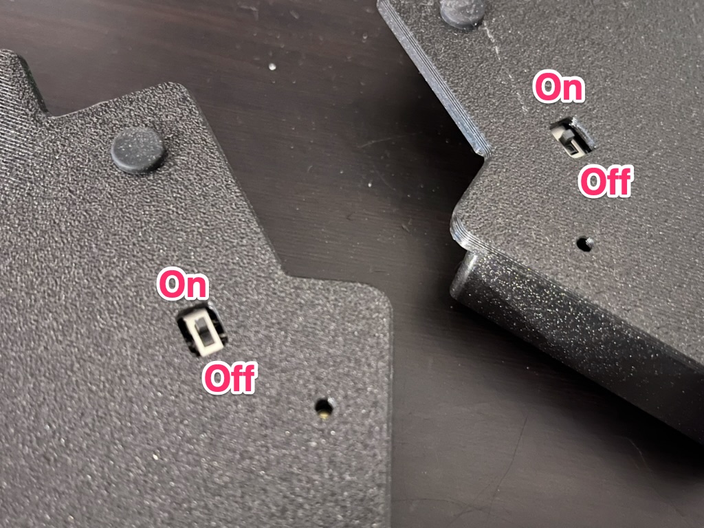
First slide the battery power switch down, which is the Off position.

Next, press the connector onto the PCB where the Pico-EZmate connector is.
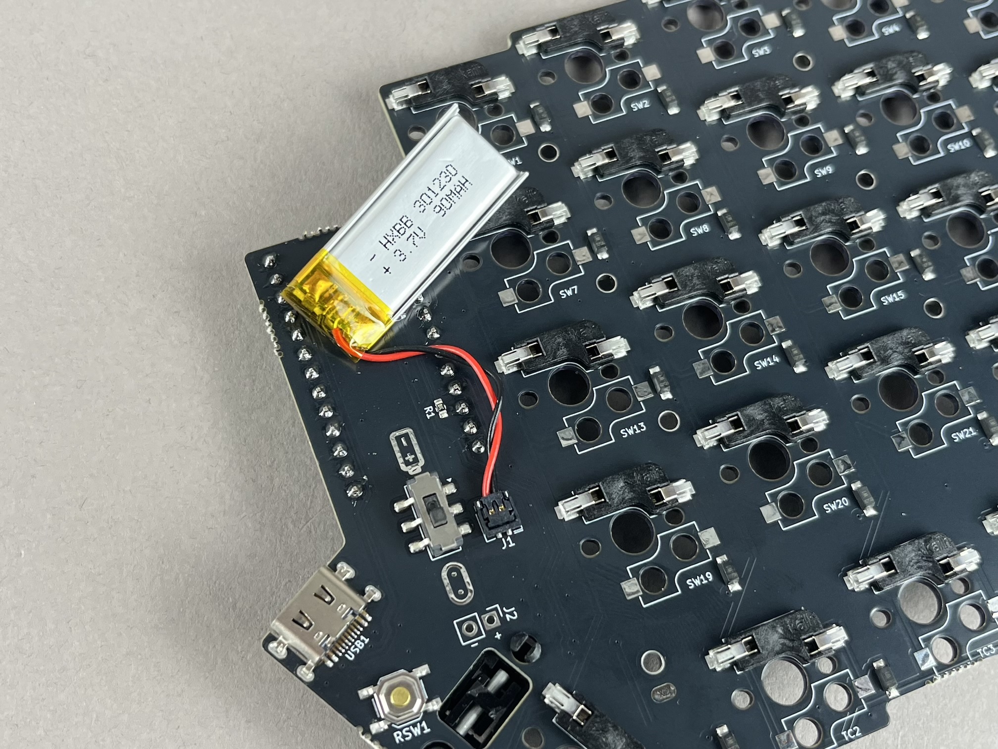
Add a piece of tape to hold the battery in-place.
Option 2: Battery without connector
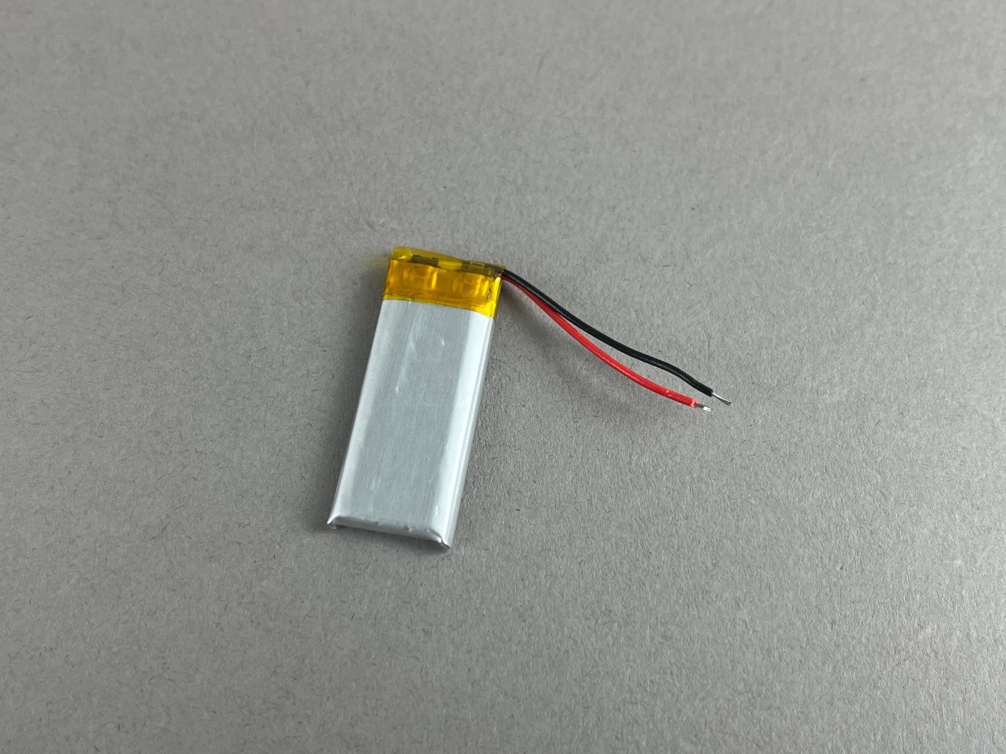
If you are bringing your own batteries that don't have Pico-EZmate connectors, you can solder them to the PCBs.
First slide the battery power switch down, which is the Off position.
Next, if there's a pre-existing connector at the end of the battery, cut it off and strip the ends of the wires.
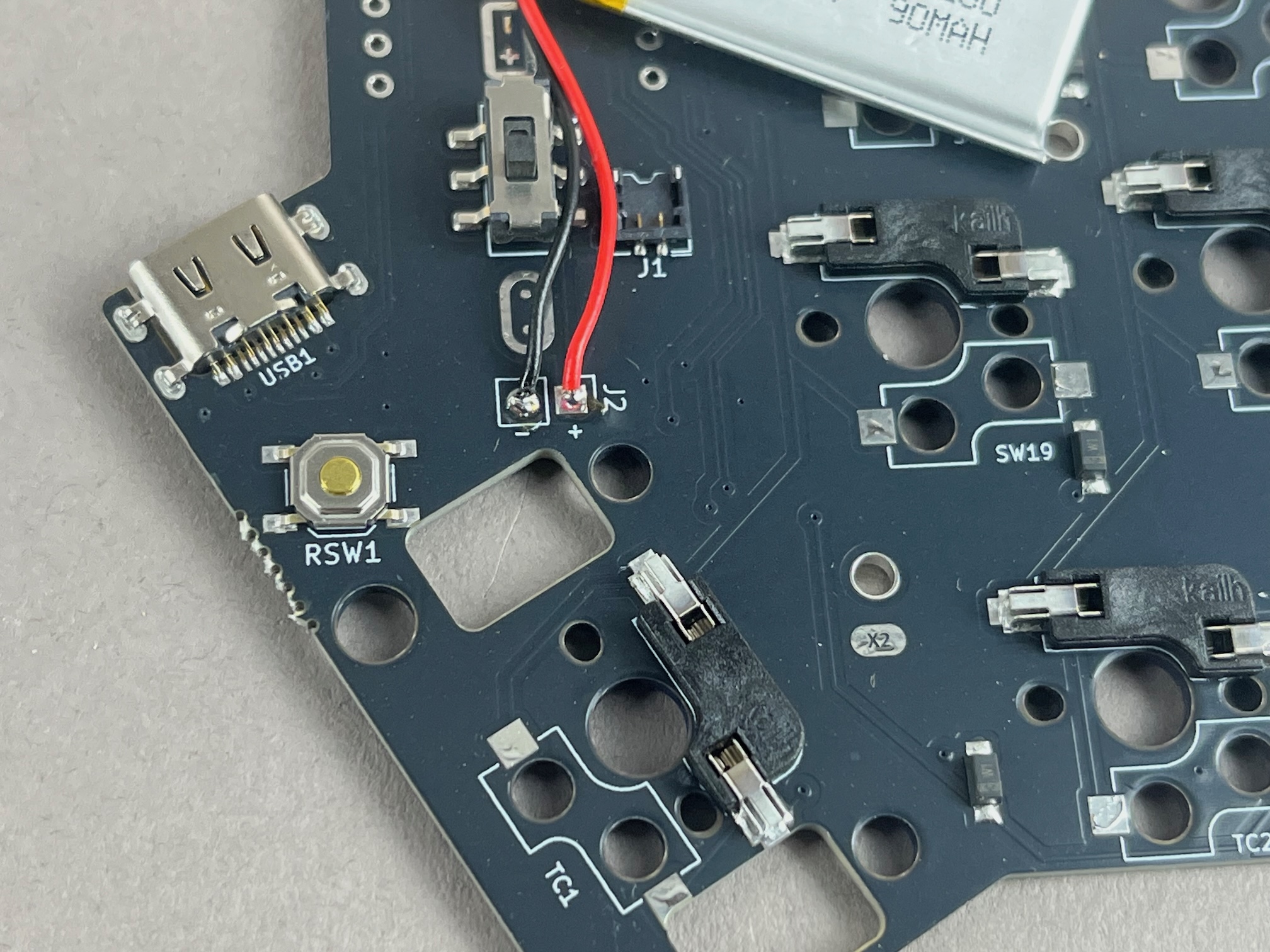
Then solder the black wire to the negative (-) pad and red wire to the positive (+) pad.
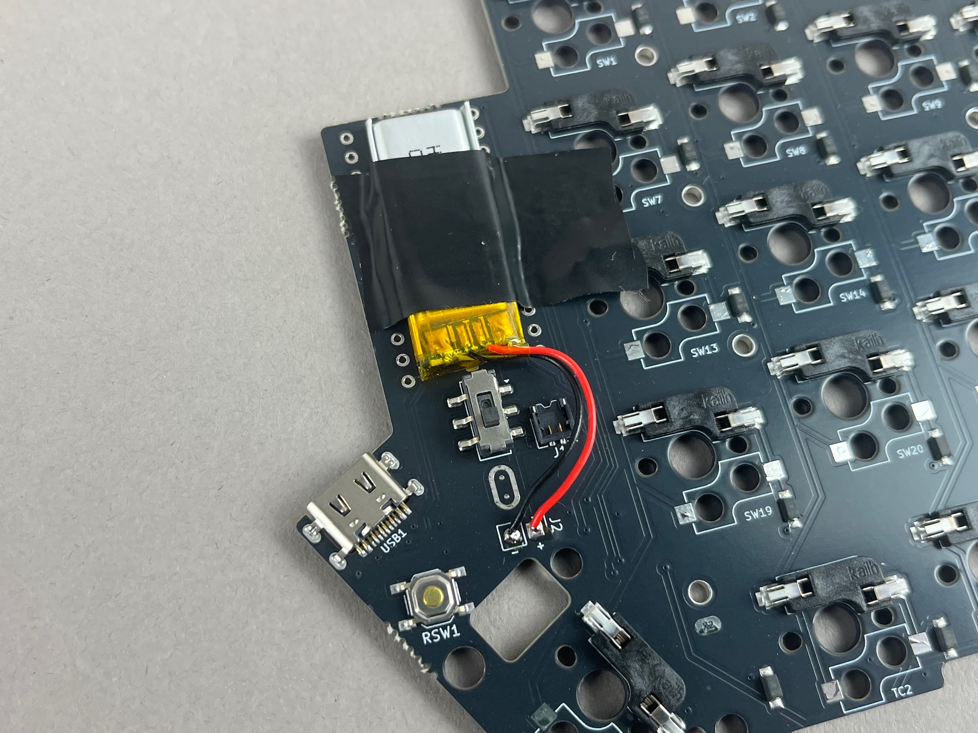
Add a piece of tape to hold the battery in-place.
Add Stabilizers
- MX Version
- Choc Version
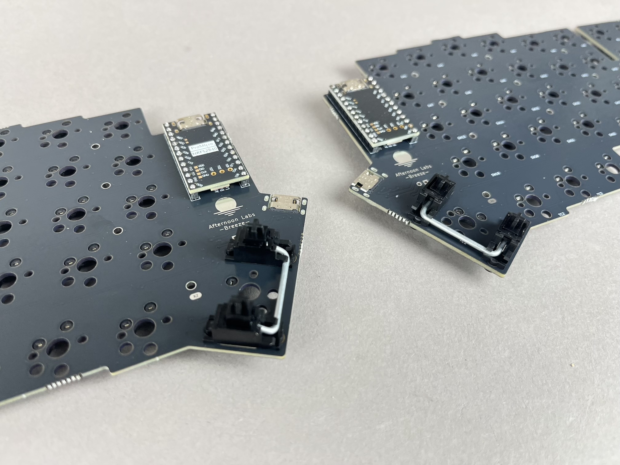
Assemble the MX stabilizers and insert them into the PCB. If you are unfamiliar with assembling and inserting stabilizers, here's a guide for that: Stabilizer Handbook
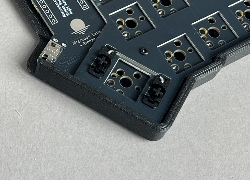
For Choc V2, stabilizers have already been installed into the plate, so you don't need to do anything else.
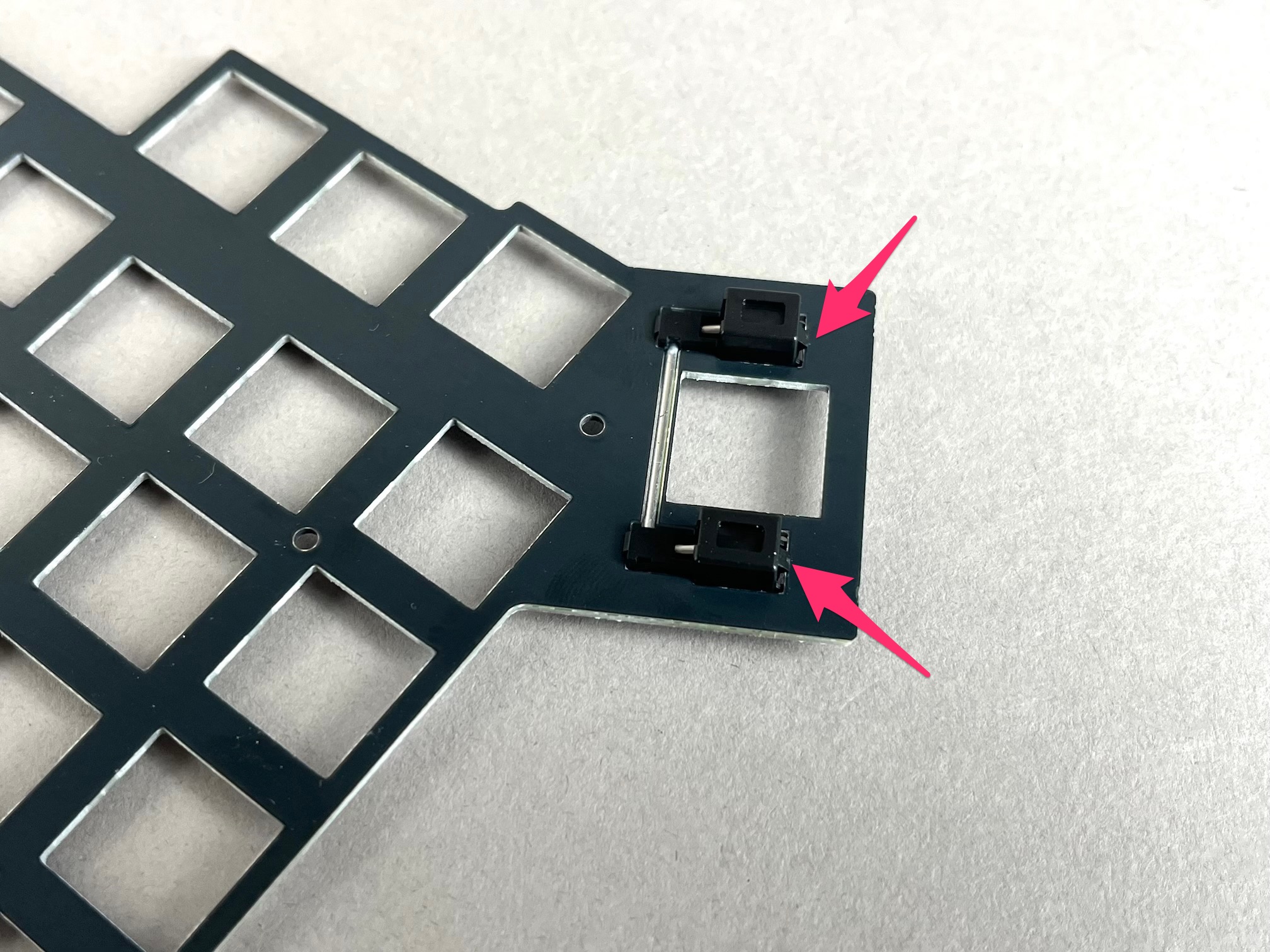
If you are using Choc V1 switches instead, the pre-installed V2 stabilizers will need to be removed, as it's not compatible with V1 keycaps. From the underside of plate, push in the two tabs marked below on the stabilizer to unhook it from the switch plate. As a result, you'll need to use the thumb key without a stabilizer.
Add Switches
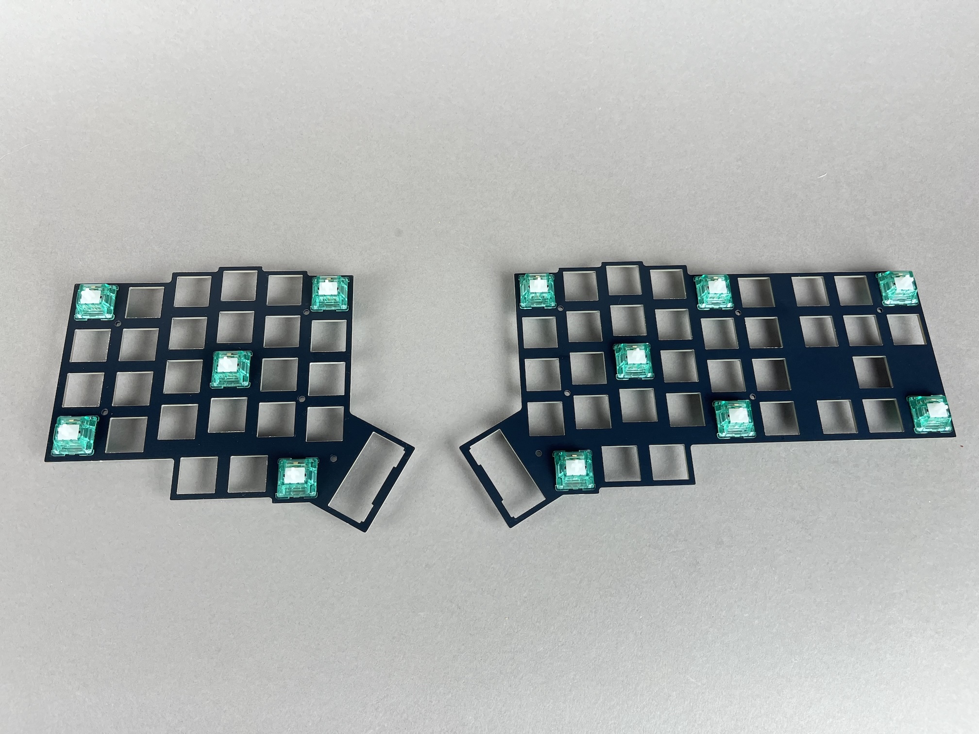
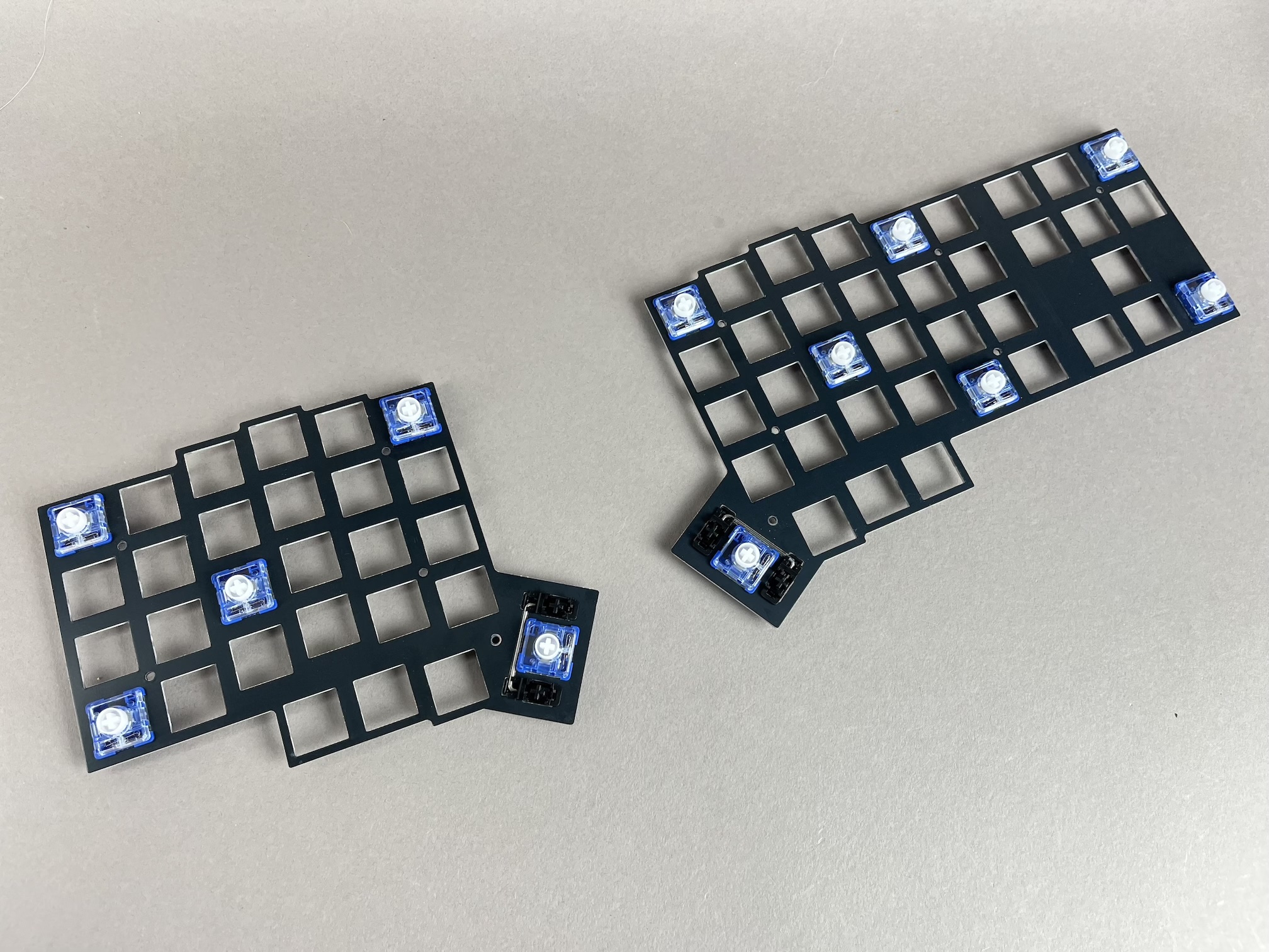
Start off by inserting switches into the switch plate at the corners and a couple spots in the middle.
- MX Version
- Choc Version
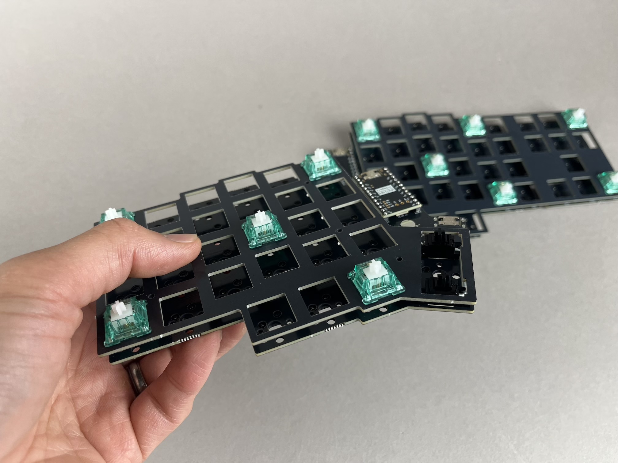
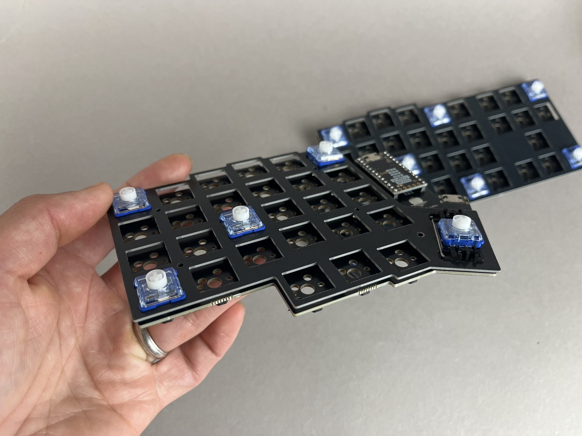
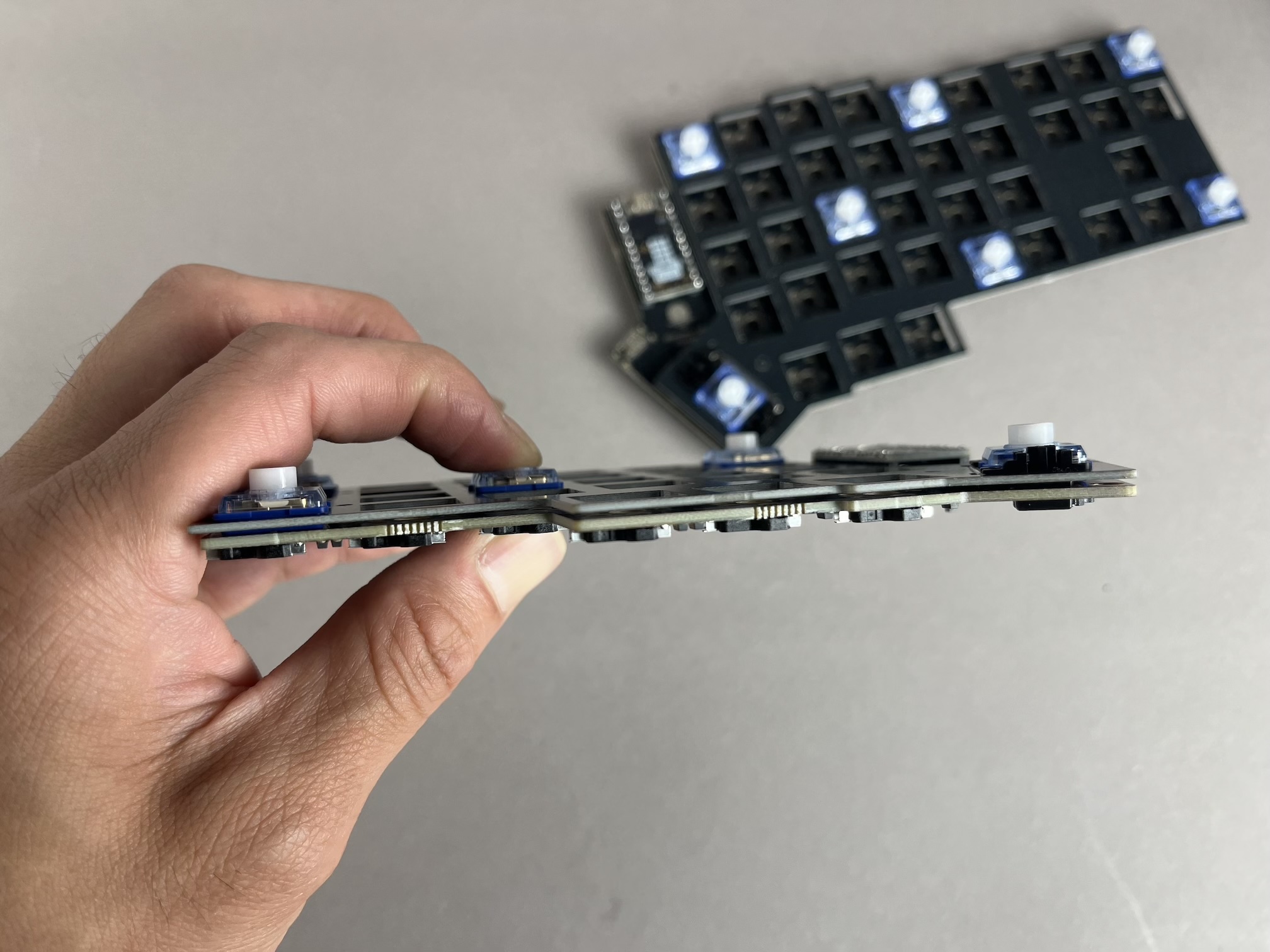
Overlay the switch plate with switches combo onto the PCB and push them together.
- MX Version
- Choc Version
Don't attempt to insert switches with bent pins into the hotswap socket, as that can push the socket off of the PCB and damage it.
- MX Version
- Choc Version
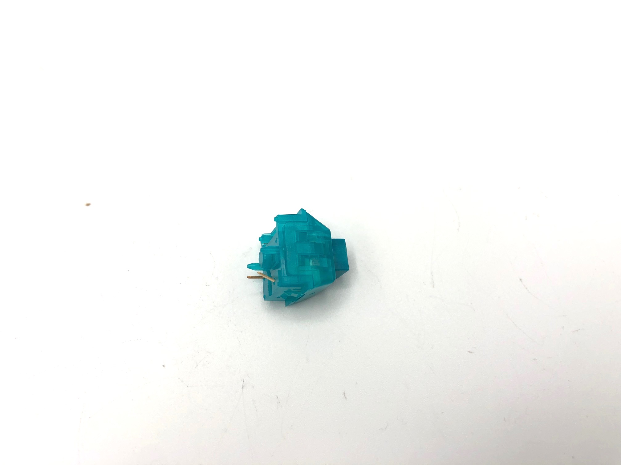
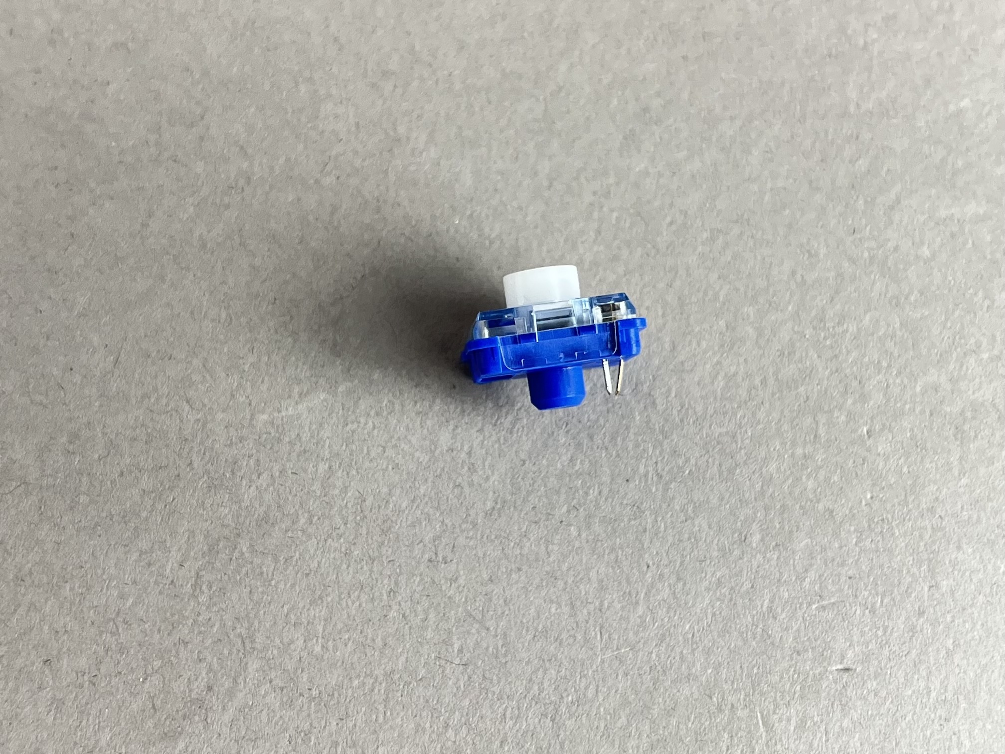
If you have a switch with a bent pin, unbend the pin. Sometimes it helps to have something like a pair of tweezers to straighten out the pin.
- MX Version
- Choc Version
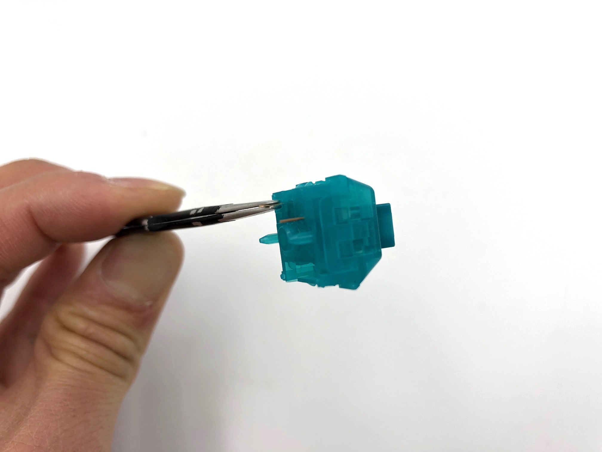
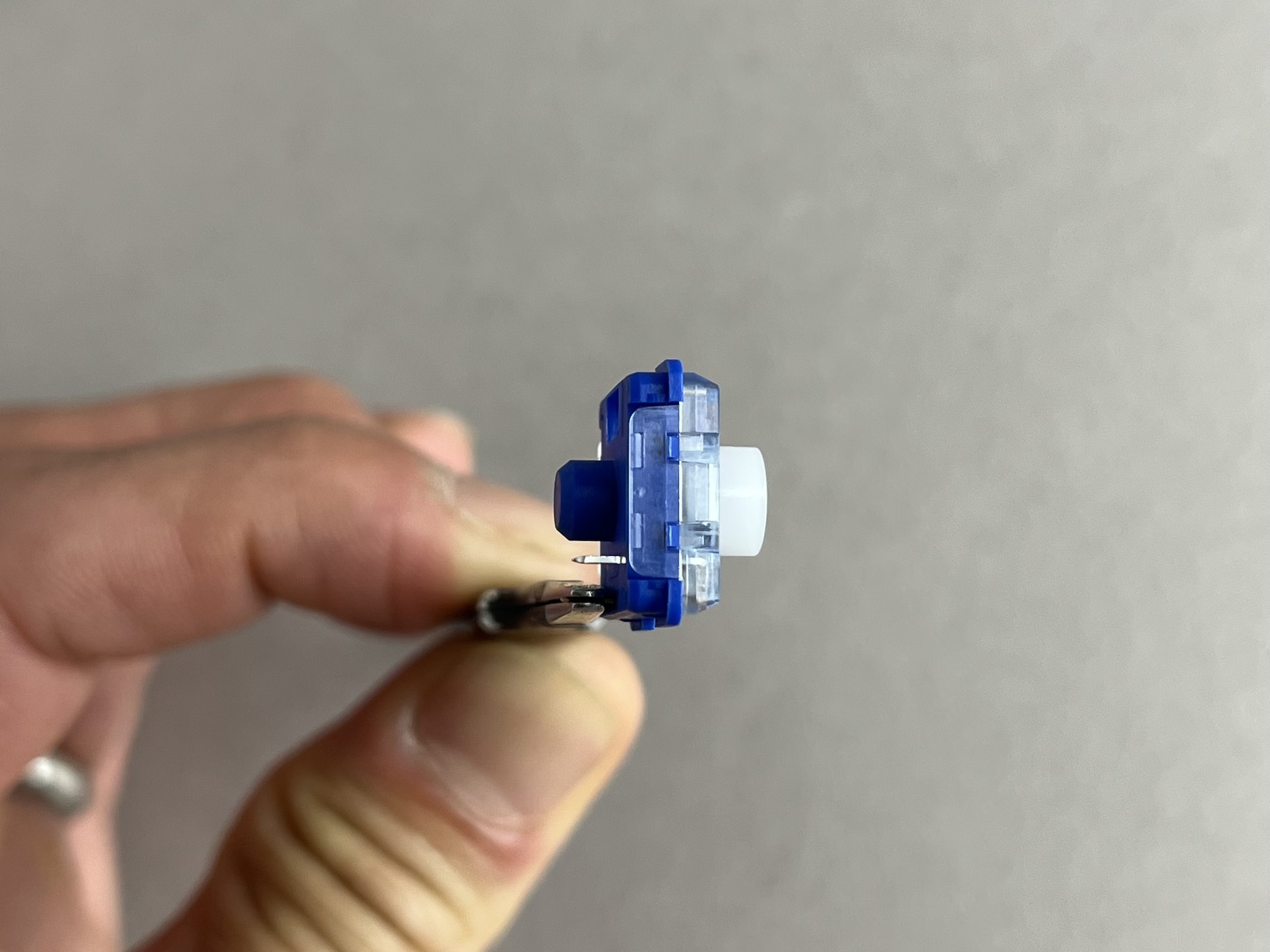
- MX Version
- Choc Version
When together, there should be a 3.5mm gap between the switch plate and the PCB.
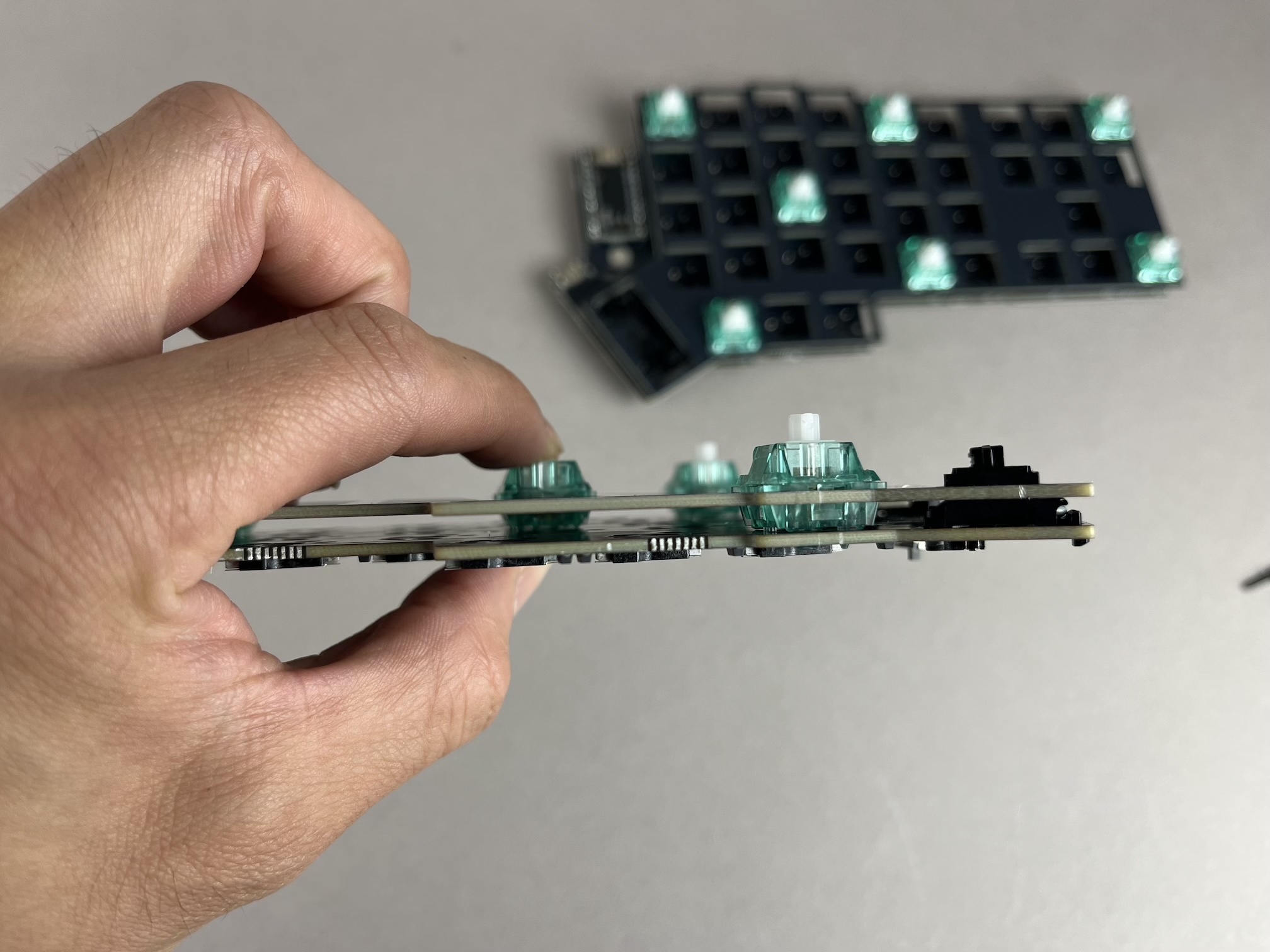
When together, there should be a 1mm gap between the switch plate and the PCB.
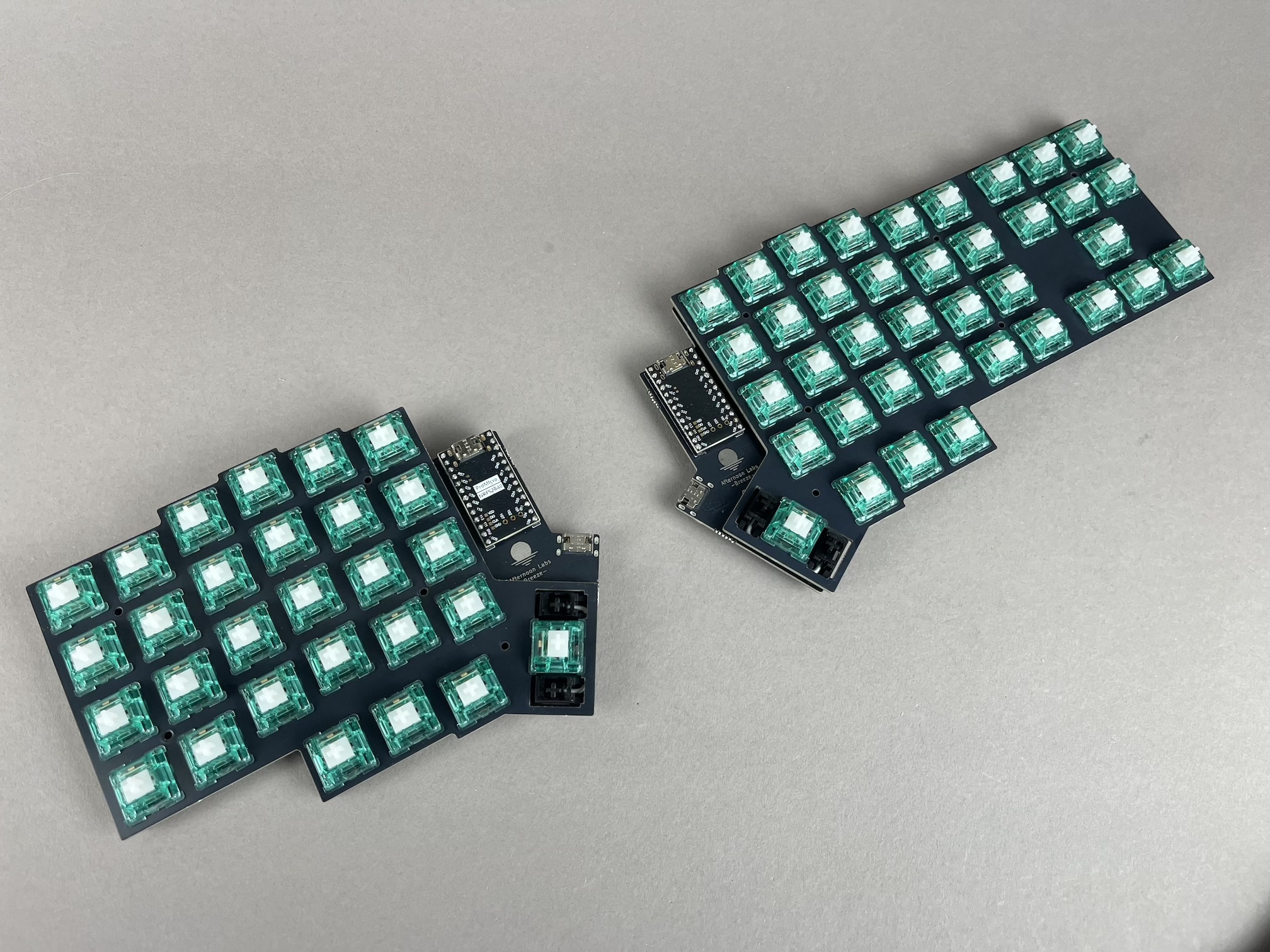
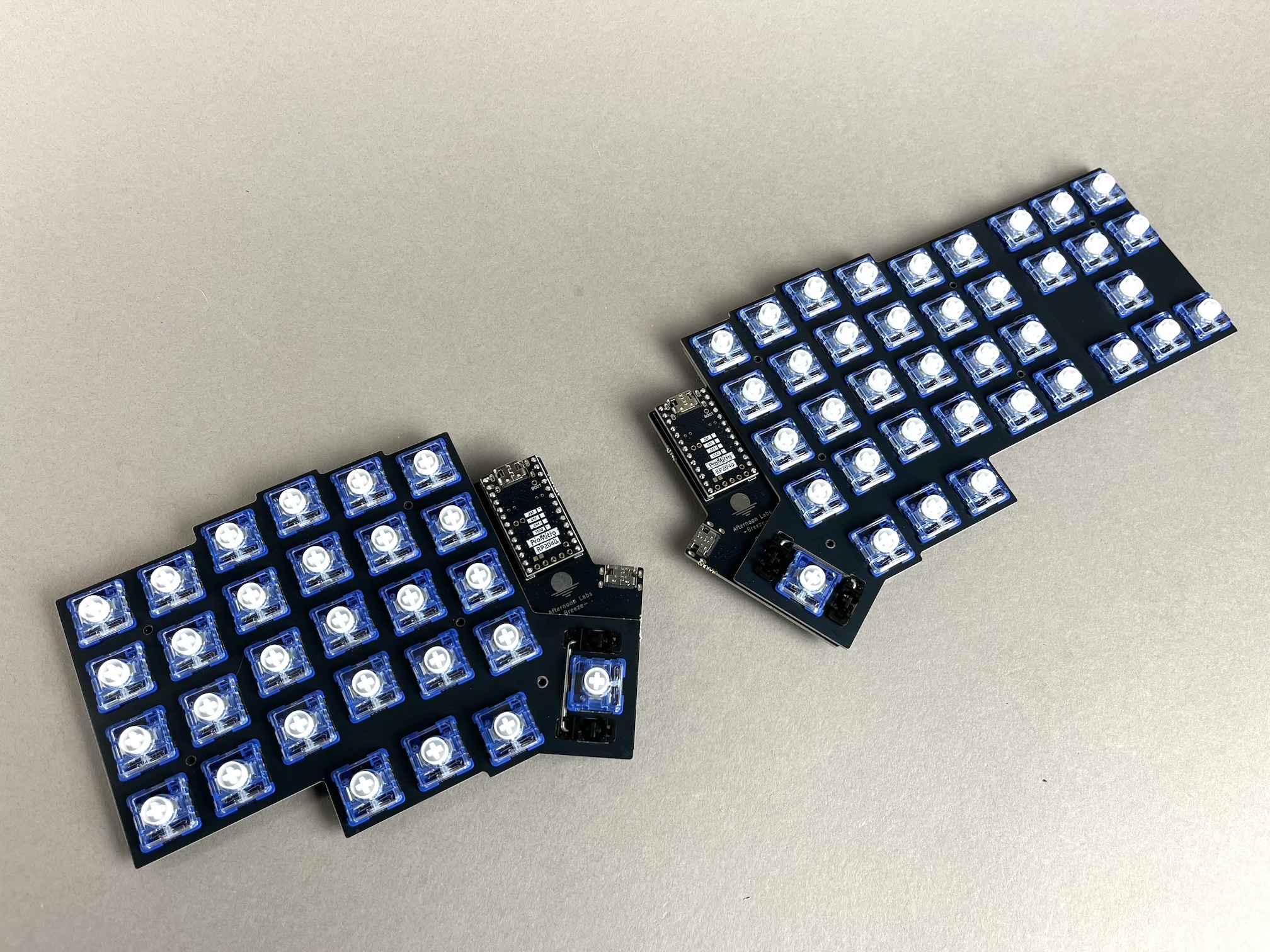
Add the rest of the switches to the plate/PCB.
- MX Version
- Choc Version
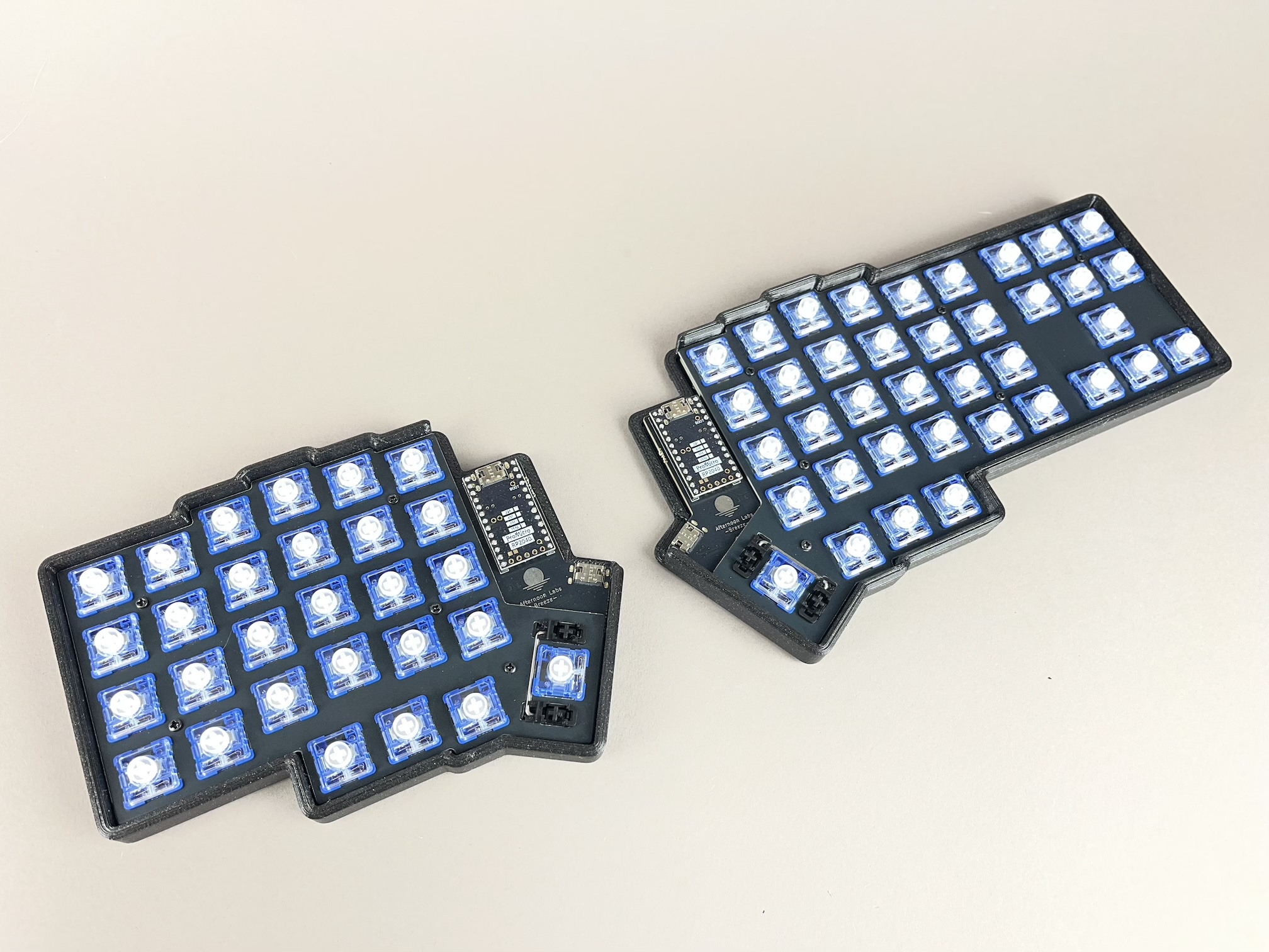
Assemble Case
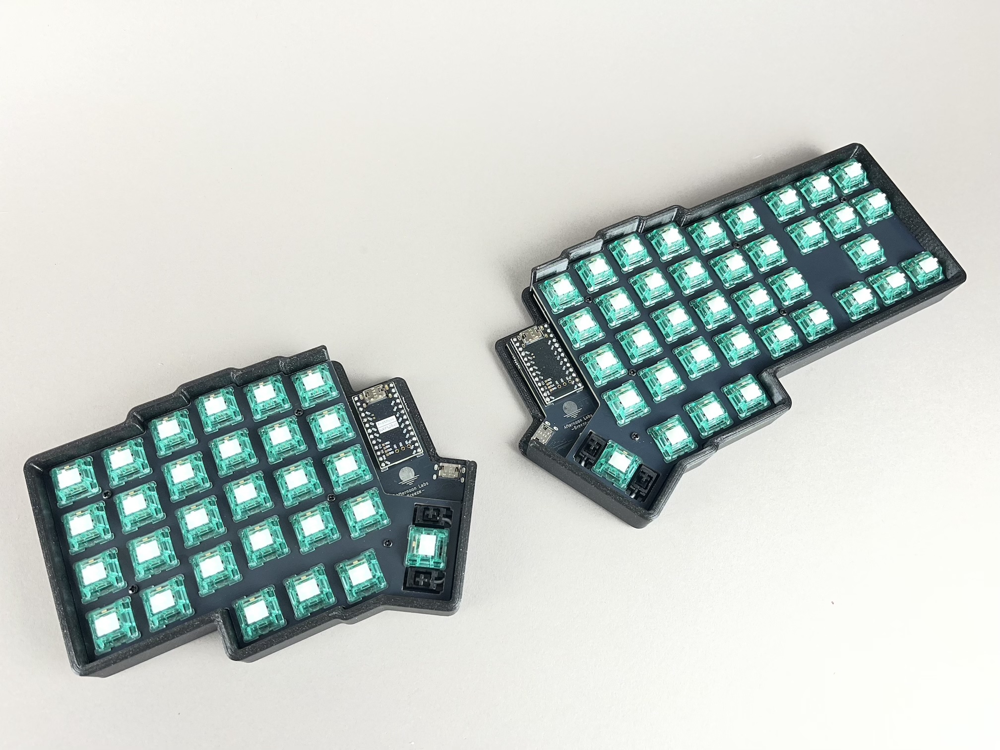
Line up the PCB/plate into the case and screw it in with the screws. Do not screw in the screws too tightly, as this will bring the plate too close to the PCB and the switches will pop out.
- MX Version
- Choc Version
Add Keycaps
Finally, add your keycaps to your board.
- MX Version
- Choc Version
Board Notes
Remapping/reprogramming Board
Looking to remap/reprogram your board? Check out our guide for remapping your keyboard.
On the bottom of the case is a hole to that allows access to the reset button on the PCB.
- Wired Build
- Wireless Build
Connect the Halves
Use the USB-C to USB-C cable to connect the two halves together using the pre-soldered USB-C port on the Breeze PCB (not the ones on the controllers).
Battery Power Switch
The batteries are connected to the microcontrollers when the slide switch on the bottom of the board is moved to the Up position. Slide it to the Down position if you want to disconnect the battery from the microncontroller to save power.