Quefrency LM
Build Compatibility
This build guide is exclusively for the Quefrency LM.
Parts List
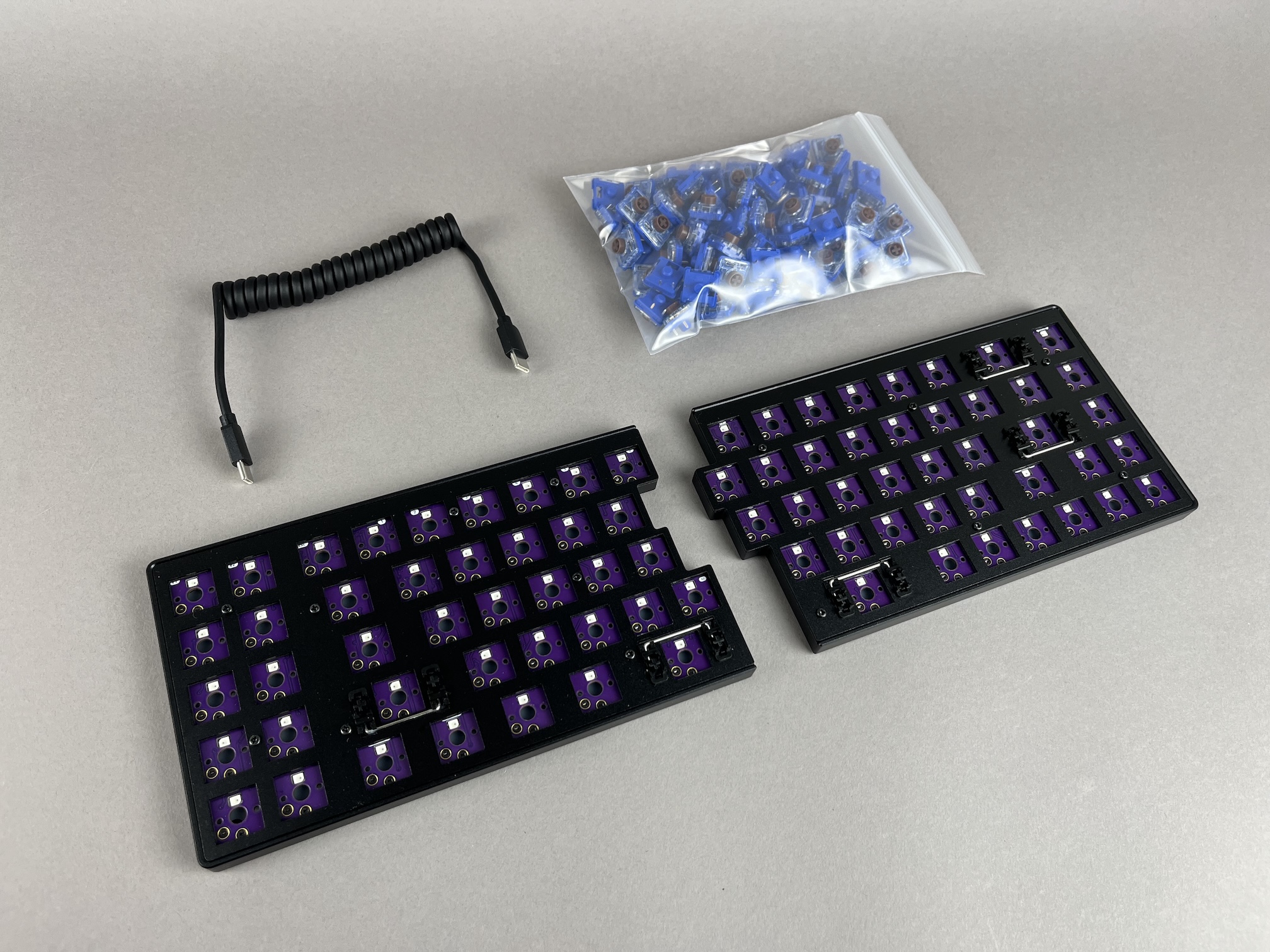
Get your parts ready:
- Quefrency LM Kit
- PCBs
- Tray Case
- Silicone liners
- O-rings
- Switch plates
- Switch plate support foam
- 8mm M2 screws
- Shroomie feet
- USB-C to USB-C cable
- Low-Profile Kailh Choc Switches - Choc V2
- Low-Profile Keycaps
Build Steps Summary
- Inspect/Test Parts
- Add switches
- Assemble Case
- Board Notes
Inspect/Test Parts
Before starting assembly of the board, check if there's any issues with the parts in the keyboard kit.
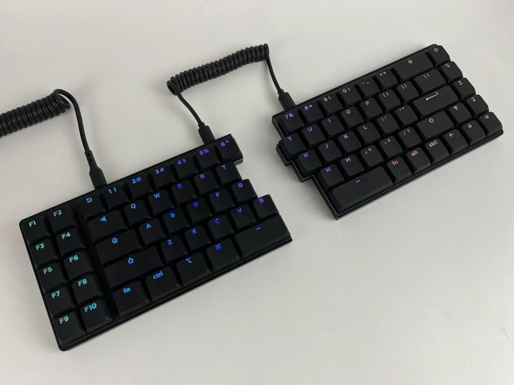
Plug in the USB-C link cable in between halves and plug in the USB-C cable from your computer to the left half. Both halves should light up. Do the same with plugging into the right half.
If both halves don't light up, check that you're plugging into the correct USB-C port (outermost ones) and that you are not using a charging-only USB-C cable.
Optional: Unscrew the switch plate and inspect that there is switch plate support foam, silicone tray liners, and o-rings on the mounting points. See Full Breakdown for more information.
Add switches
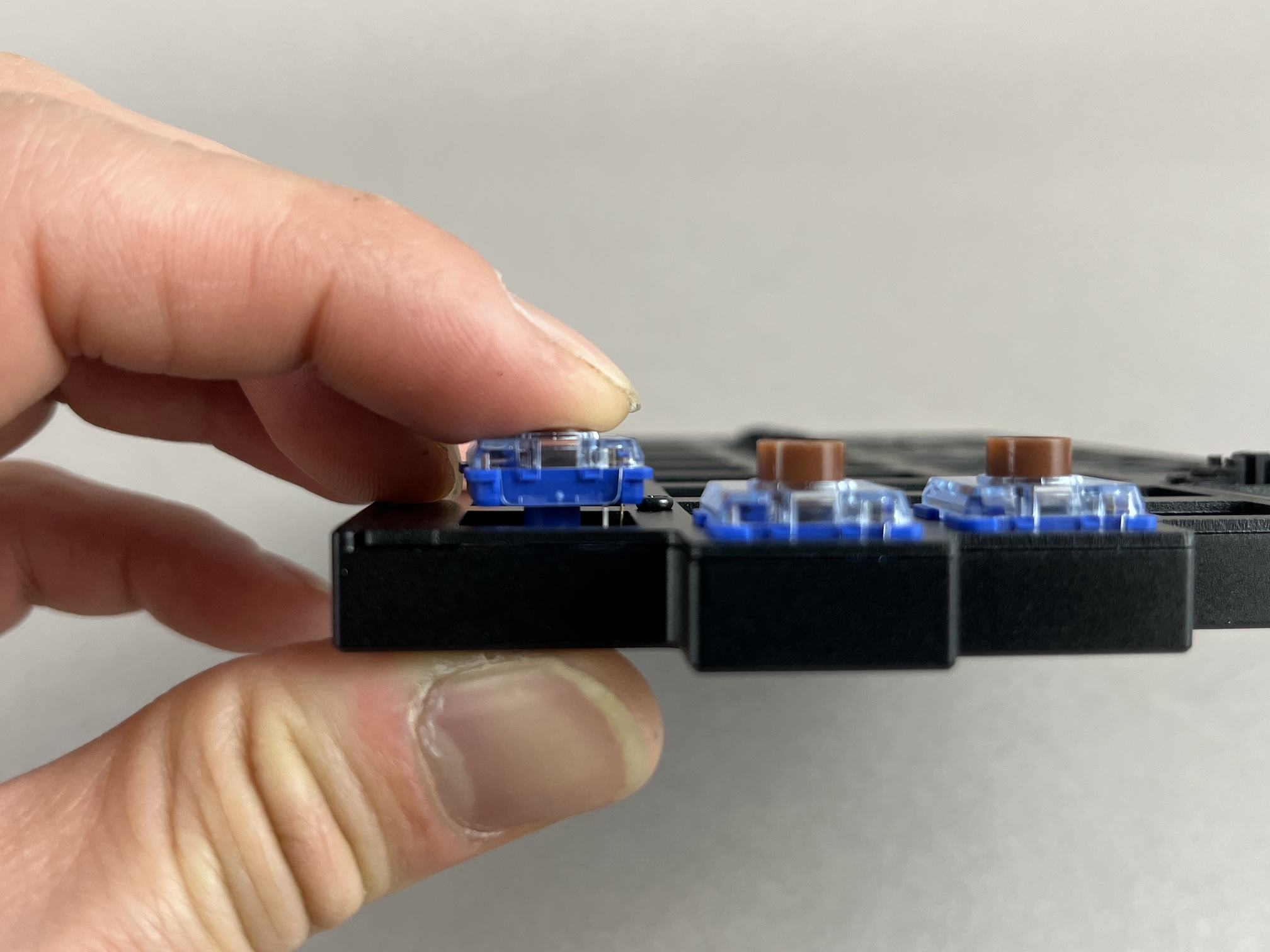
To insert a switch, make sure the pins line up with the hotswap socket on the PCB.
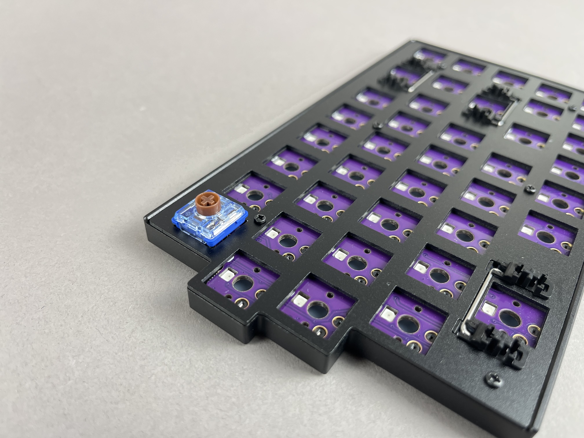
Then push down on the part of the switch that is above the pins until it clicks into place.
Add the rest of the switches.
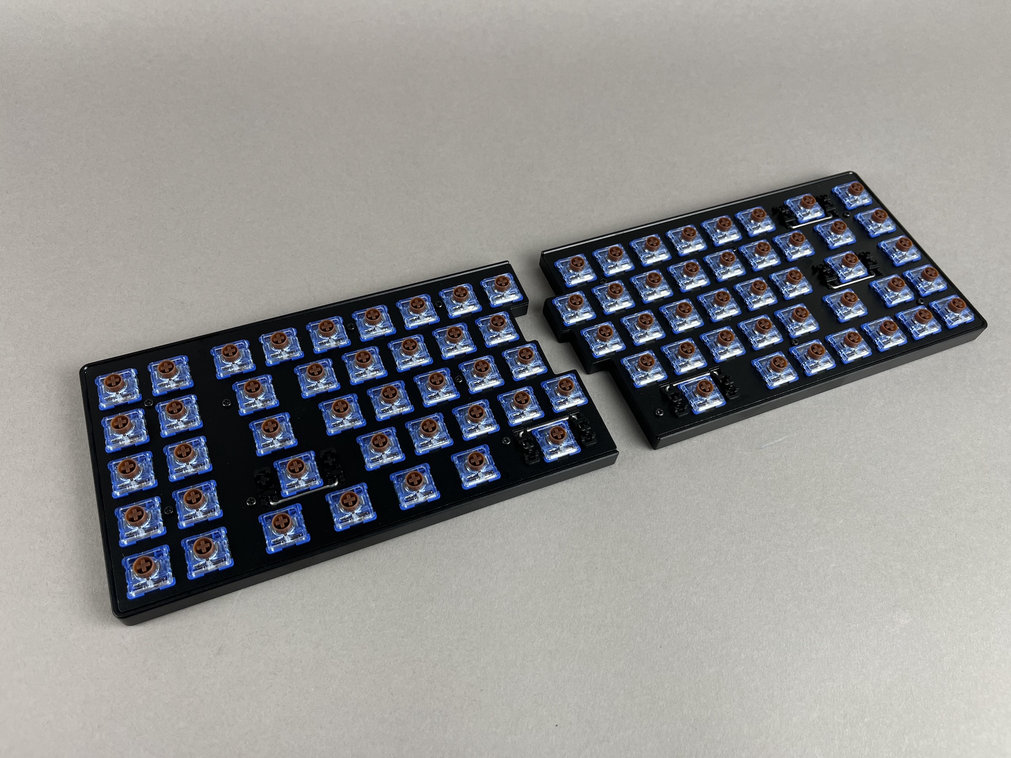
Test keys
Before reassembling the case, plug the USB cable into the PCB and test all of the keys to make sure everything is working, as it'll be easier to fix switch issues now than later.
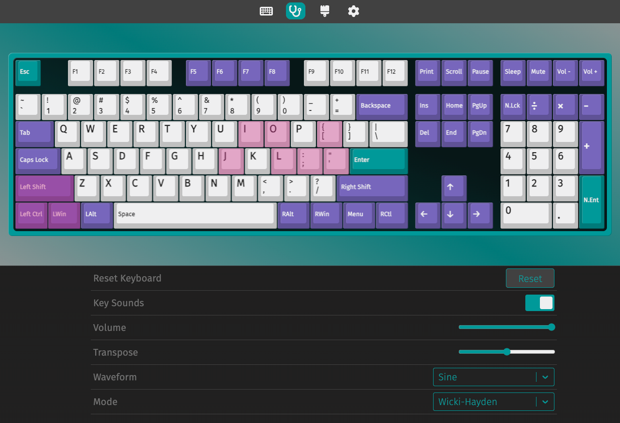
Note that the Fn key won't show up in the switch tester, as a keycode isn't sent to the computer when pressed, so to test it, hold Fn while pressing another key. For example, holding down Fn while pressing 1 will output F1 to a computer.
If a key is not working, check that the switch is inserted properly and that the pins are aligned with the hotswap socket. Sometimes, a pin can get bent during insertion, which can cause the switch to not work.
Add Keycaps
Add keycaps to all of the switches.
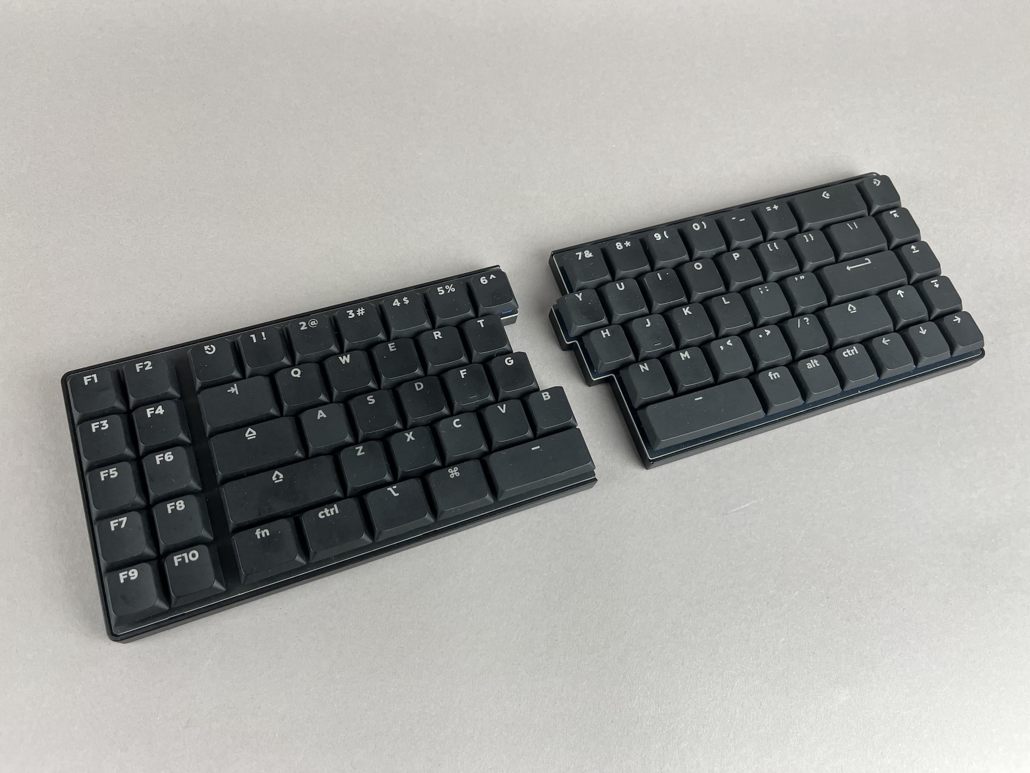
Plug it in and type away!
Magnetic Tenting Stand Rings
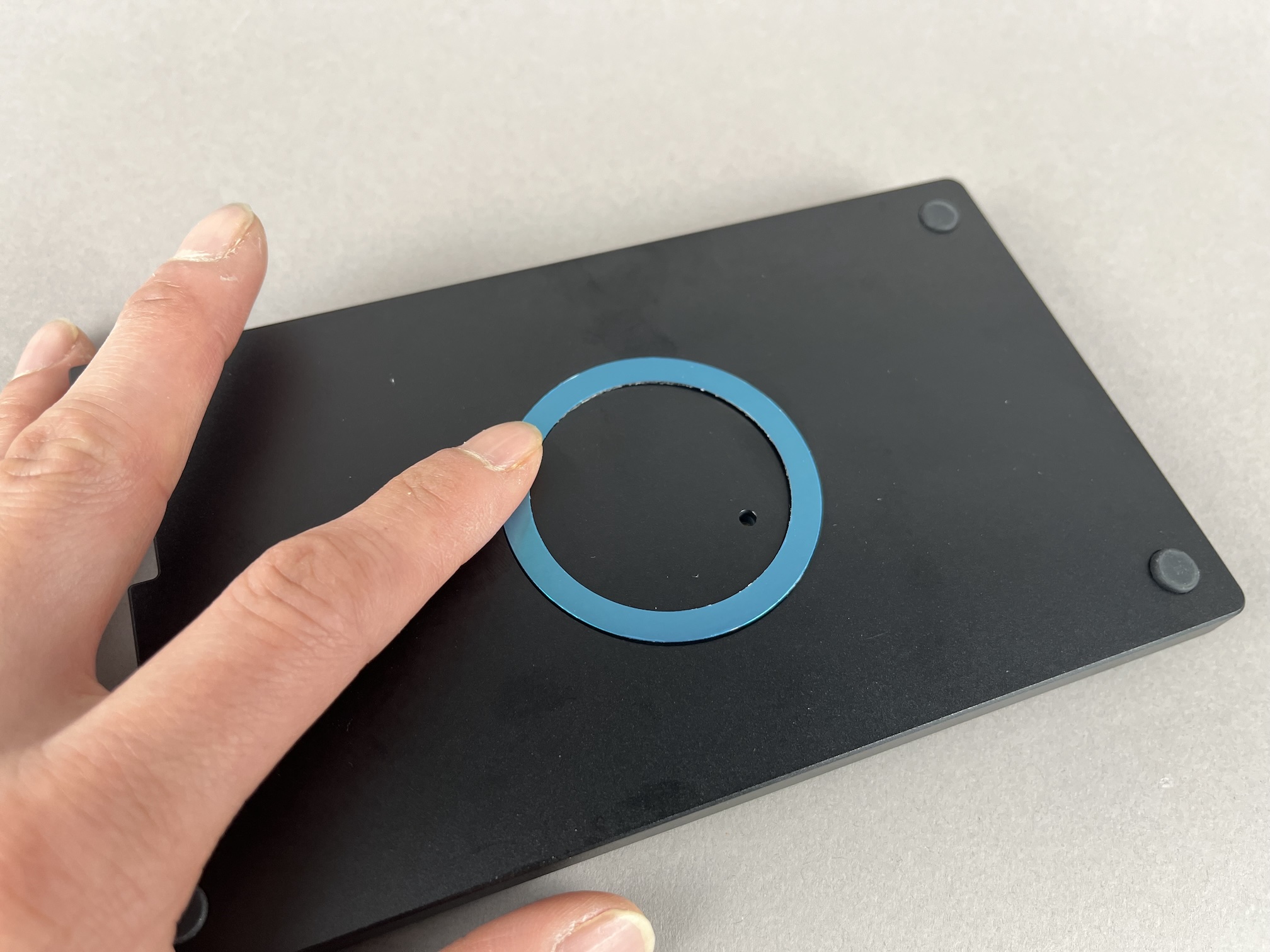
If you're using the magnetic tenting stands, you can attach the MagSafe sticker rings to the case in the circular insets on the bottom of the case.
First peel off the backing of the sticker ring.
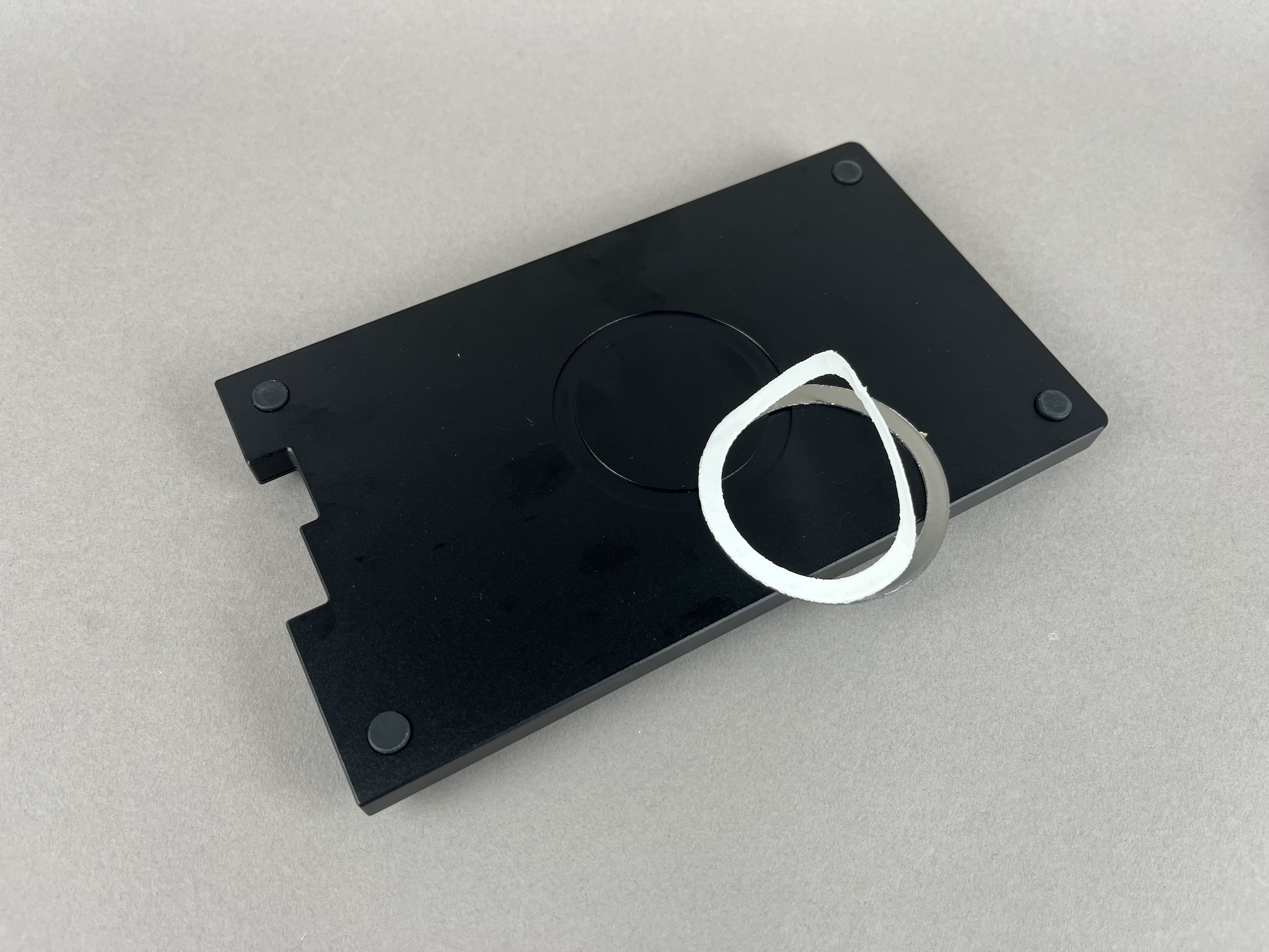
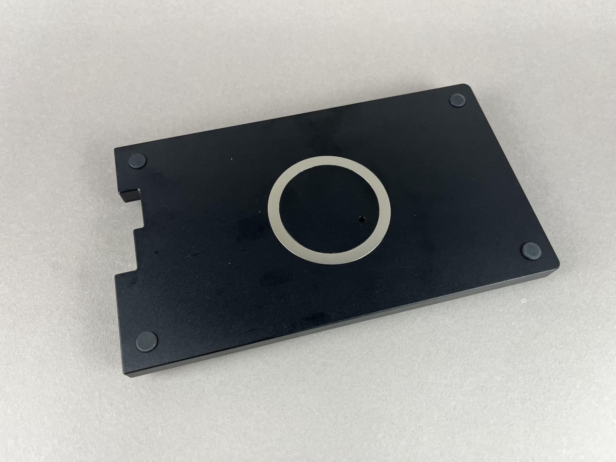
Then stick it on the bottom plate.
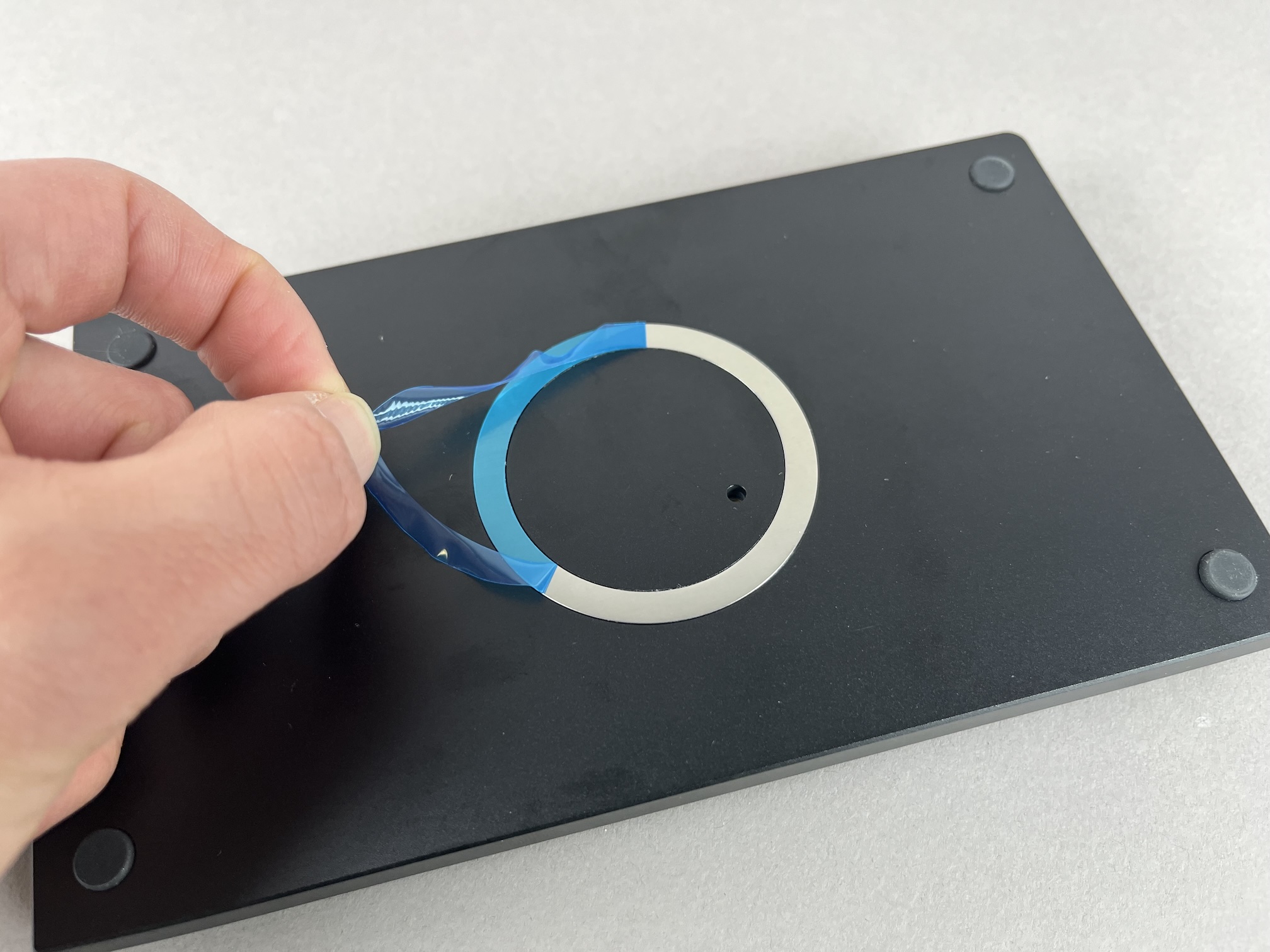
Next peel off the blue protection film.
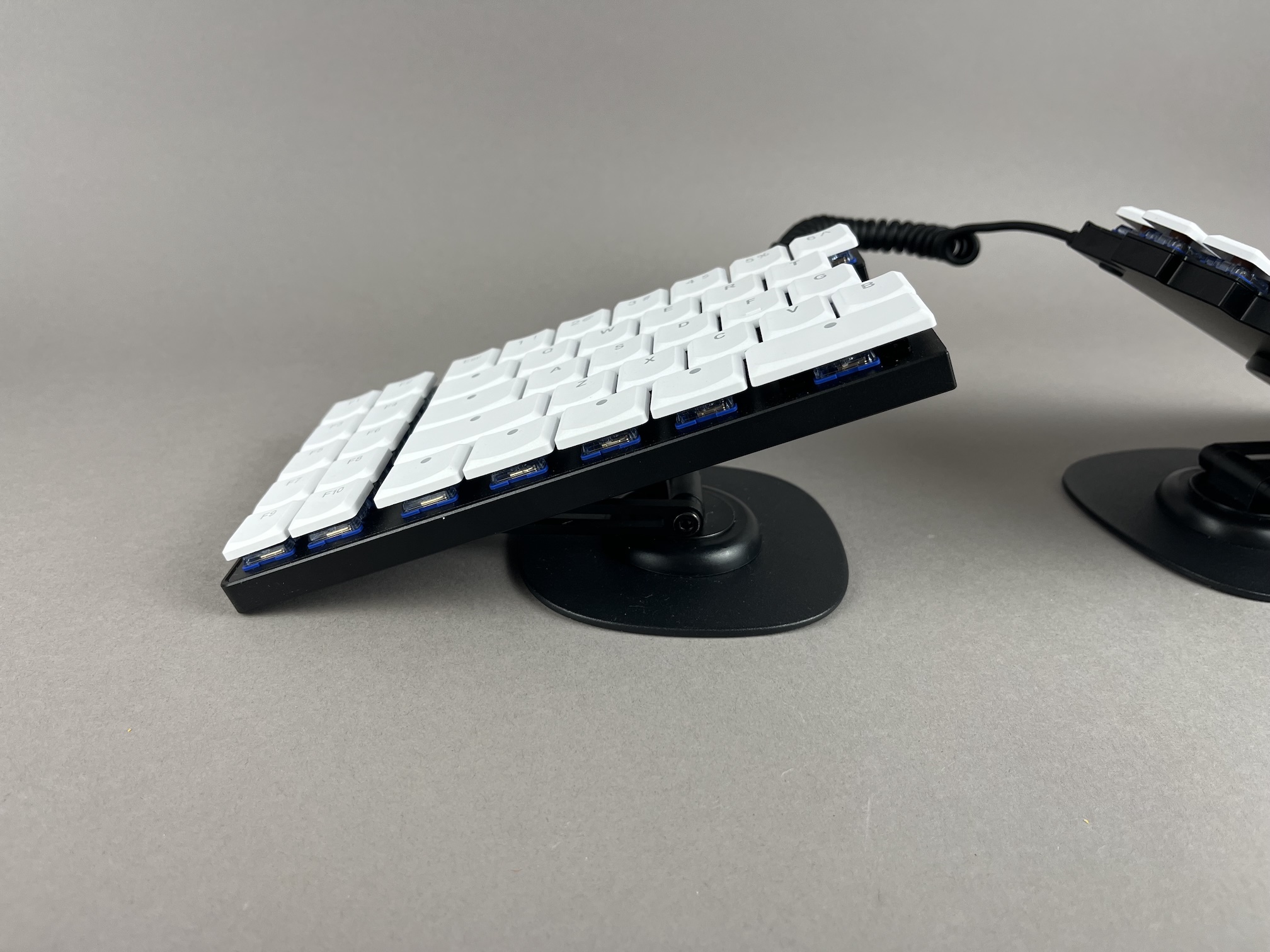
Adjust the tenting stand to however you'd like it an place the keyboard on it.
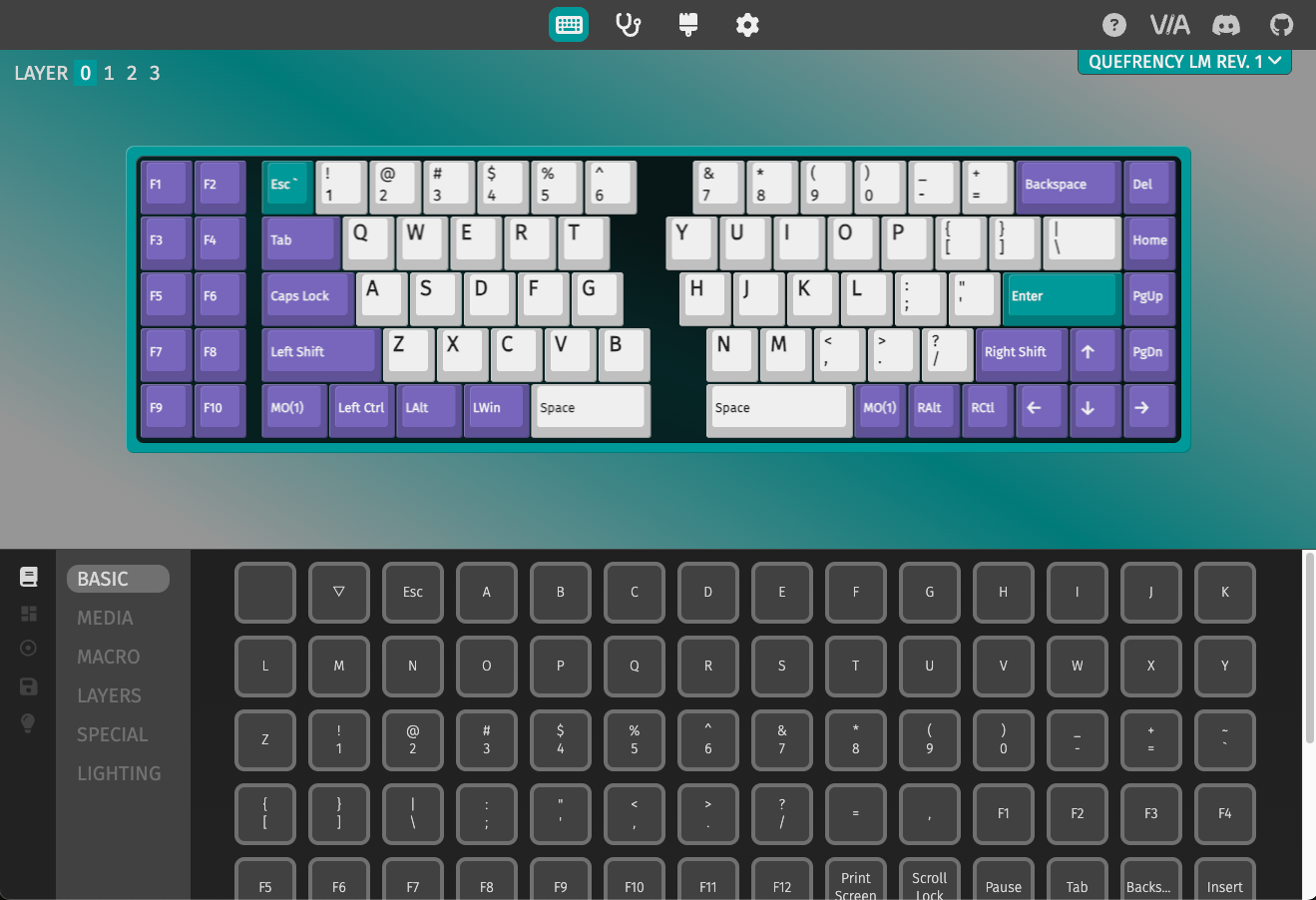
Default Keymap
Here's the default keymap if you need it: Quefrency LM Default Keymap
Remapping/reprogramming Board
Looking to remap/reprogram your board? Check out our guide for remapping your keyboard.
While the bottom plates have a hole at the bottom to allow you to access the reset button to allow your Quefrency LM to be reflashed if you are using QMK, if you don't want to be flipping your board over to press reset, you can also use one of the following options when remapping your Iris:
- Use VIA to remap your keys. The stock firmware on the Quefrency LM already has VIA support enabled. This allows you to remap the keyboard without having to reflash the board.
- If you are not using VIA and are using QMK instead, use the
QK_BOOTkeycode to reset the keyboard to allow it to be reflashed without needing to physically press the reset button on the PCB. The default way of usingQK_BOOTis by pressingFn+R.
For reference, the Quefrency LM PCB uses a STM32G431 microcontroller.
Turning off RGB LEDs
If you'd like to turn the RGB LEDs off, you can control the RGB settings in VIA.
Full Breakdown
(Images coming soon)
If you want to fully unscrew the case to check the parts inside, you can unscrew the switch plate and inspect that there is switch plate support foam, silicone tray liners, and o-rings on the mounting points.