BDN9 Rev. 1
Parts List
Here's a list of parts needed for the build:
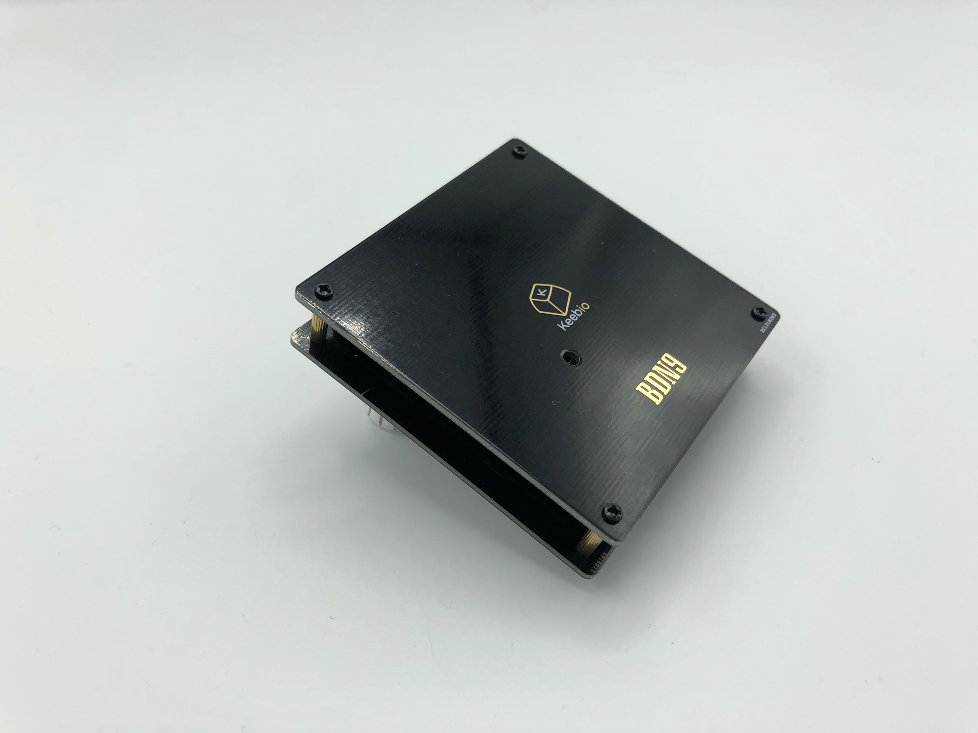
- 1 BDN9 PCB & Bottom PCB Plate with M2 screws and standoffs
- 1 Reset Switch
- 10 470Ω resistors (optional, for LED backlight)
- 1 AO3416 MOSFET (optional, for LED control)
- 9 LEDs (optional, for LED backlight)
- WS2812B RGB LED strip or 4 loose WS2812B RGB LEDs (optional, for underglow)
- 1 Microcontroller (1 of the following)
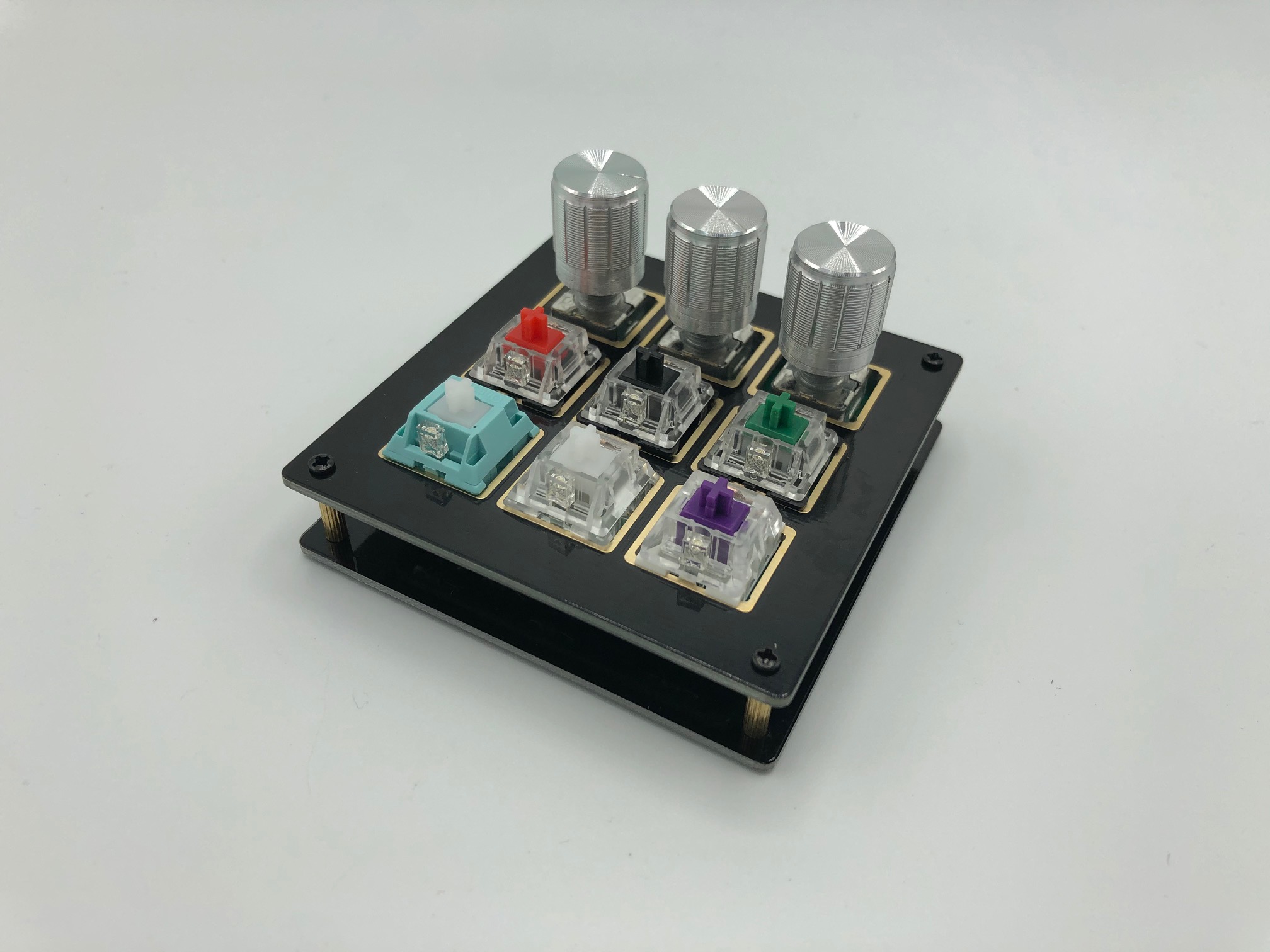
- 7-9 MX-compatible, Alps-compatible, or Choc switches
- Up to 3 EC11 or EC12 Rotary Encoders (optional)
Video of Build
Here's a build video someone has created:
Build Steps
Here's a summary of the build steps:
- Prepare components
- Solder components
- Solder resistors (for LEDs, optional)
- Solder MOSFET (for LEDs, optional)
- Solder push button
- Solder Pro Micro header pins
- Solder rotary encoders
- Solder switches
- Solder LEDs (optional)
- Flash Pro Micro
- Solder Pro Micro
- Solder RGB underglow LEDs or strip (optional)
- Assemble case
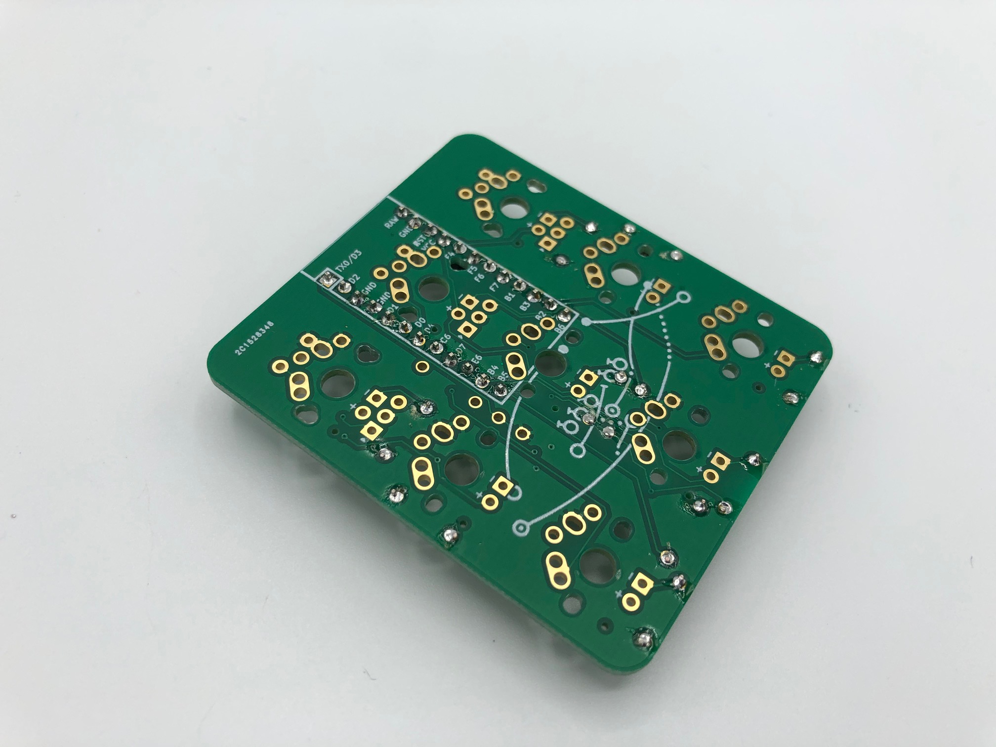
Prepare components
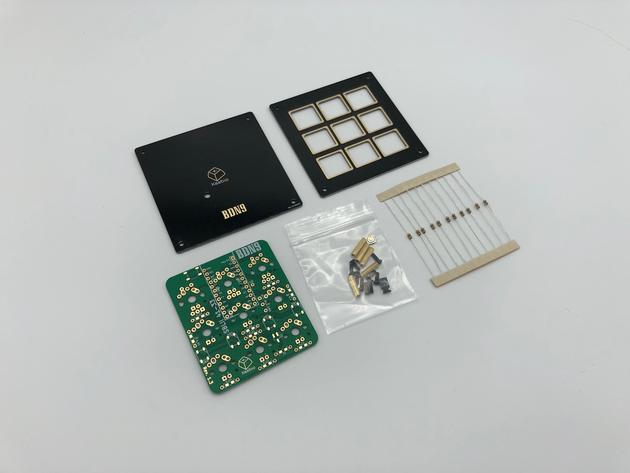
Parts from the kit.
Solder Components
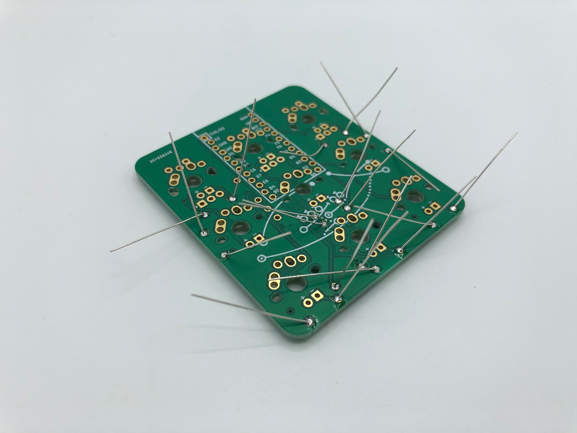
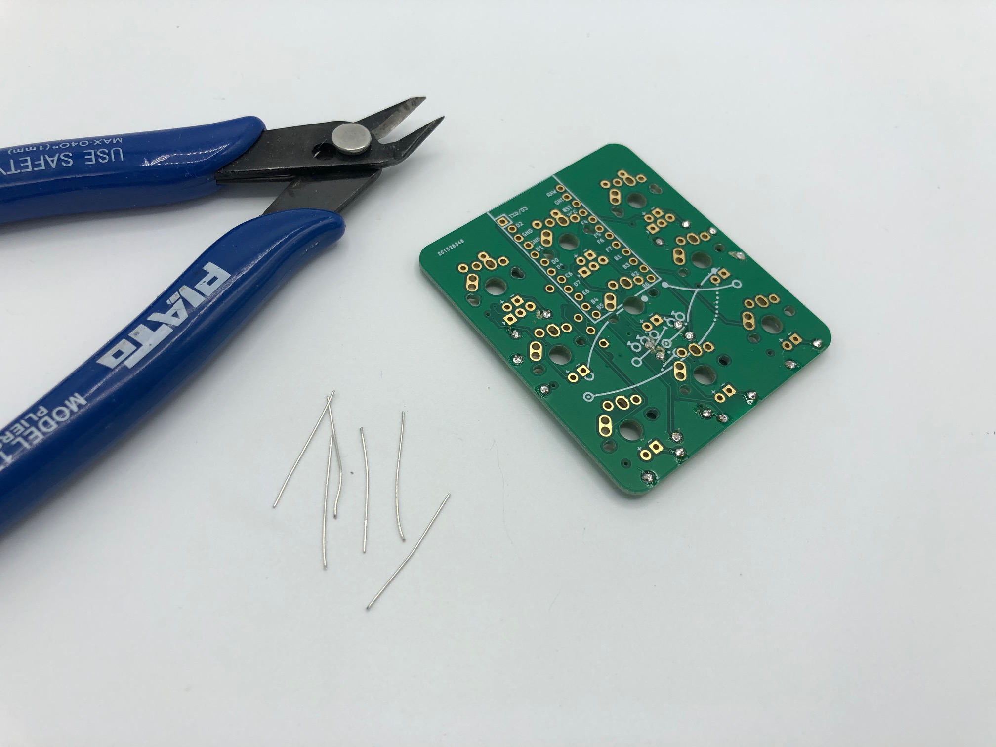
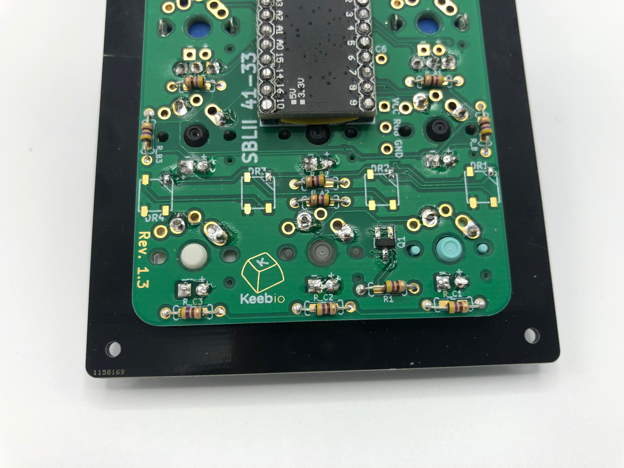
Solder resistors (optional)
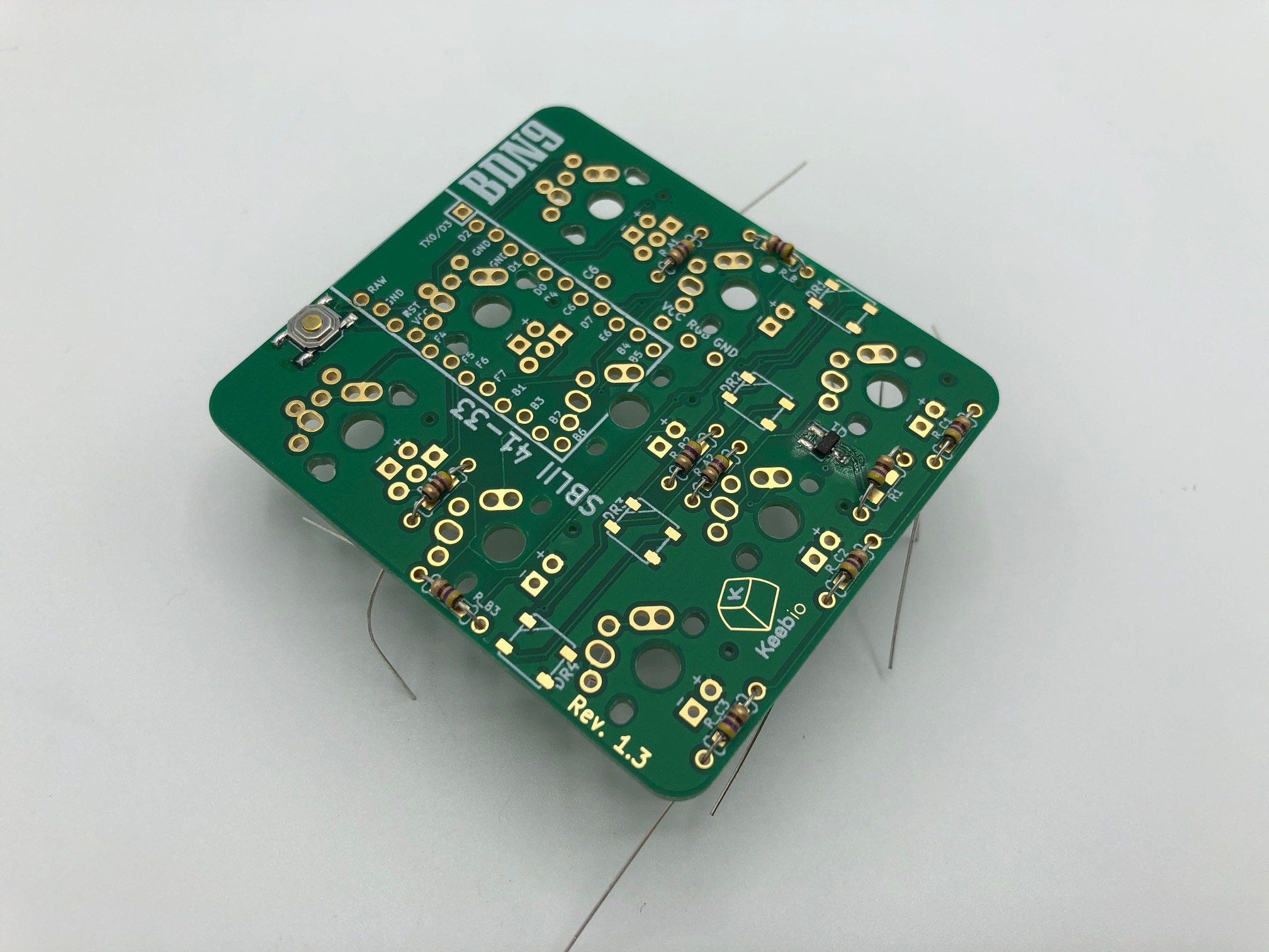
Insert all of the resistors into the PCB and solder them in. Resistors don't have polarity, so orientation doesn't matter.
Note: The resistor 'R1' can interfere with the placement of the switches on the other side if the leads poke through the PCB. Solder the resistor's leads on the same side the resistor is on and then trim the leads flush with the PCB on the other side.
Solder the MOSFET (optional)
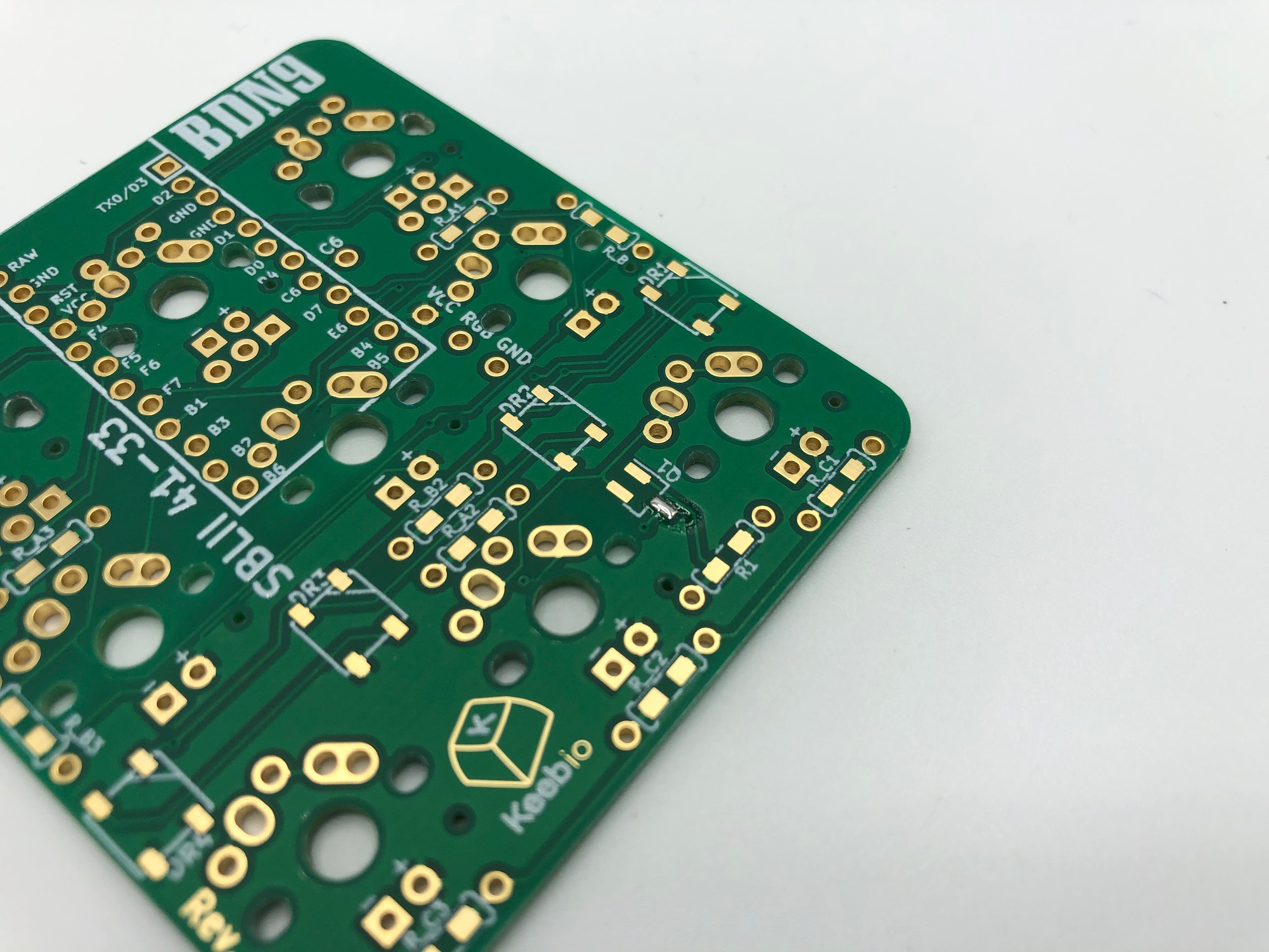
Add a bit of solder to one leg of the MOSFET pad Q1.
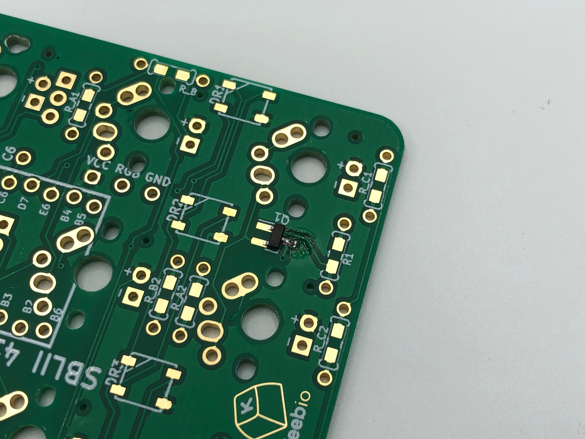
Using a pair of tweezers to hold the MOSFET, solder one leg of the MOSFET first, and make sure it is aligned properly before proceeding.
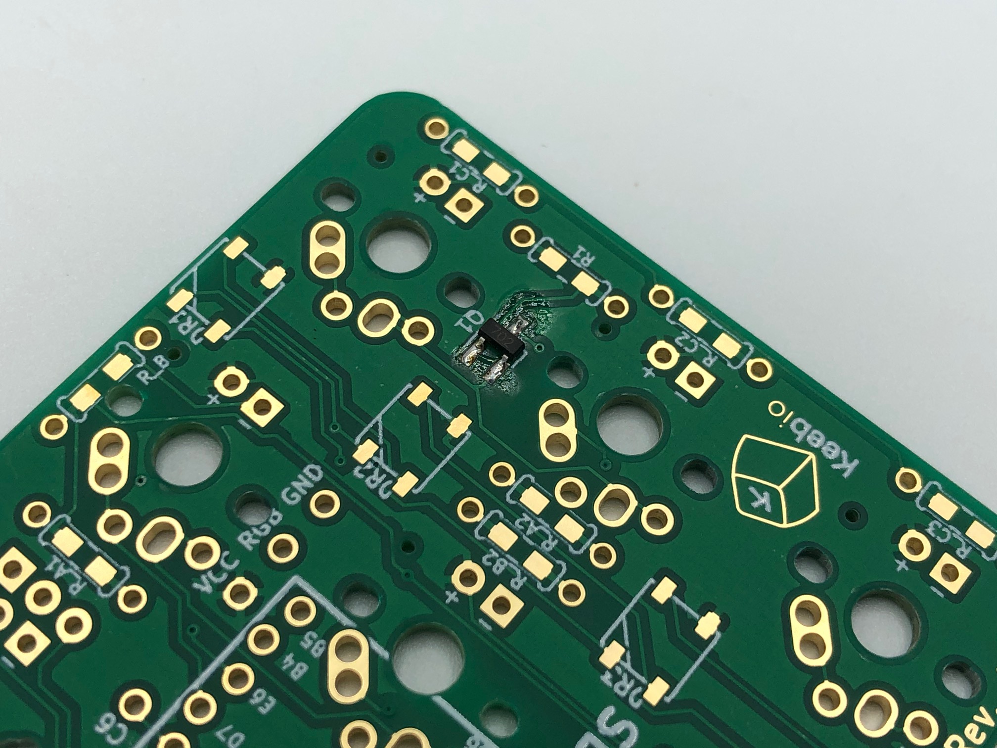
Now that the MOSFET is soldered on straight, solder the other two legs.
Solder the reset button
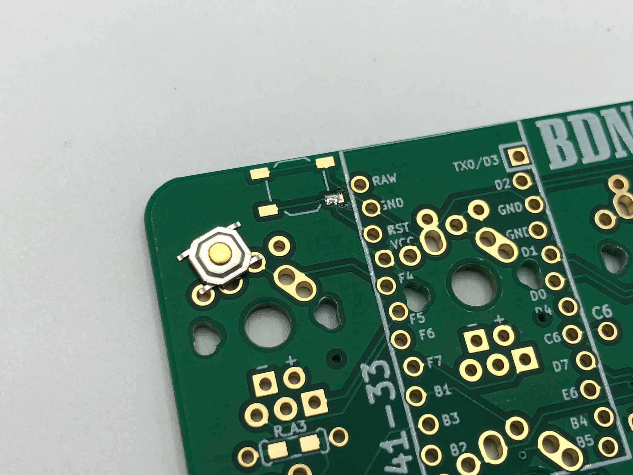
Add a bit of solder to one pad of the reset switch location on the PCB.
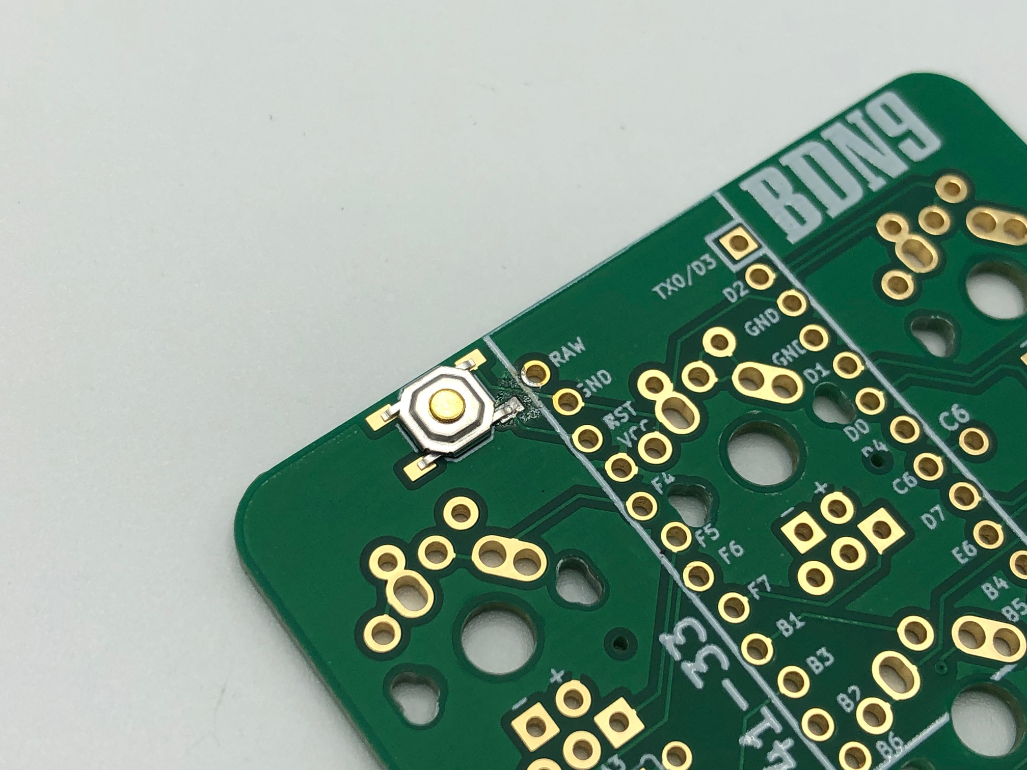
Add the reset button to the bottom side of the PCB and solder the first leg.
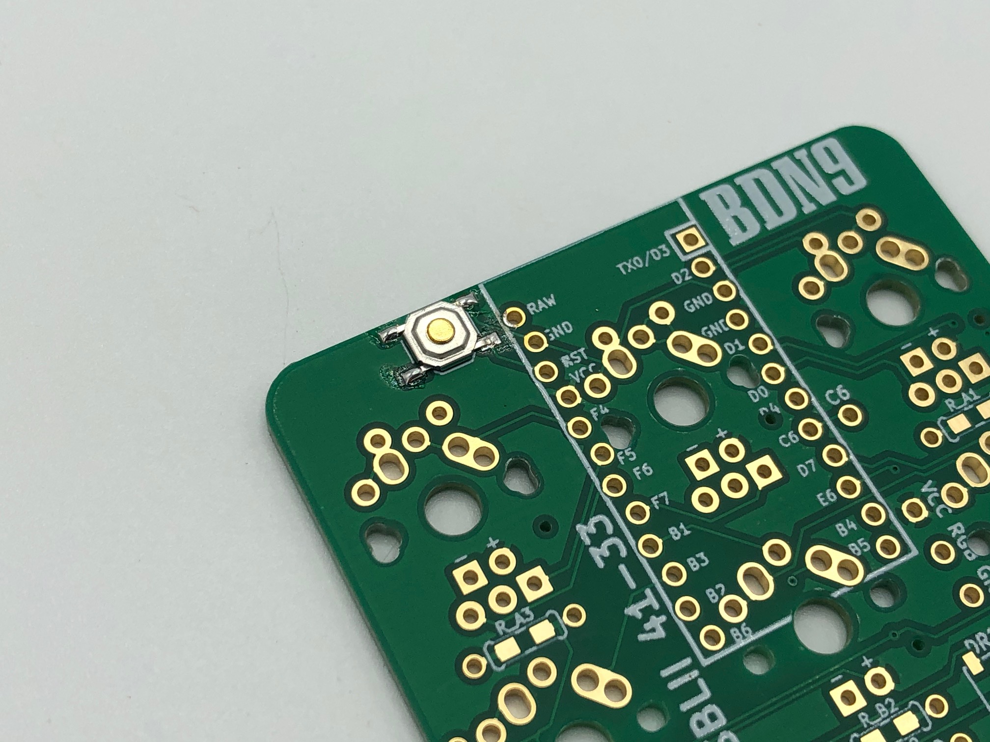
Once the first leg is aligned correctly, solder the other three legs of the reset switch.
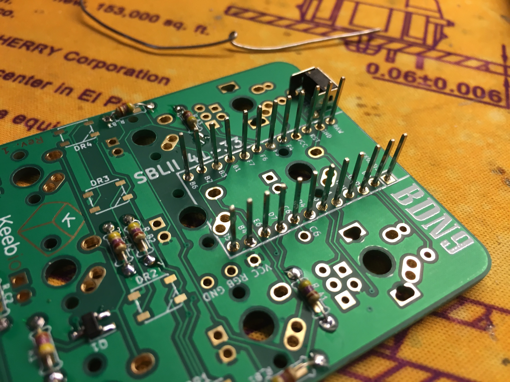
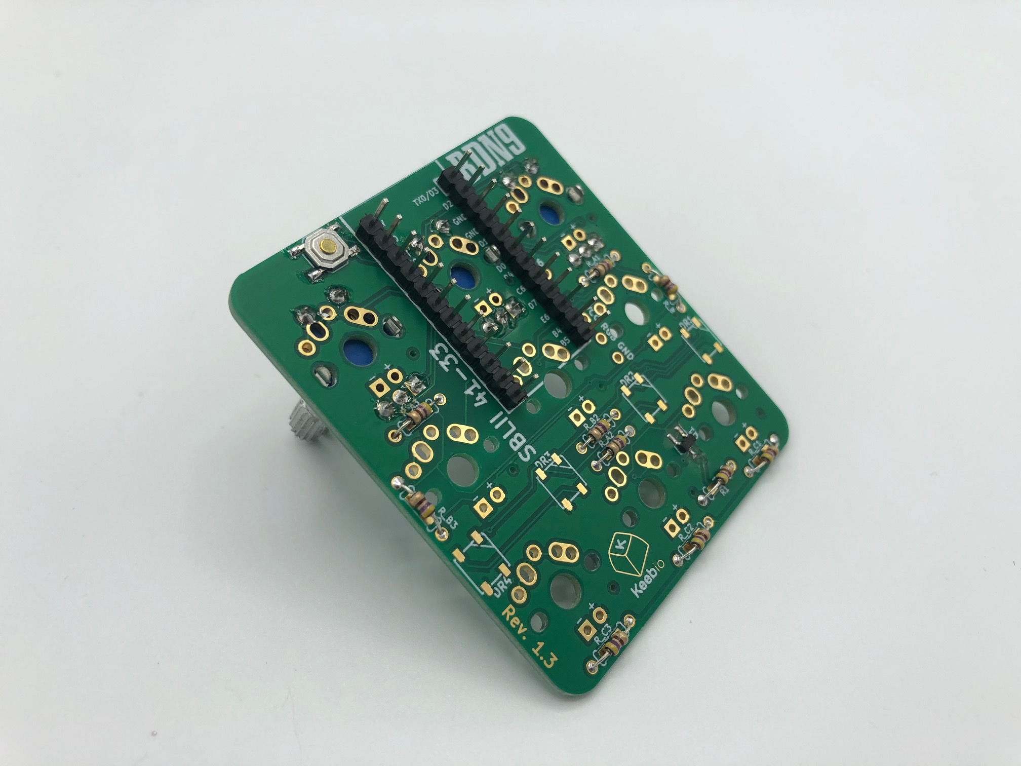
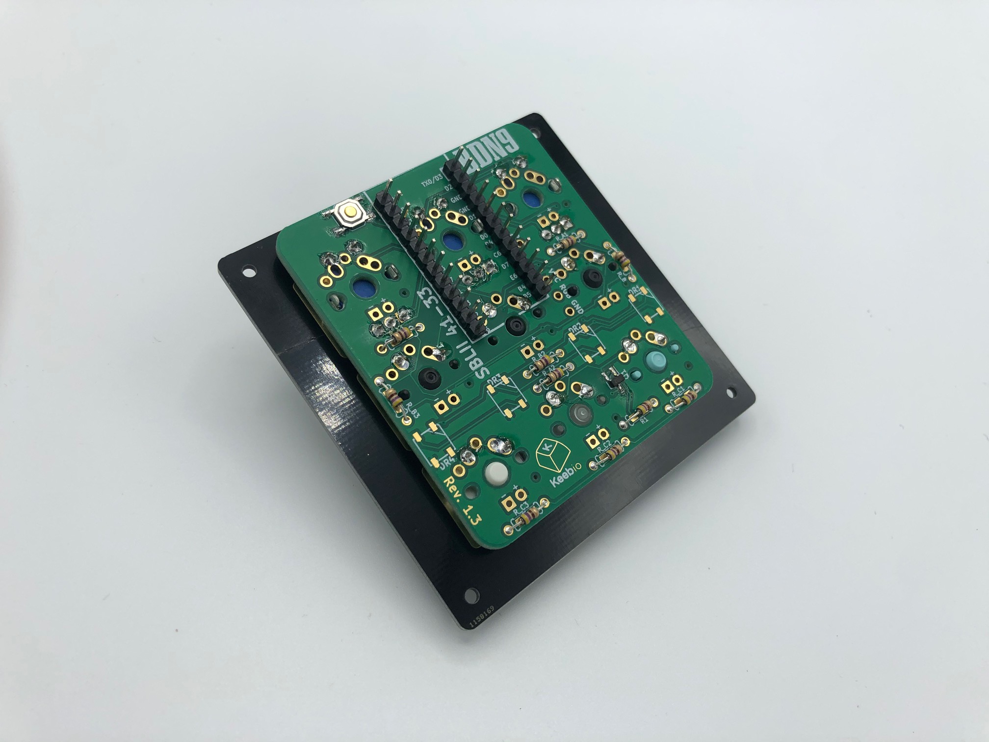
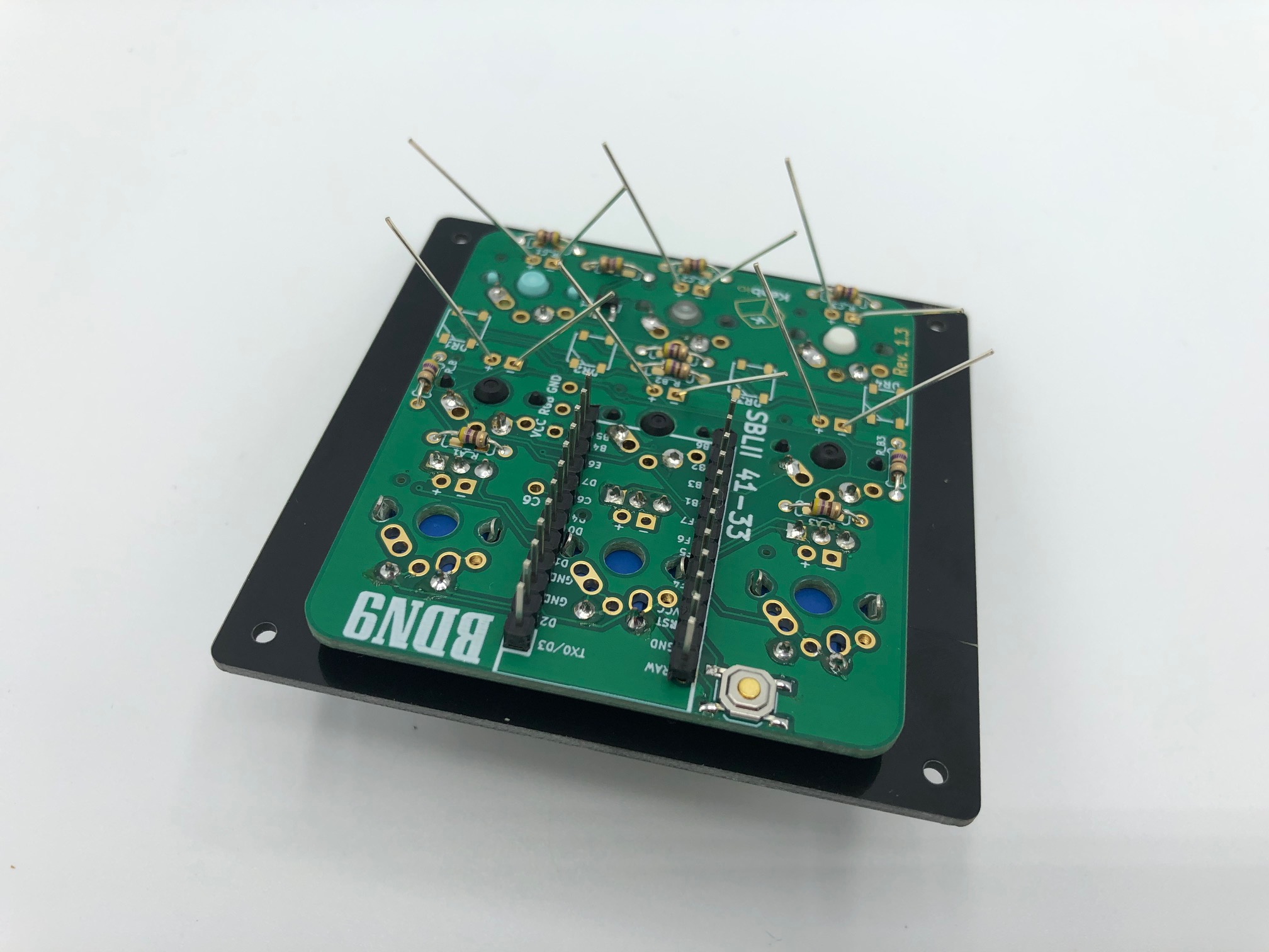
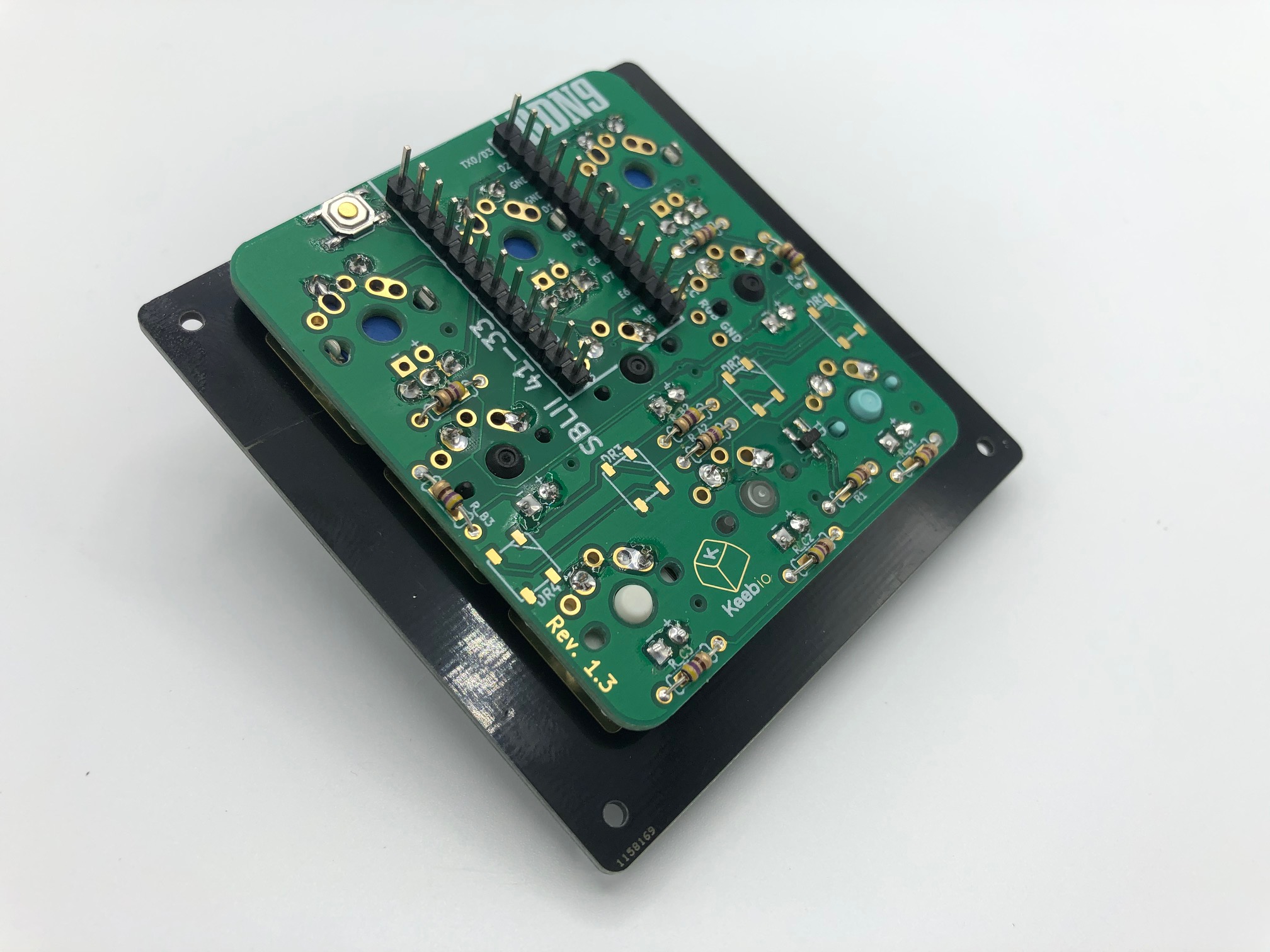
Solder Pro Micro header pins
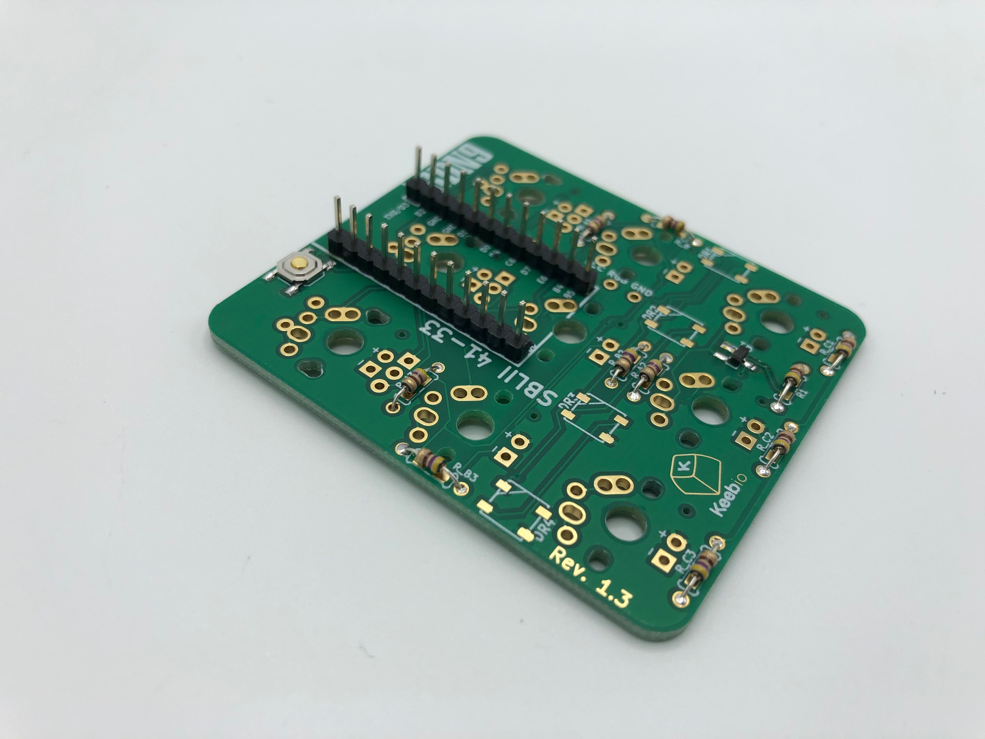
Insert the header pins into the PCB. Due to the stagger of the header pin holes, they should be able to stand up on their own once inserted. You can go with not soldering the header pins in, but it is recommended to do so anyway for a more secure fit and leaving it unsoldered is a bit more unreliable.
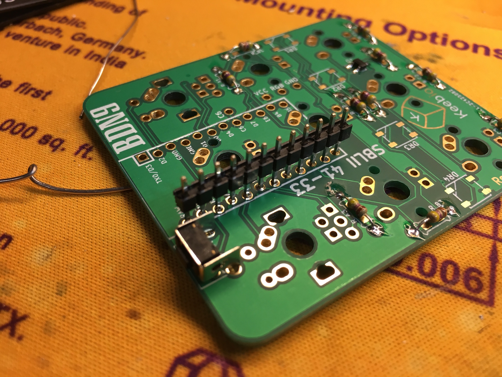
(Optional) An alternative method for soldering in the header pins is shown above. Flip the header pins upside down and solder them in. Then remove the plastic on the header pins by prying it off. The benefit of doing this method is that the Pro Micro Micro-USB port will be flush against the PCB, which helps from getting it ripped off.
Solder the header pins to the PCB.
(Optional) Remove plastic from header pins
Solder Rotary Encoders
Rotary encoders must be soldered on before switches are added
It is difficult to put in the rotary encoders into the PCB pads if the switch plate and switches are already on, so make sure you add the encoders first.
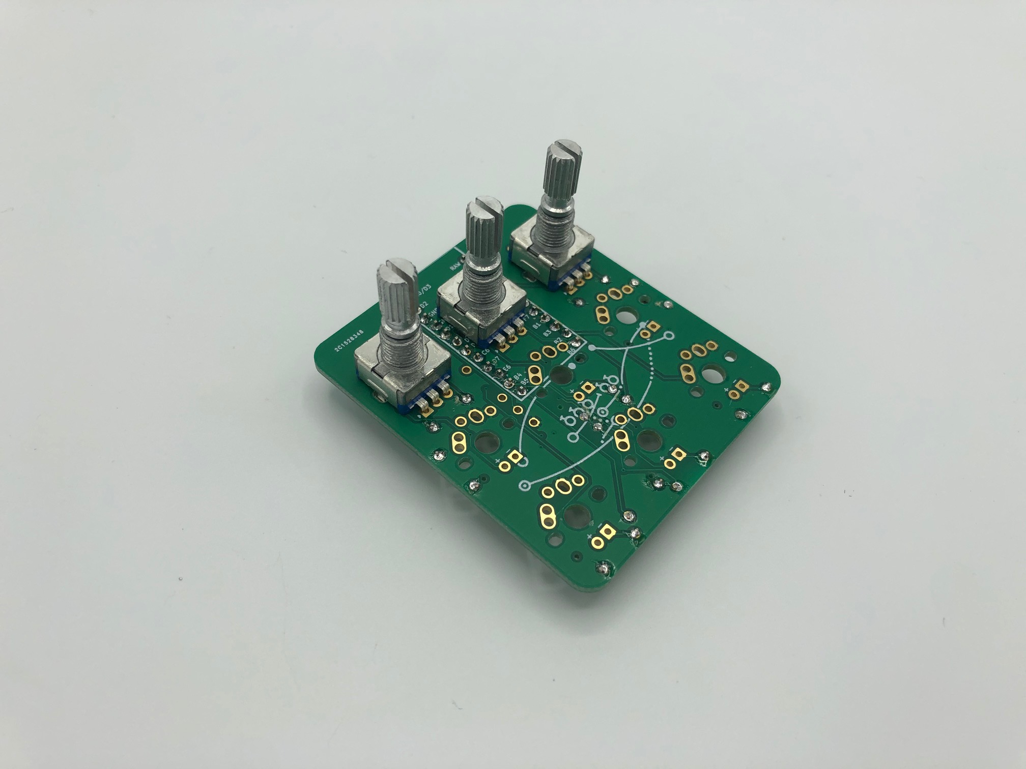
Insert the rotary encoders from the top-side of the PCB.
Solder the rotary encoders in.
If using Choc low-profile switches, double check/add Kapton tape to solder/metal connections on top of the PCB
When using Choc low-profile switches, there is very little clearance between the switch plate and the top of the PCB. Any exposed metal/solder can cause a short if it touches the switch plate, so before you add the switches to the plate and solder them to the PCB, it's advised that you double check that all solder joints on the top of the PCB are cut flush. Alternatively, you can add Kapton tape to any that are raised. It doesn't hurt to add Kapton tape to the encoder legs as well.
Solder Switches
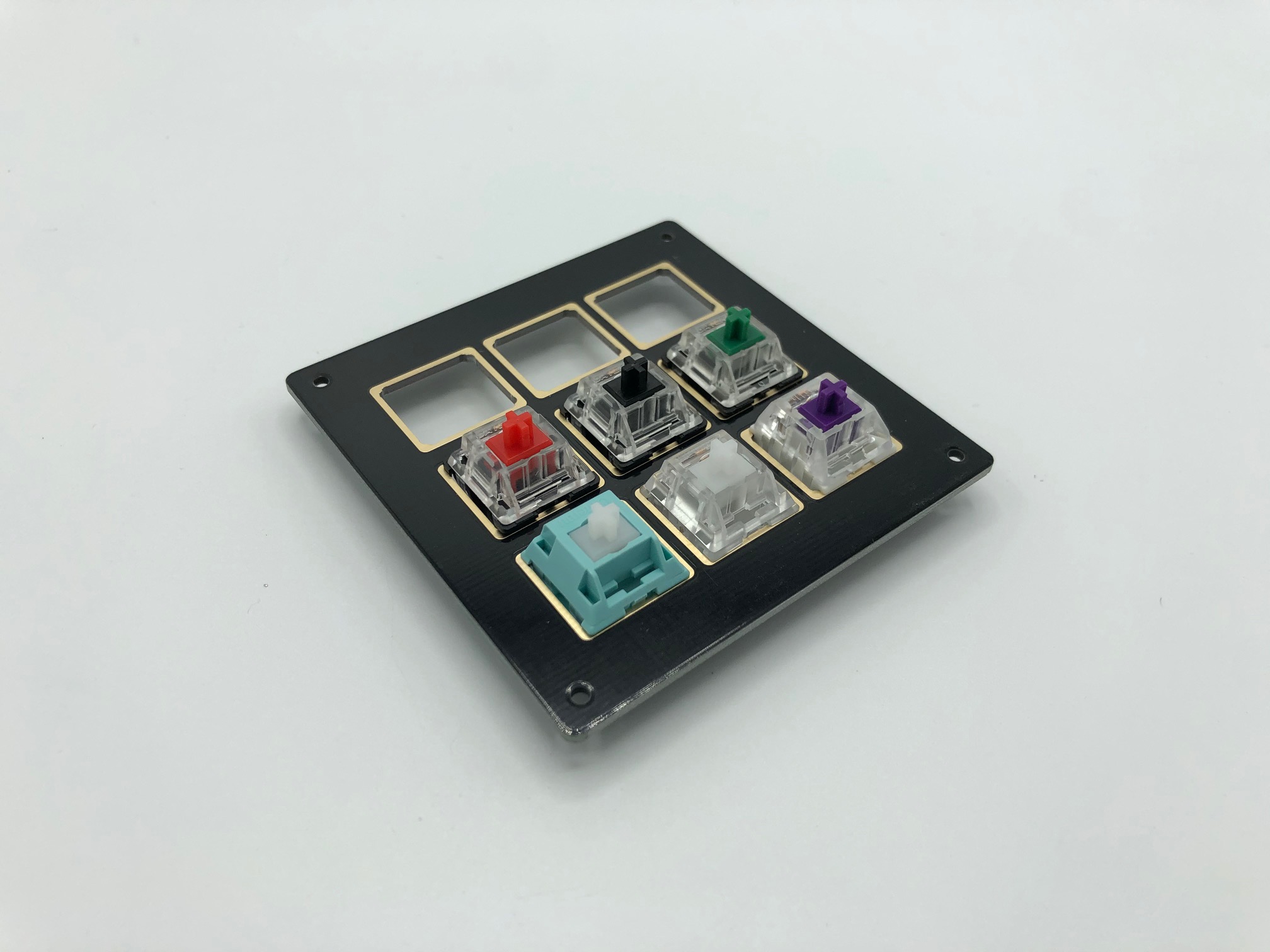
Add the switches to the switch plate.
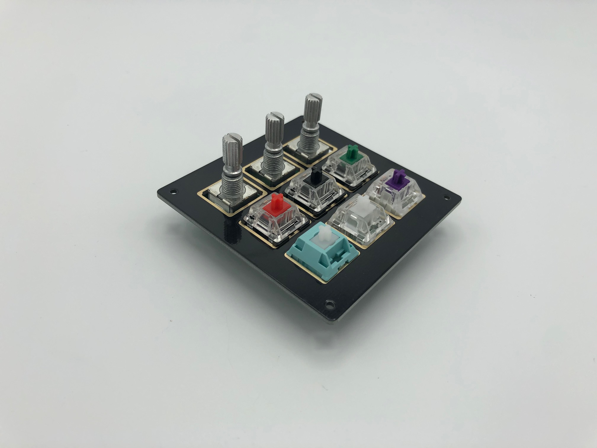
Then, place it on top of the PCB and make sure all the switches are seated firmly into the PCB.
Solder the switches onto the PCB.
Solder LEDs (optional)
Add LEDs through the switch. The longer leg of the LED (anode) should go through the circular pad, while the shorter leg (cathode) goes through the square pad.
Bend the legs of the LEDs outwards a bit to hold them in place.
Solder the the LEDs in. Then clip the legs down.
Flash Pro Micro
See Flashing Firmware for instructions on flashing the Pro Micro if you are unfamiliar with this step.
Prepare and solder the Pro Micro
Clip the switch legs and plastic pieces of the 2 switches that sit on top of the Pro Micro, so they don't interfere with the Pro Micro.
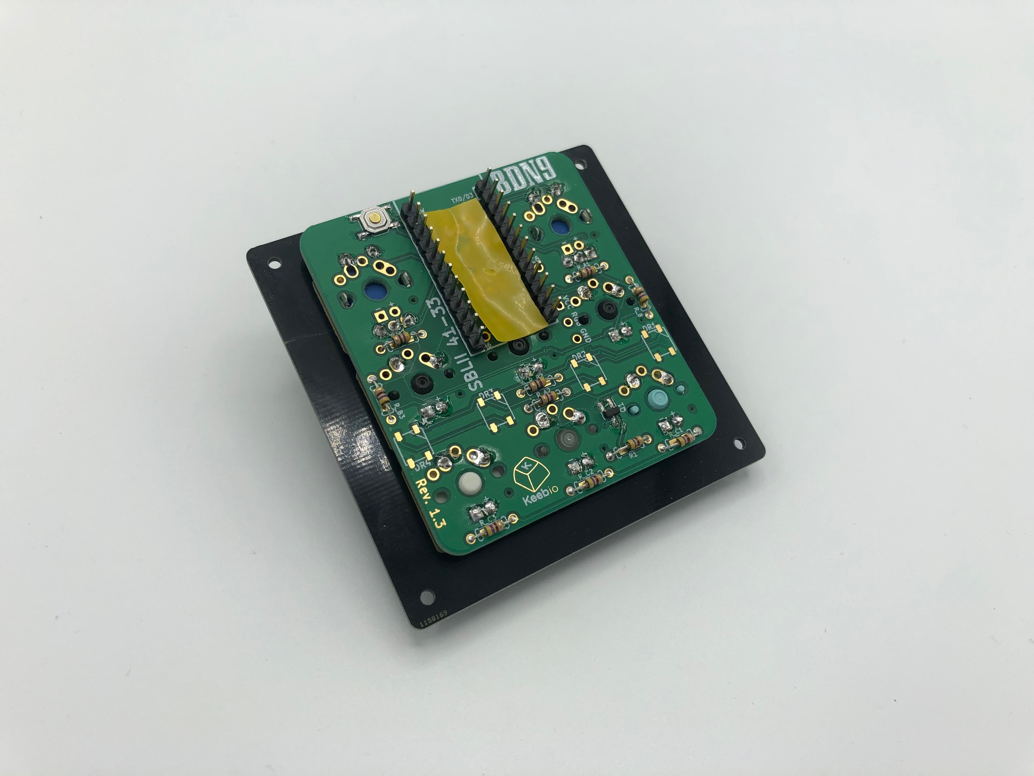
Then put some electrical or Kapton tape on top of the area the Pro Micro will be.
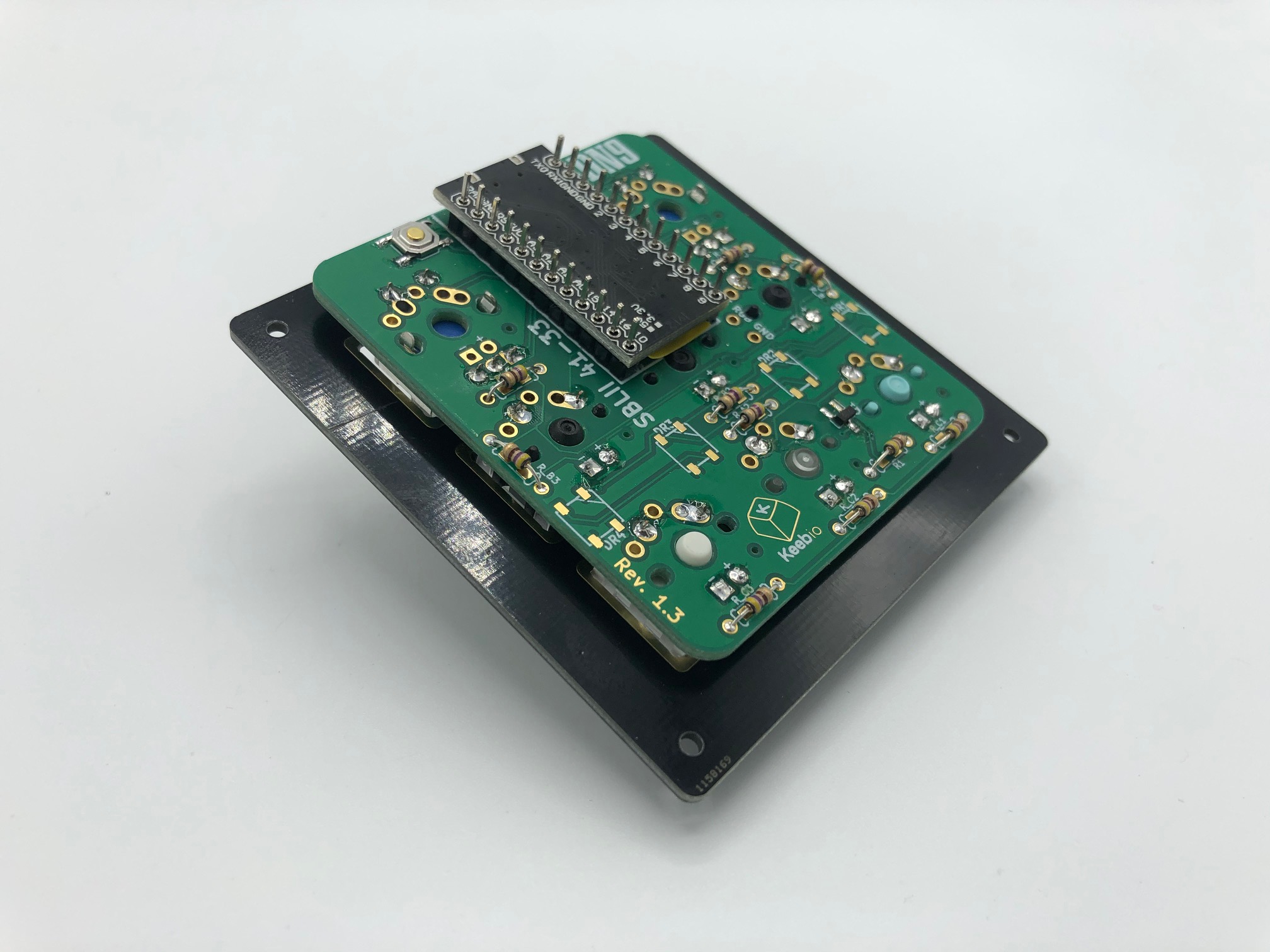
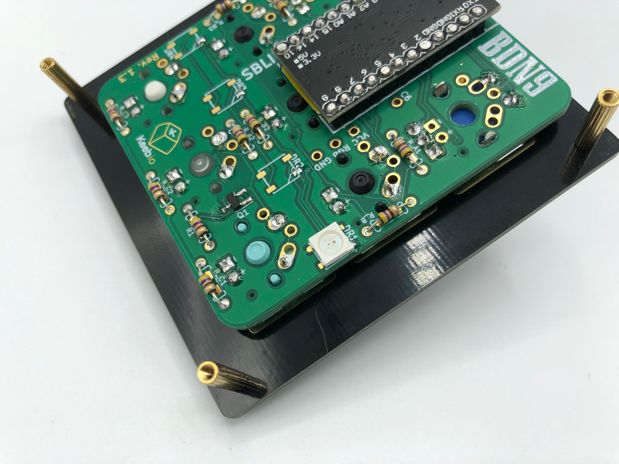
Insert Pro Micro over the header pins.
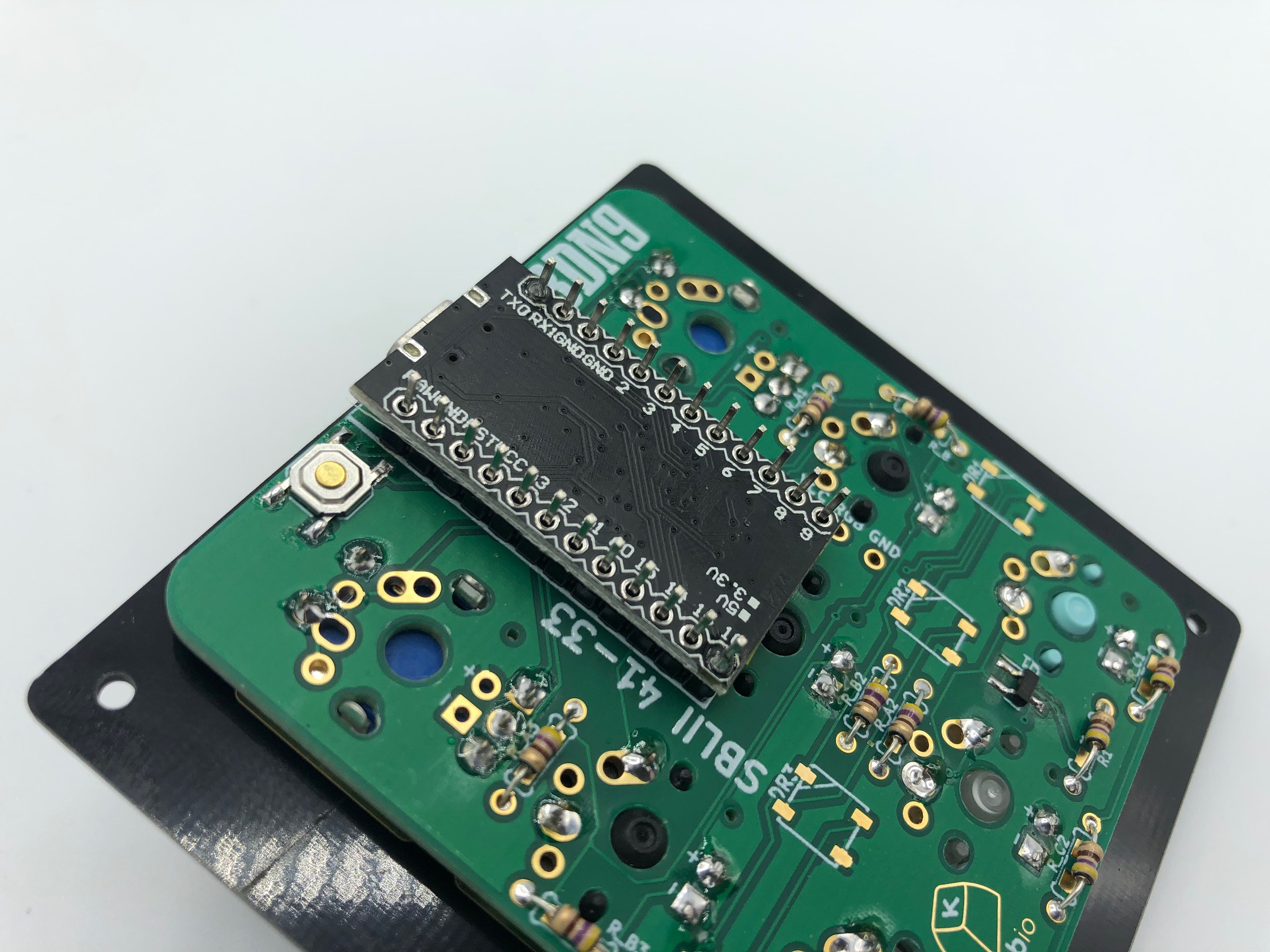
Add solder to two opposite corners of the Pro Micro and make sure the controller is aligned properly and is level.
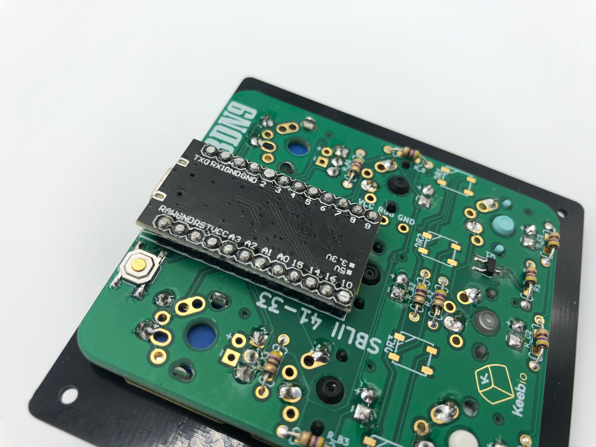
Solder the reset of the pins and clip the legs off.
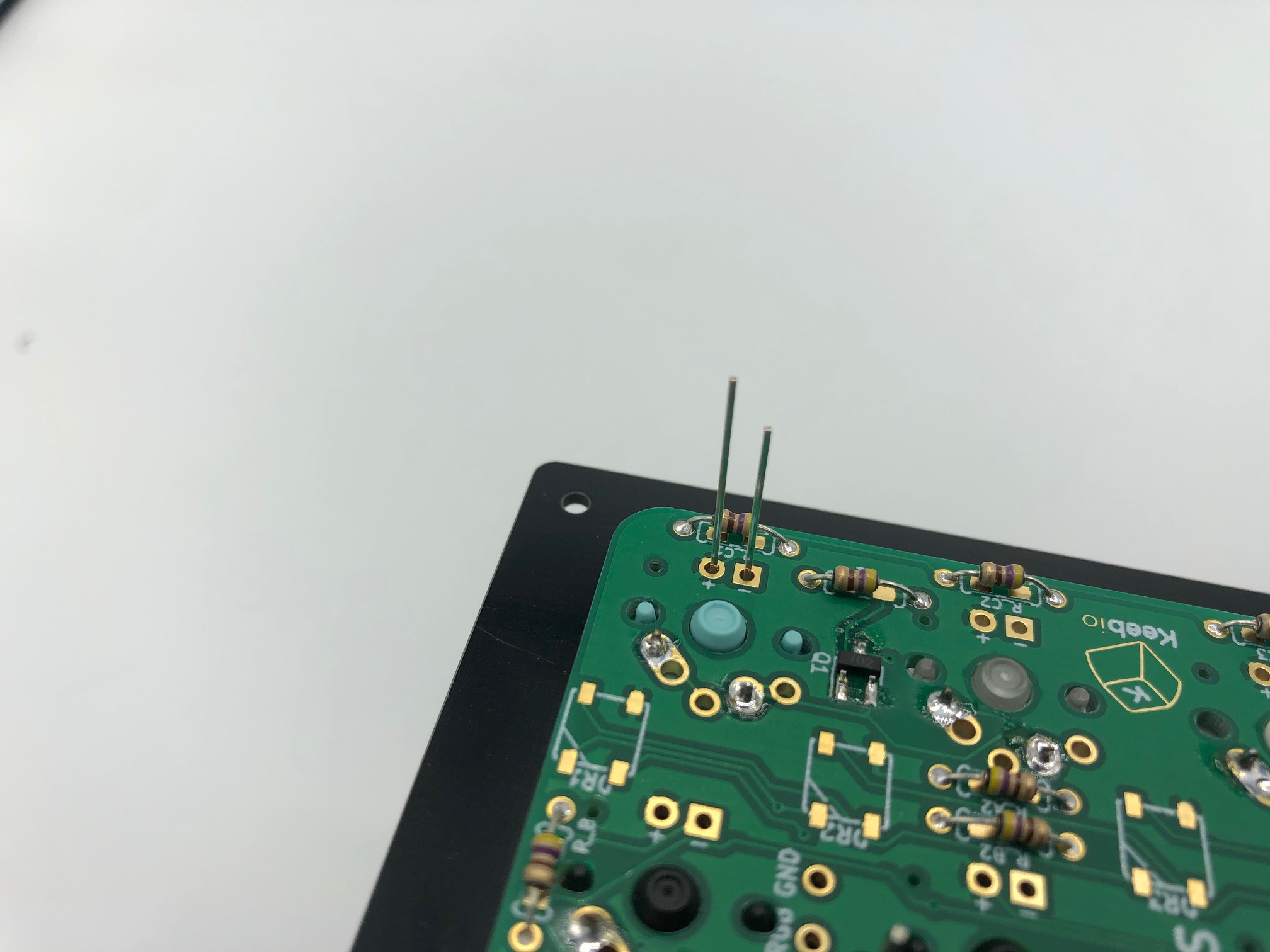
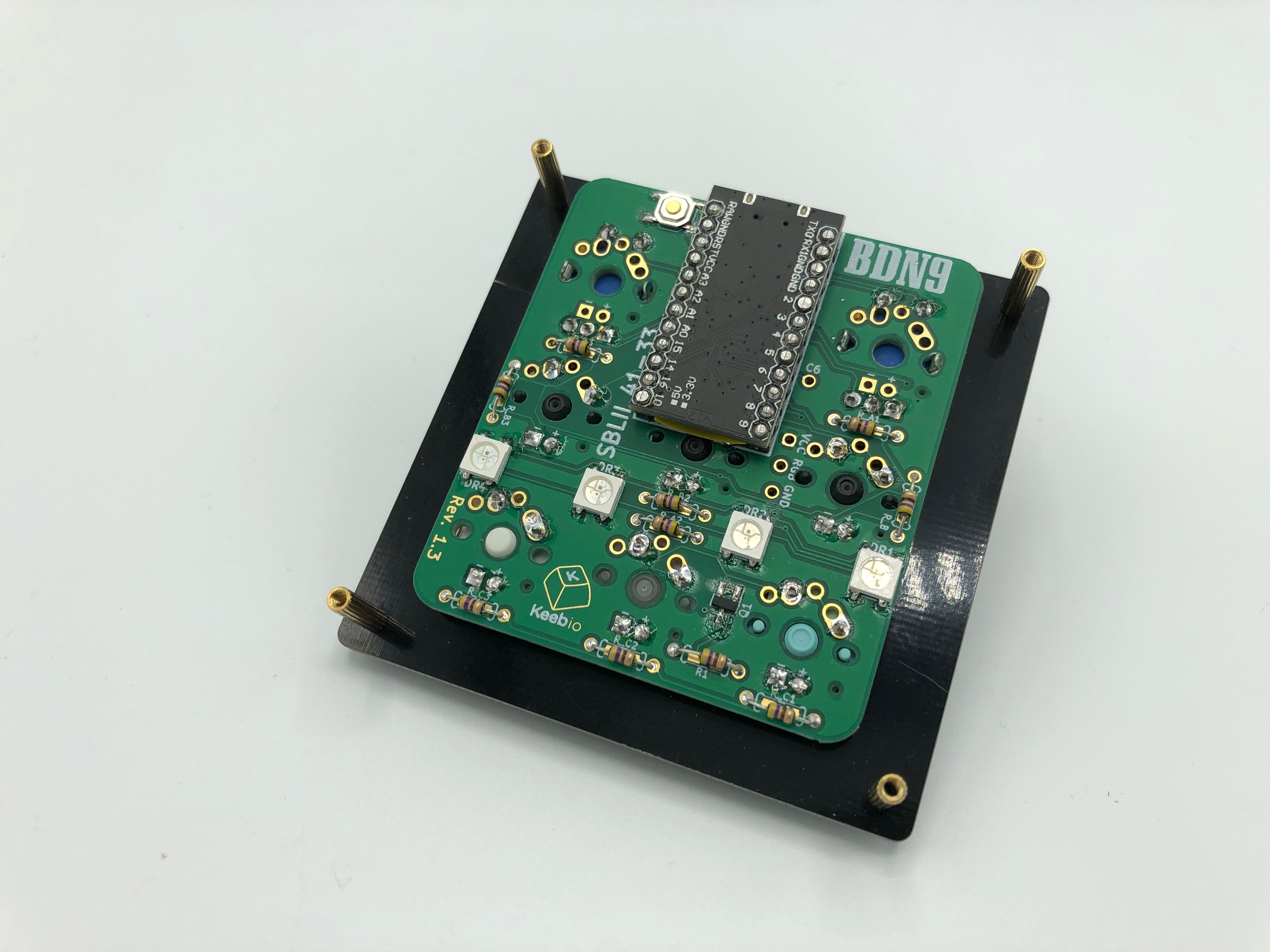
Solder RGB underglow LEDs or strip (optional)
RGB LED pads
The BDN9 Rev. 1.0 only has three breakout pads (RGB, GND, and VCC) to solder an RGB LED strip to.
The BDN9 Rev. 1.1 has RGB LED pads add another option for adding RGB underglow. Only strips or individual LEDs can be added to this boards (don't do both at the same time).
Add RGB LED Strip (optional)
If using an RGB LED strip, see the Adding RGB Underglow guide.
Add individual RGB LEDs (optional)
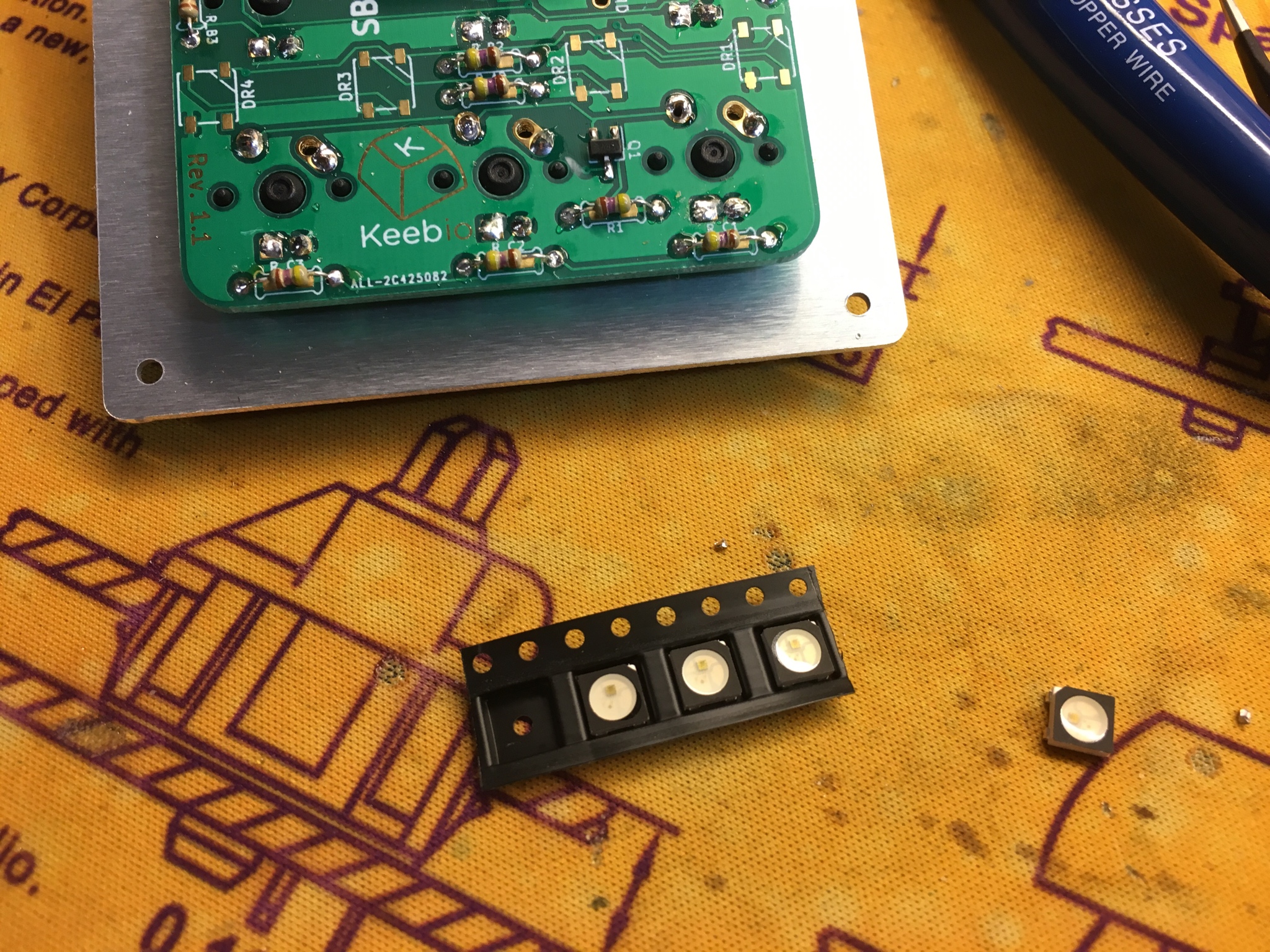
WS2812B or SK6812 RGB LEDs can be added individually to the board.
Add solder to one pad of each LED footprint.
Using a pair of tweezers, hold each LED in place and solder it in.
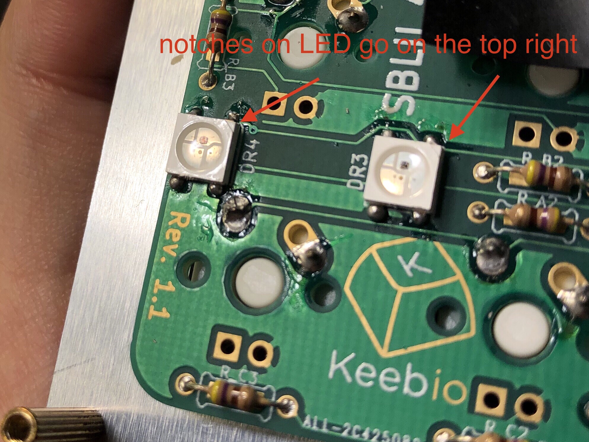
Note: Before soldering ensure each LED is properly aligned, with the corner notch on the top-right pad.
Once the LEDs are aligned properly, solder the other 3 pads. Make sure each pad of the LED has enough solder on it.
Assemble Case
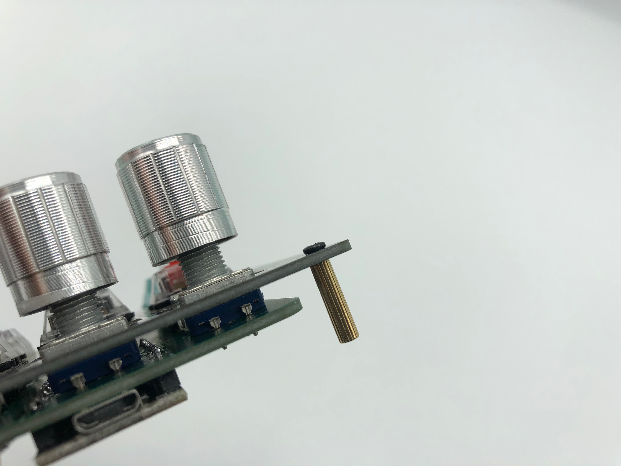
Screw in the standoffs to the switch plate at all four corners.
Add the bottom plate and screw it in.
Plug it in and test. For the RGB underglow, the mode is controlled by the right-most key in the middle row. If the RGB LEDs don't light up, check your wiring or make sure the pads have enough solder.