Fourier
Parts List
Here's a list of parts needed for the build:
- 2 Reset Switches (included in kit)
- 2 4.7kΩ resistors (included in kit)
- 2 TRRS Jacks (included in kit)
- 47 1N4148 diodes - through hole (included in kit) and SMD diodes supported
- 28 M2 6mm screws (included with plates)
- 14 M2 10mm standoffs (included with plates)
1 Micro USB Cable
MX or Alps compatible keyswitches
WS2812B Compatible RGB LED strip (optional, for underglow)
Build Steps
- Prepare components
- Solder components
- Solder diodes
- Solder push button
- Solder 4.7kΩ resistors (optional)
- Solder Pro Micro header pins
- Solder switches
- Flash Pro Micro
- Solder Pro Micro
- Solder RGB strip (optional)
Prepare Components
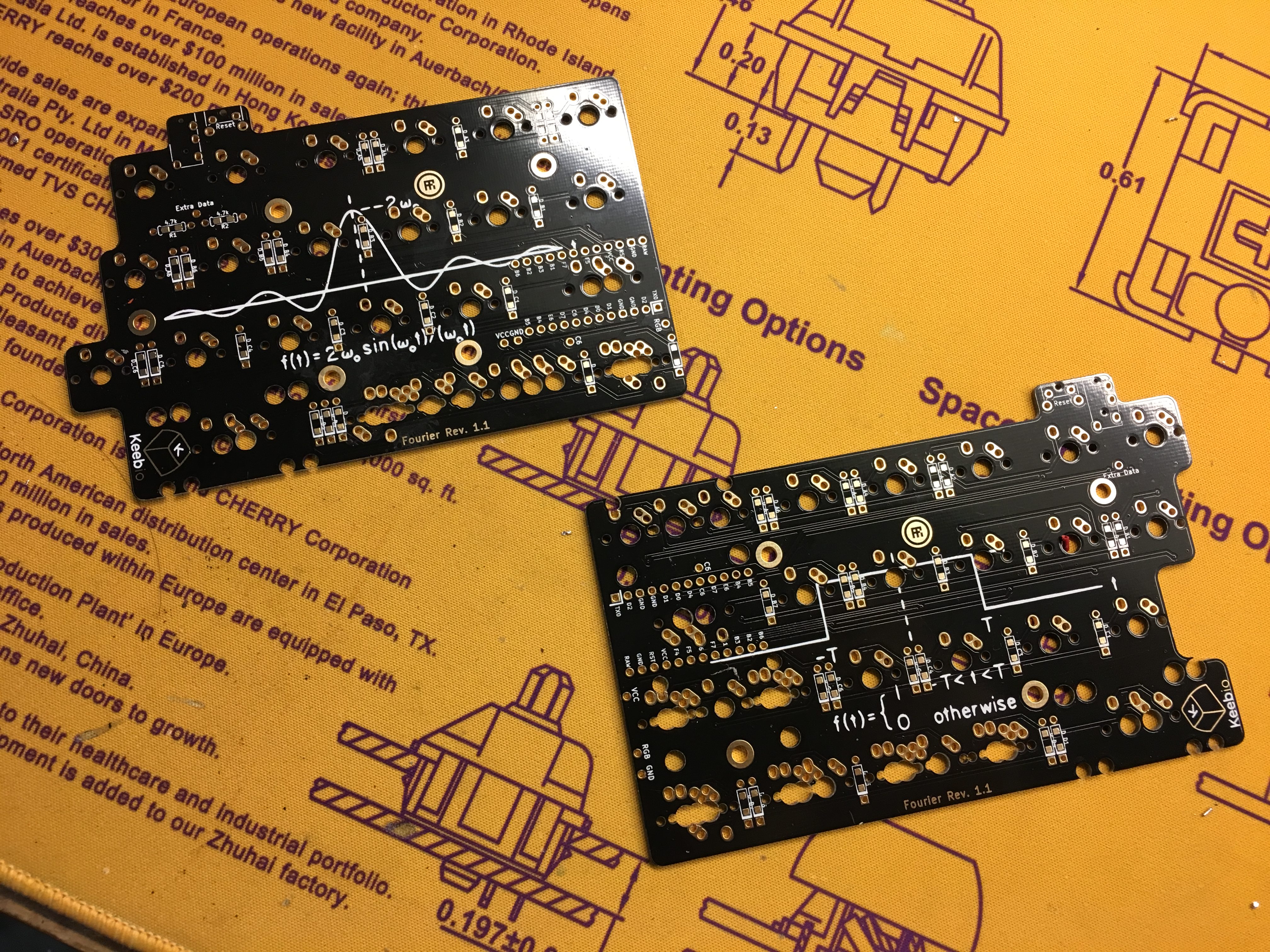
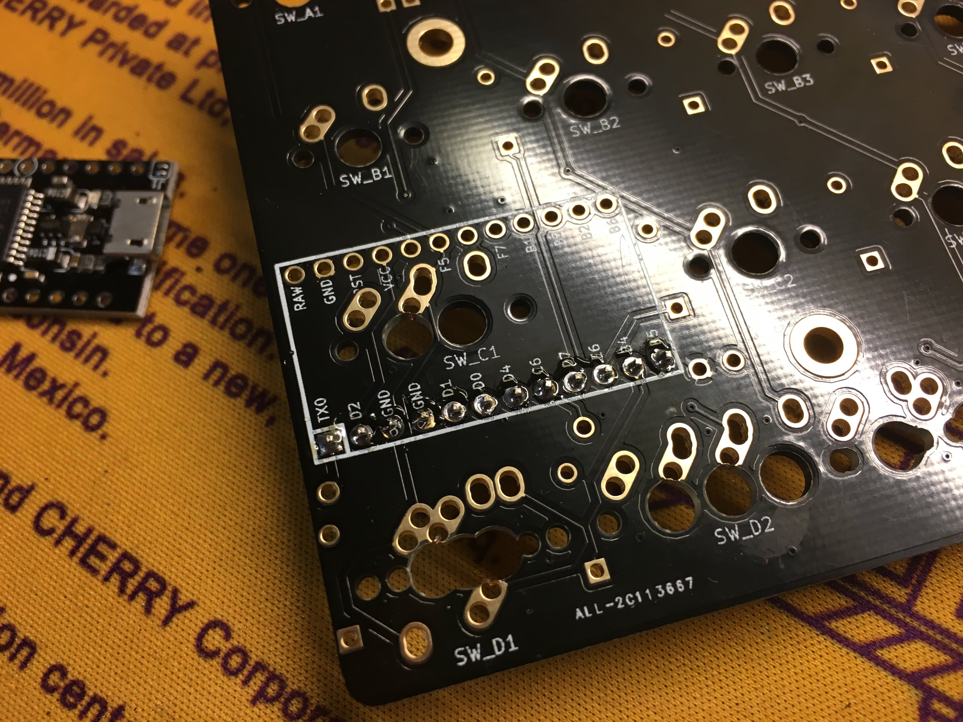
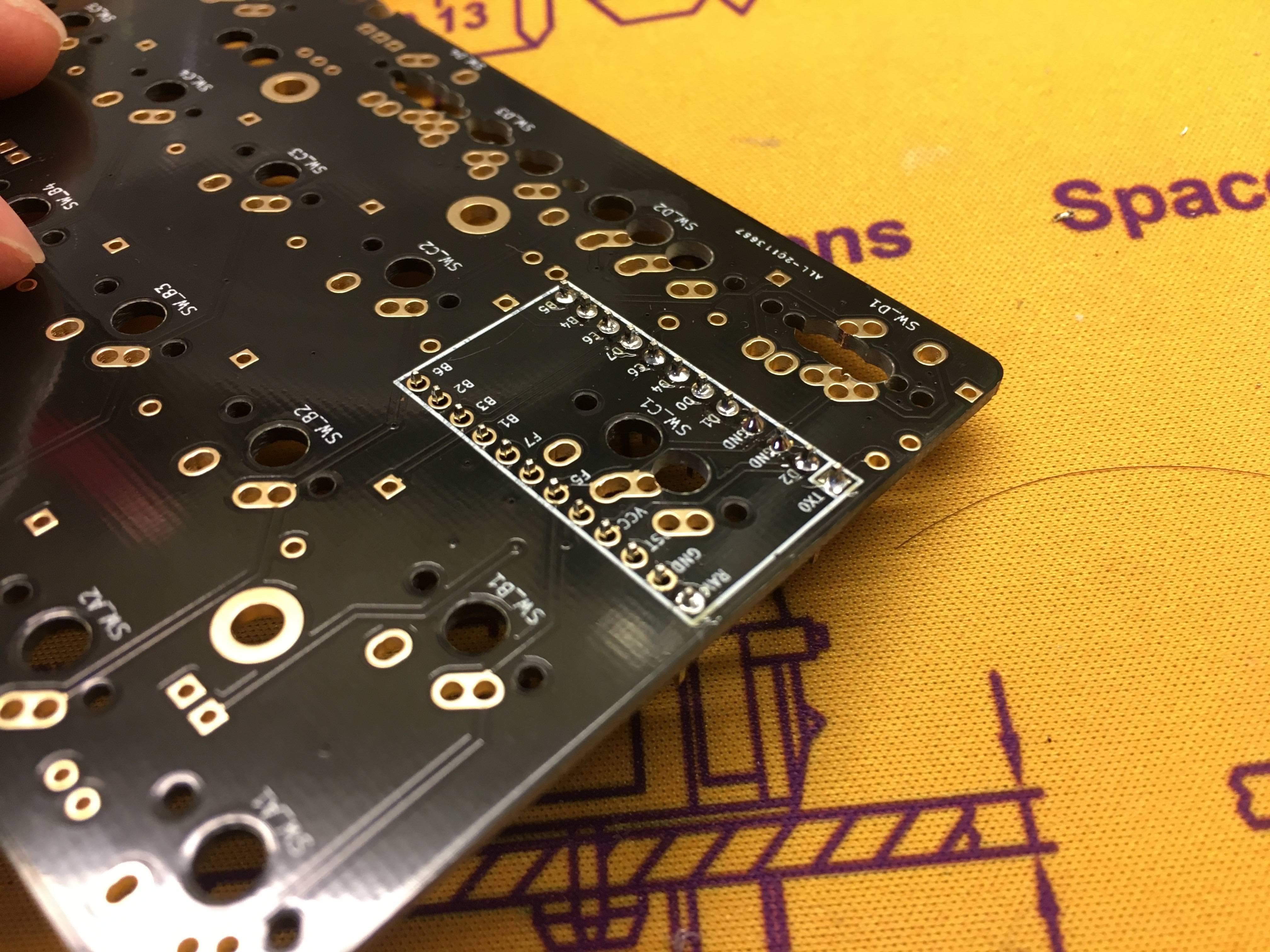
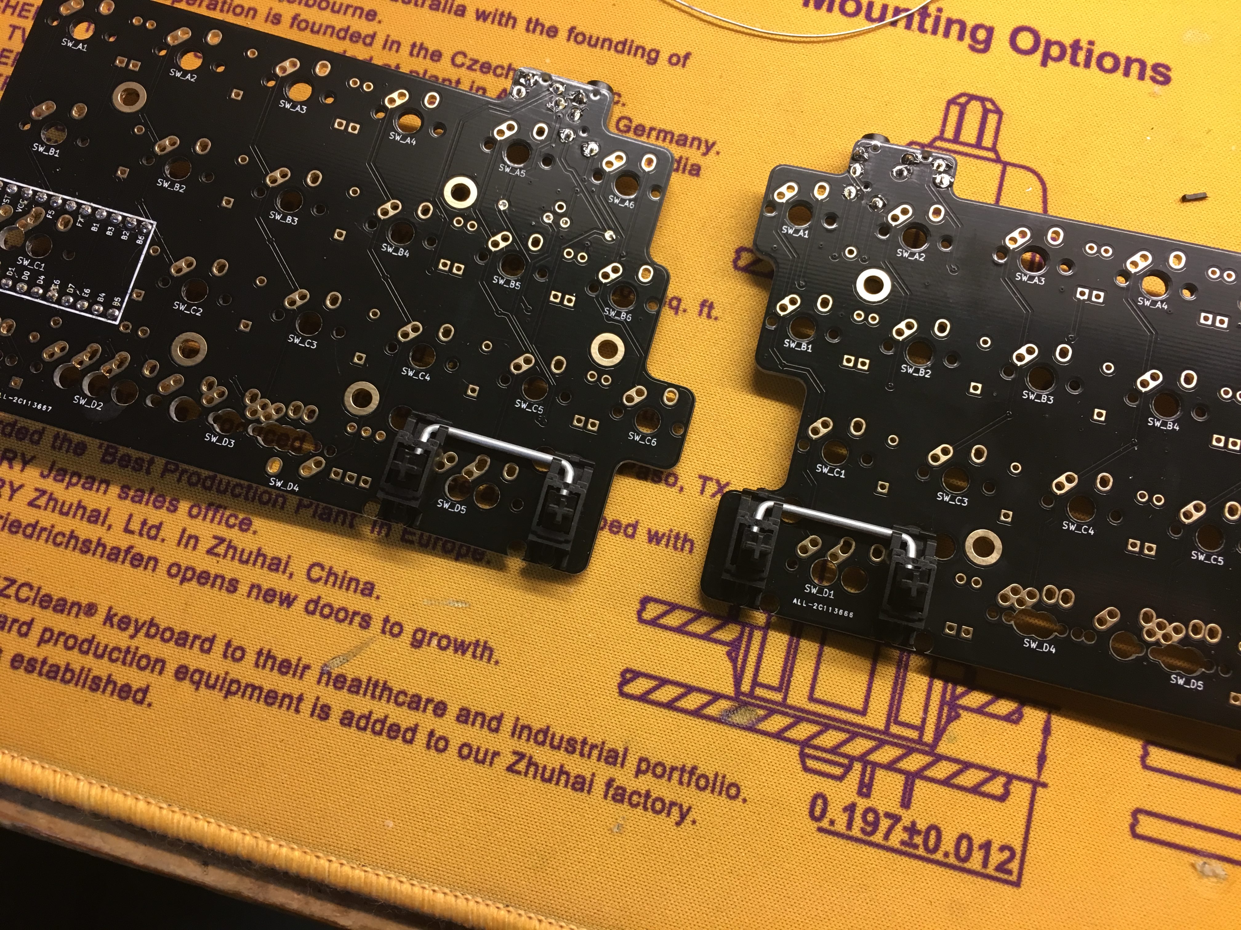
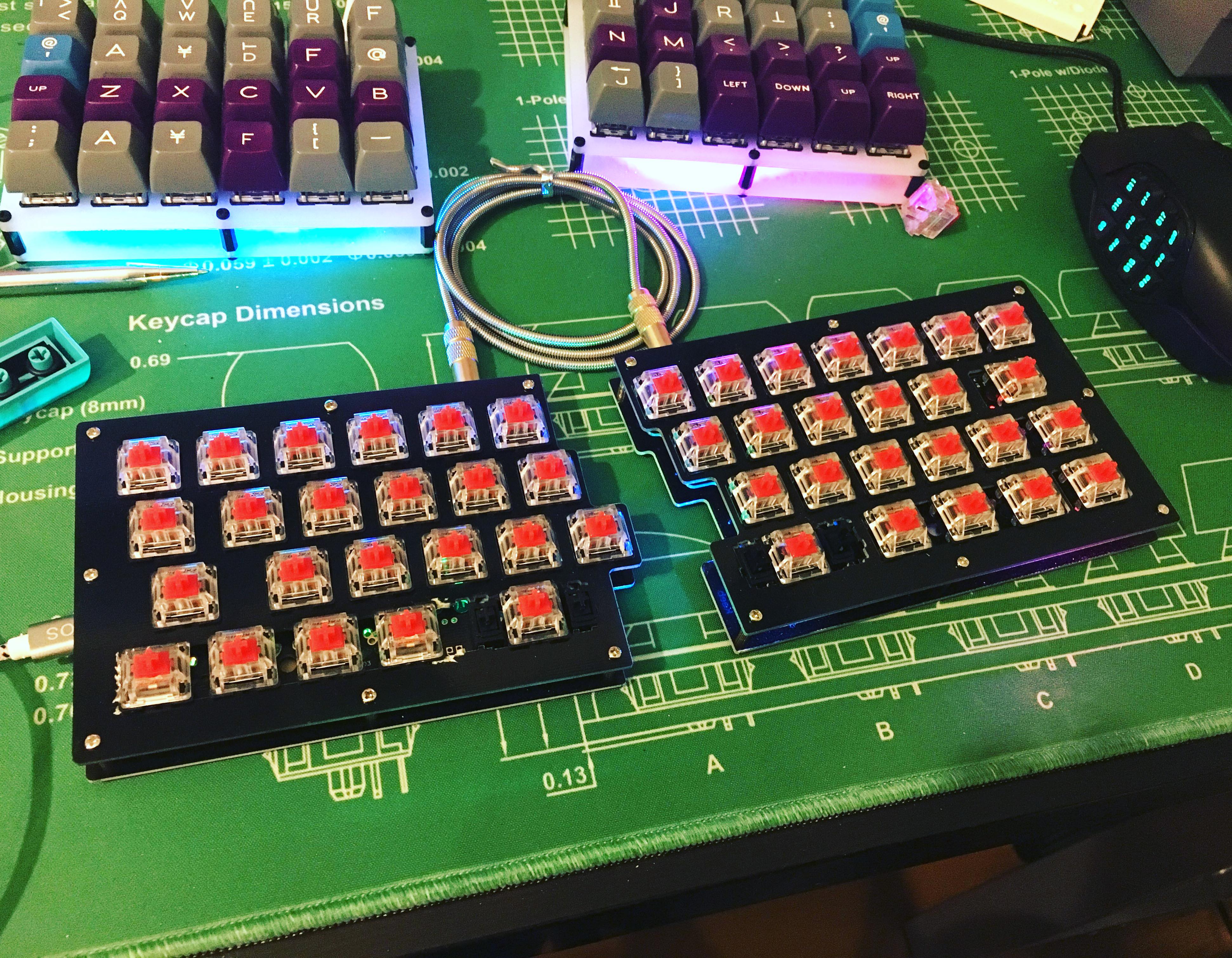
Grab your PCBs. Pictured bottoms up -- left is on the left, right is on the right.
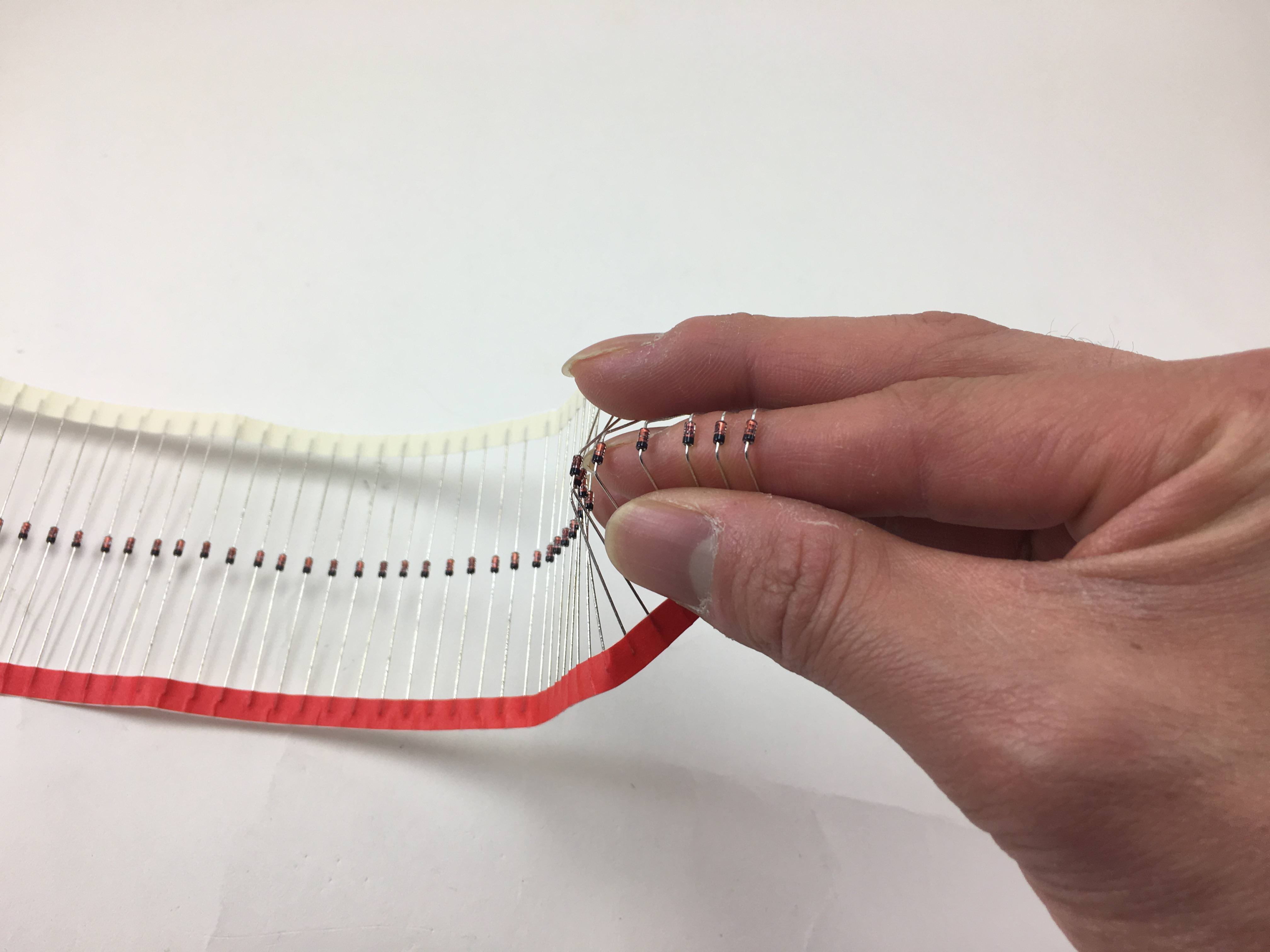
If you're using through hole diodes, bend 'em up. Here, I'm just bending it around my finger
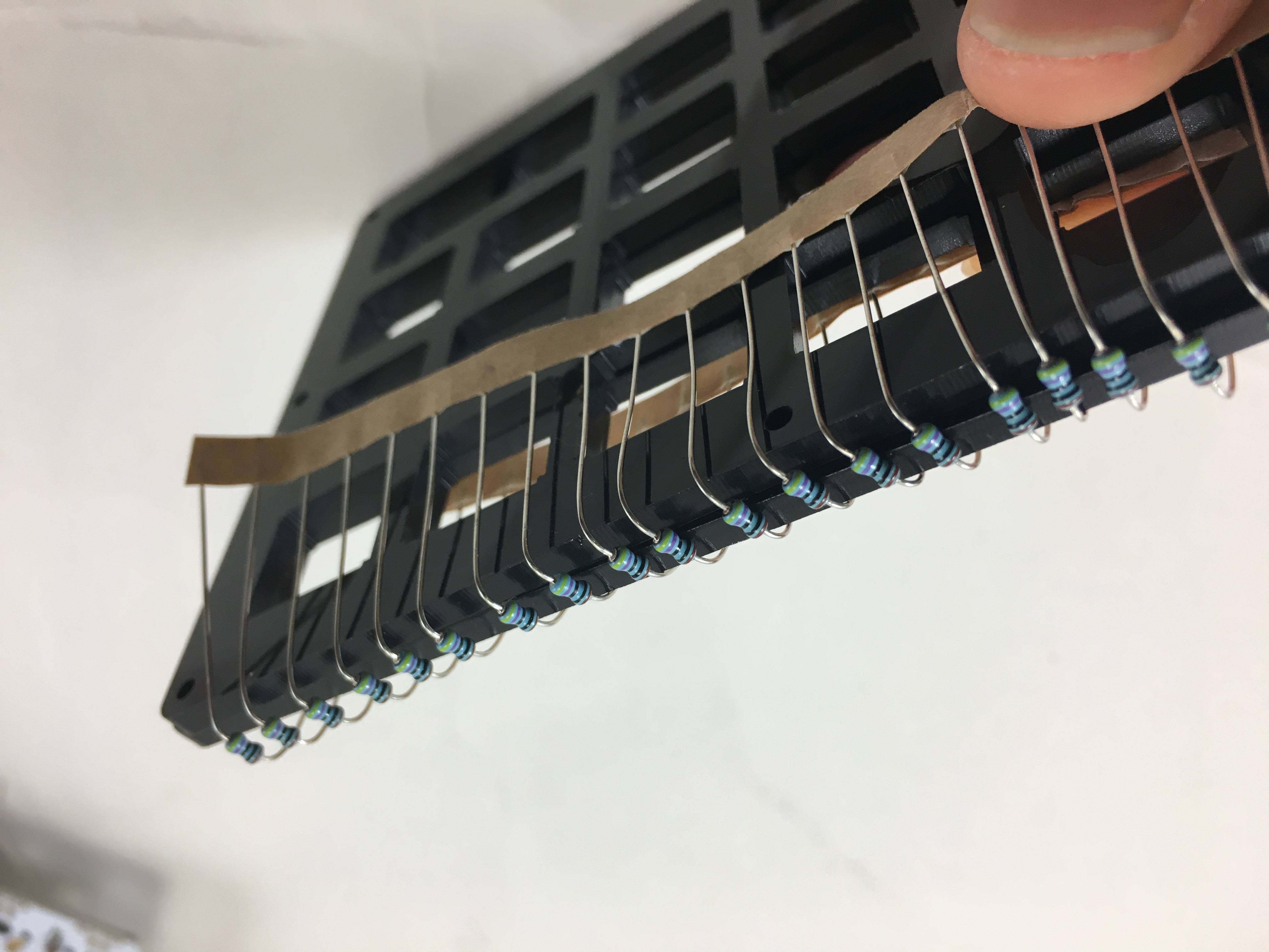
Another way to do it, resistors shown here
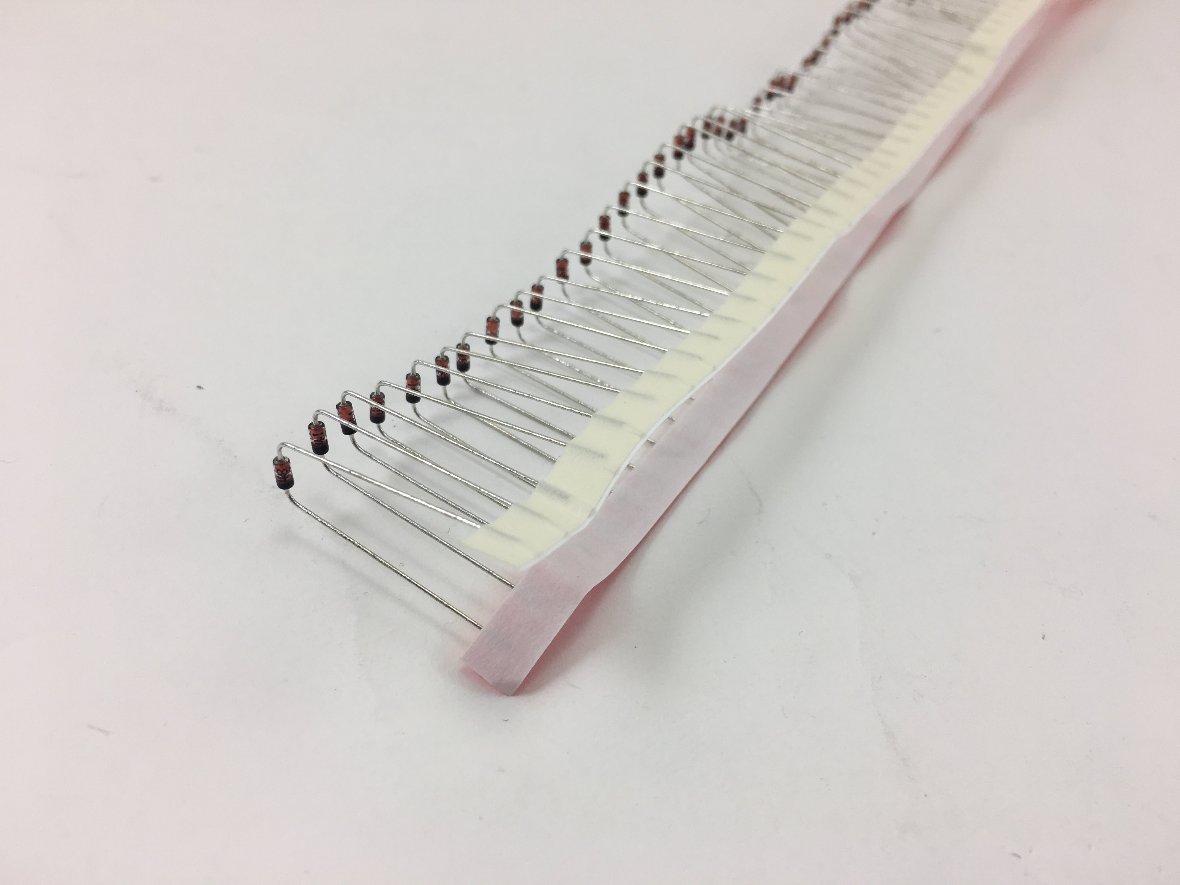
Strip of diodes bent
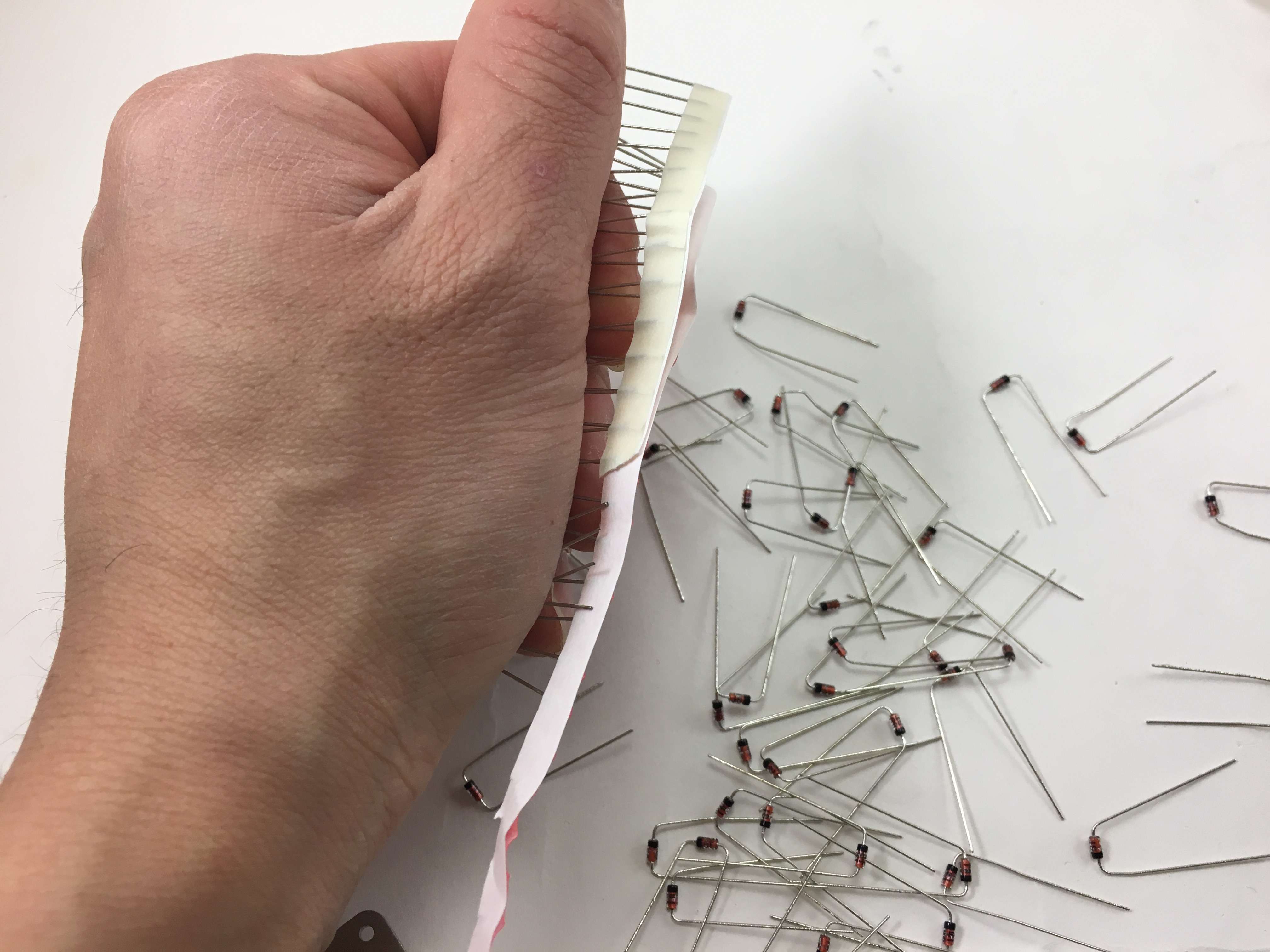
Ripping off the paper holding all the resistors together. Grip the diodes tightly so they don't bend as you're ripping the paper off.
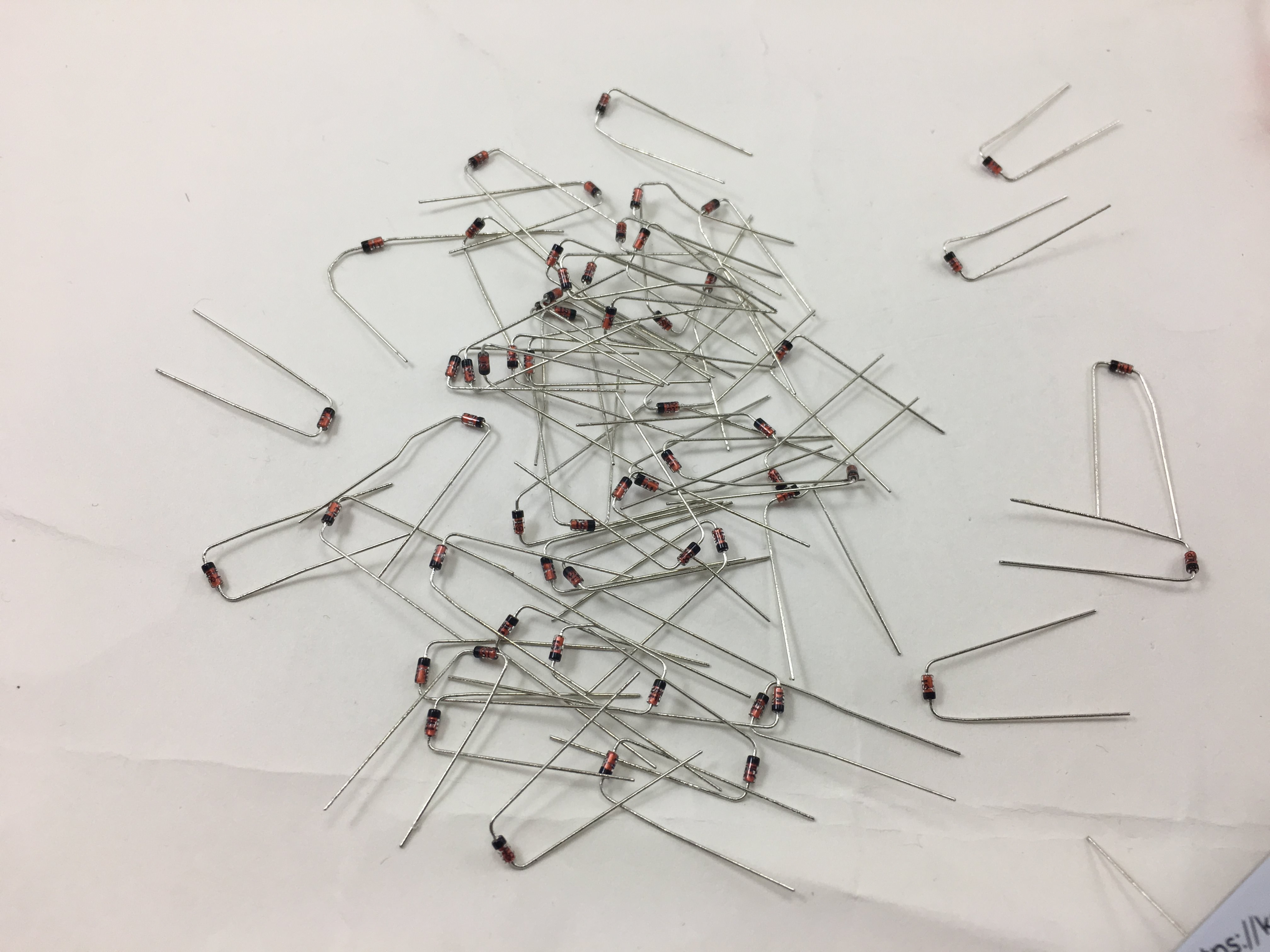
All separated from the paper
Solder Components
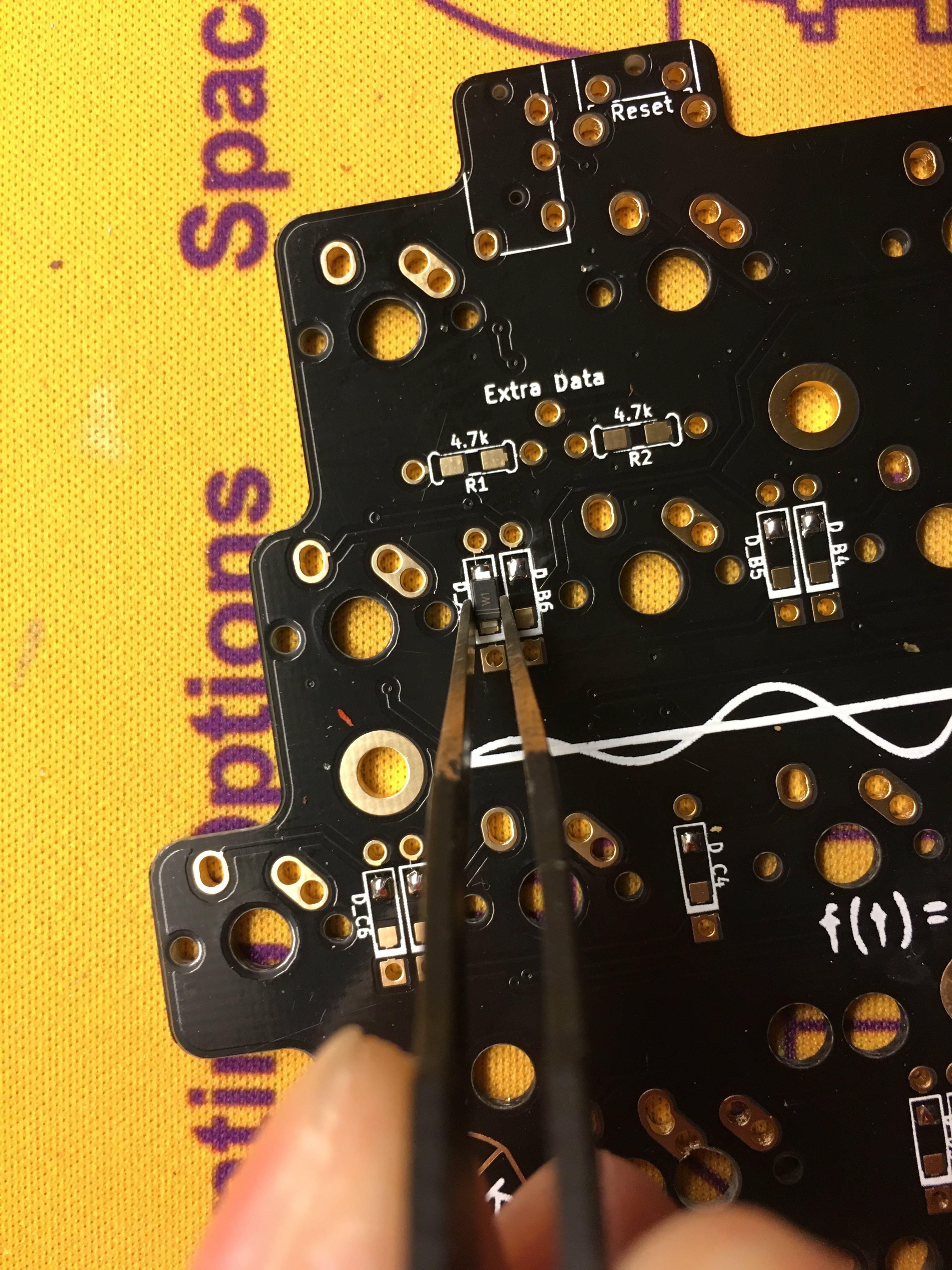
Install the diodes. SMD diodes are being used here, since they're a lot faster for me to install. The orientation of all the diodes are the same, they are vertically oriented, with the band on the diodes facing towards the bottom, square pad.
SMD diodes have a white band as shown in this picture, through-hole diodes will have a black band.
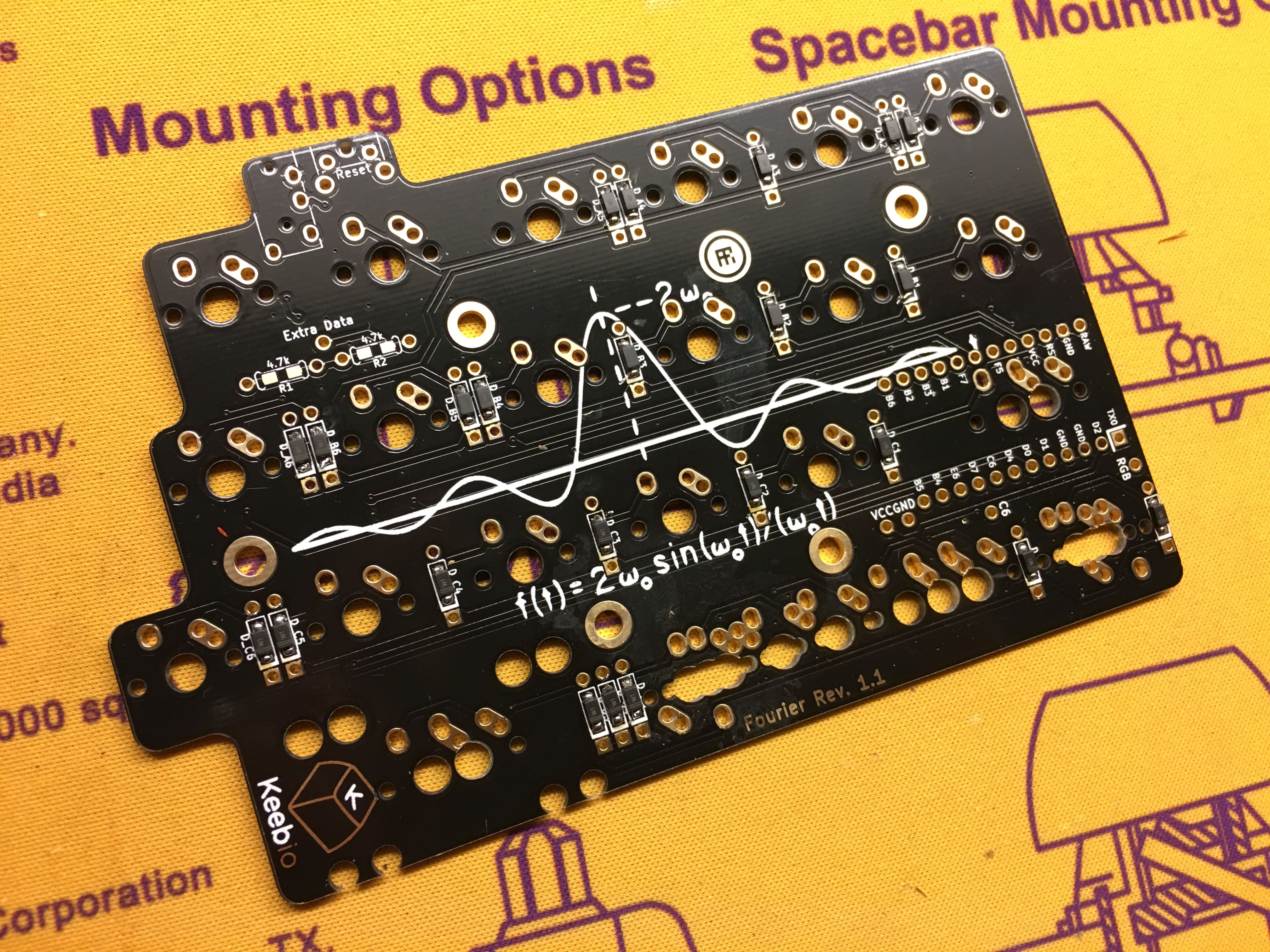
All the diodes installed on the left PCB.
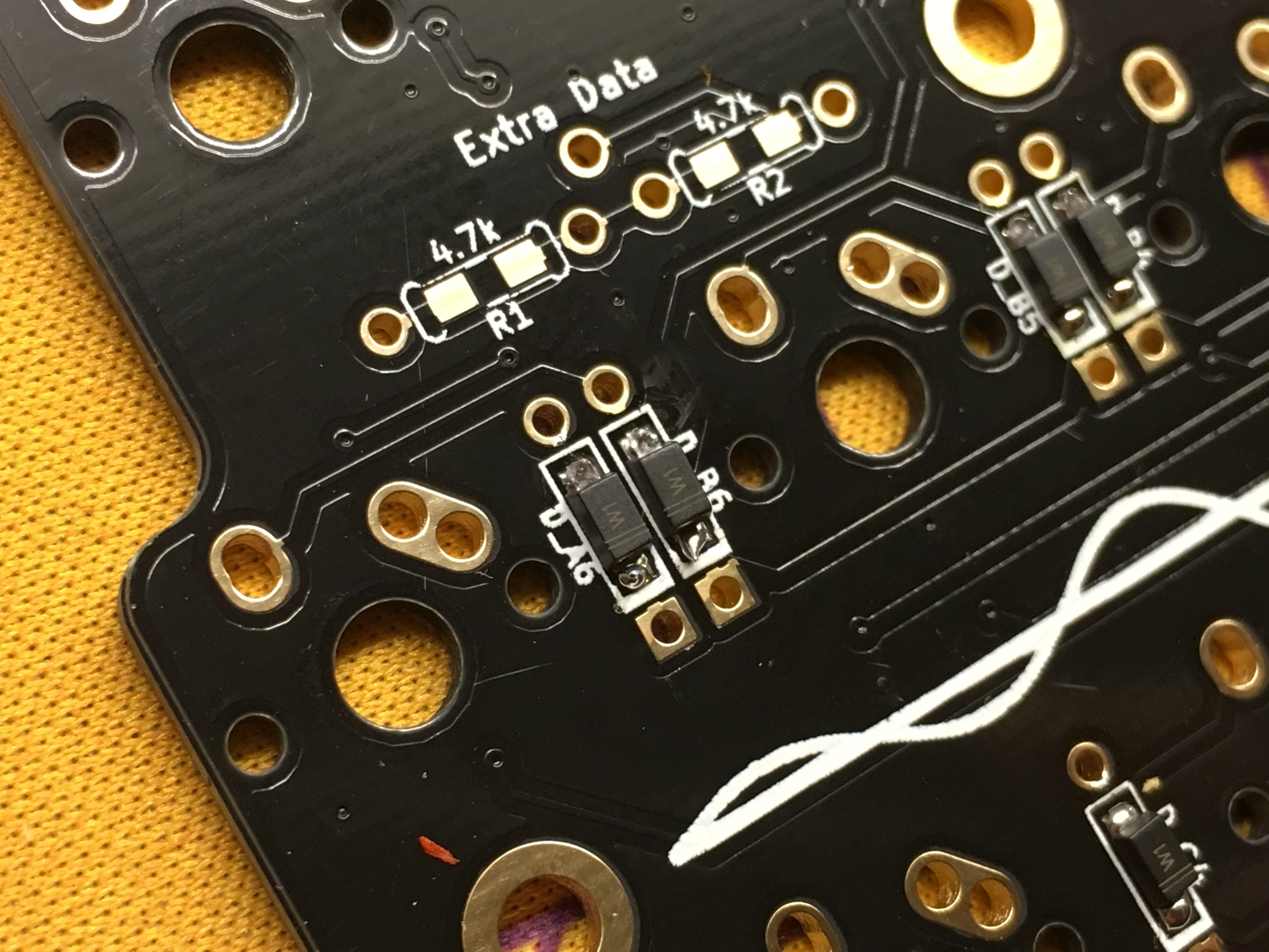
Another close up of the diodes so you can be the bands.
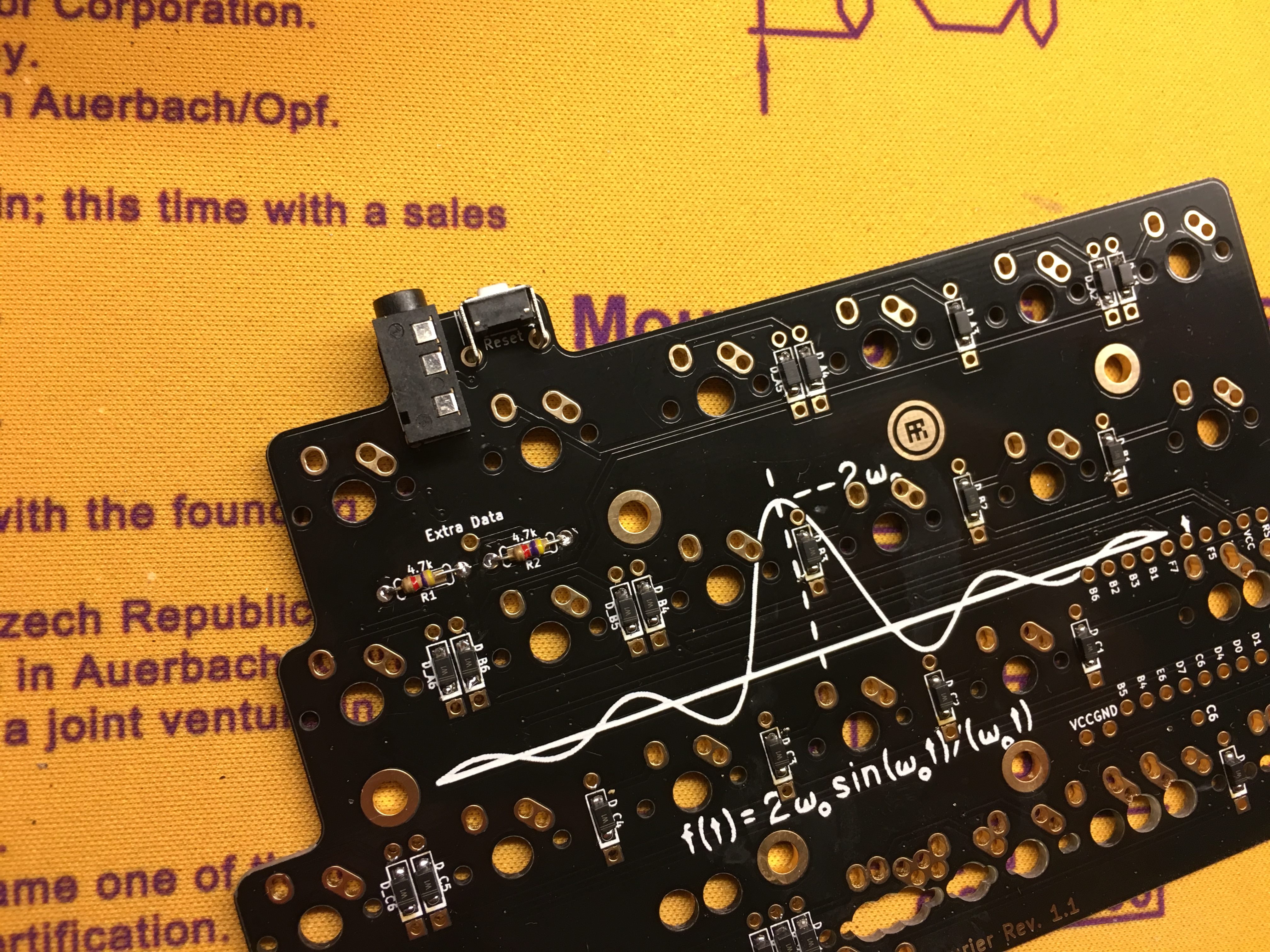
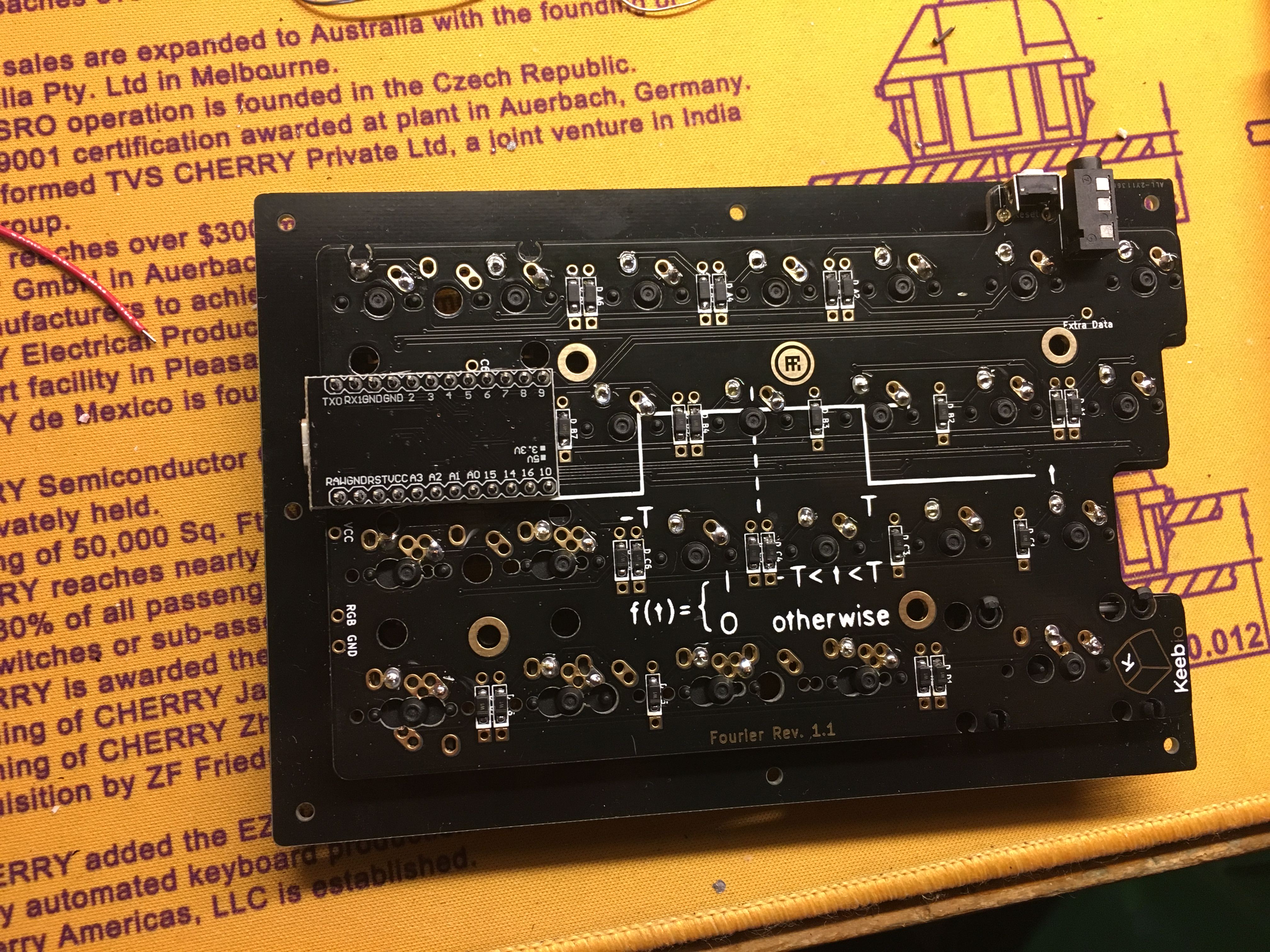
Install the I2C resistors (optional), the TRRS jack, and reset switch.
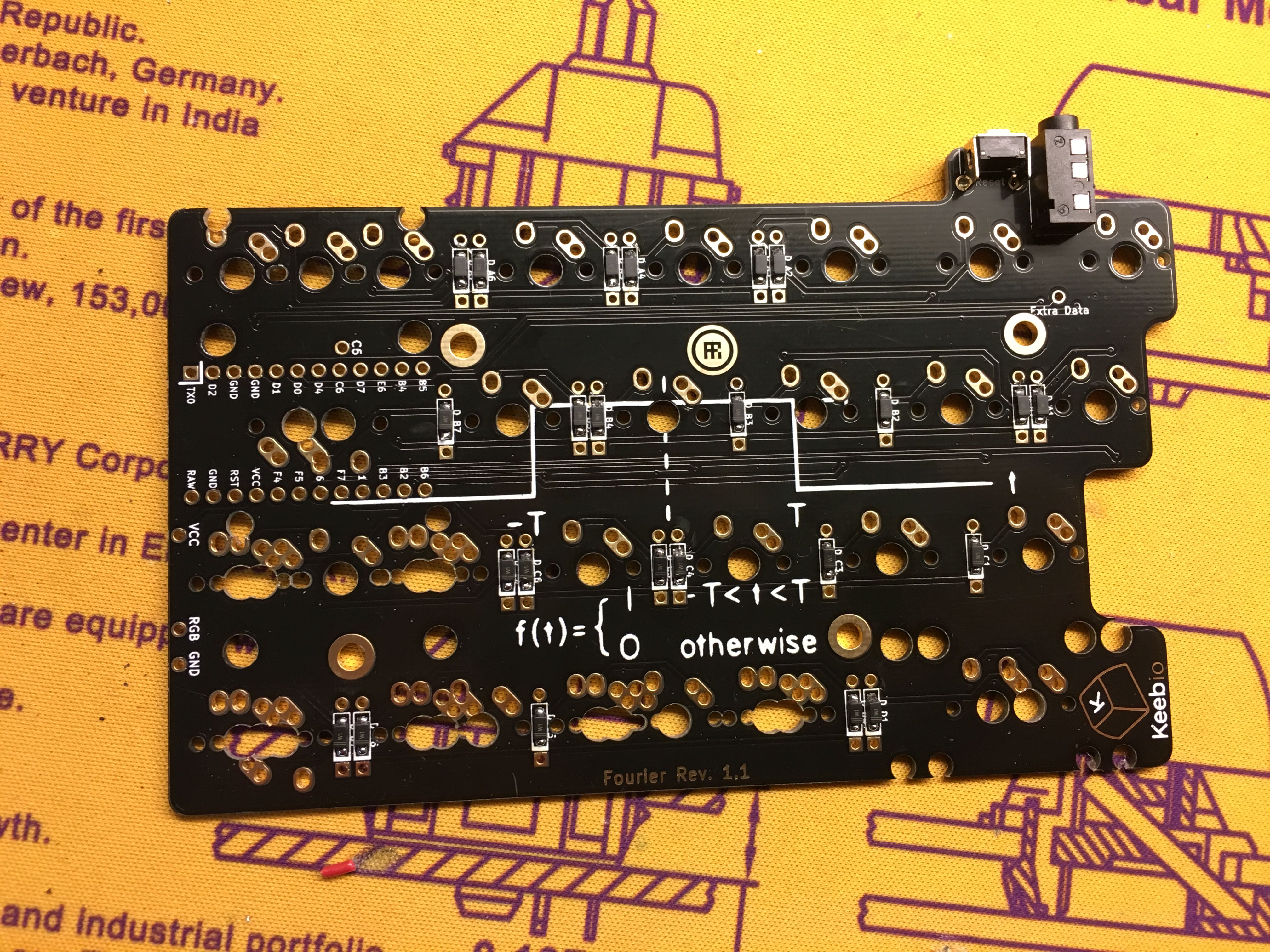
Repeat the same process with the diodes, TRRS jack, and reset switch with the right half. Note that there's no I2C resistor slots on this side, as they're only needed on one half.
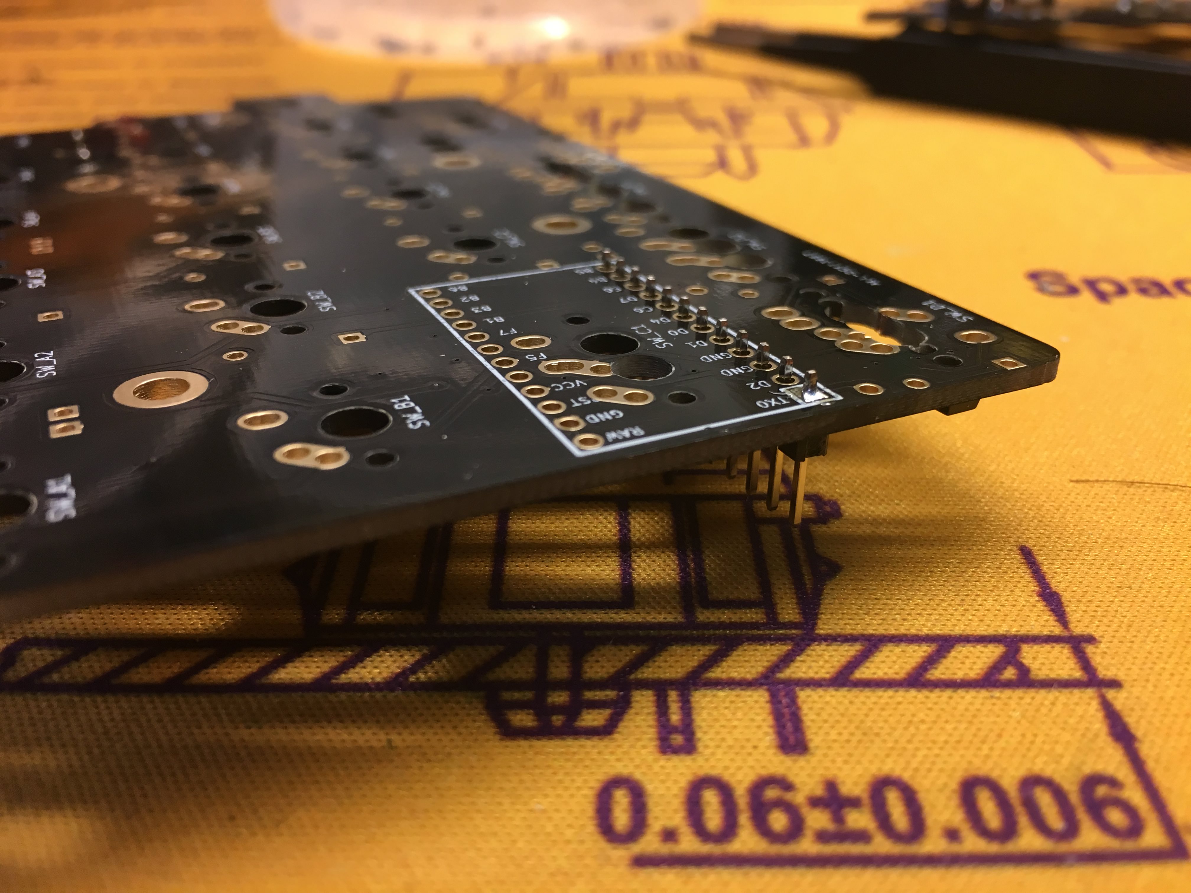
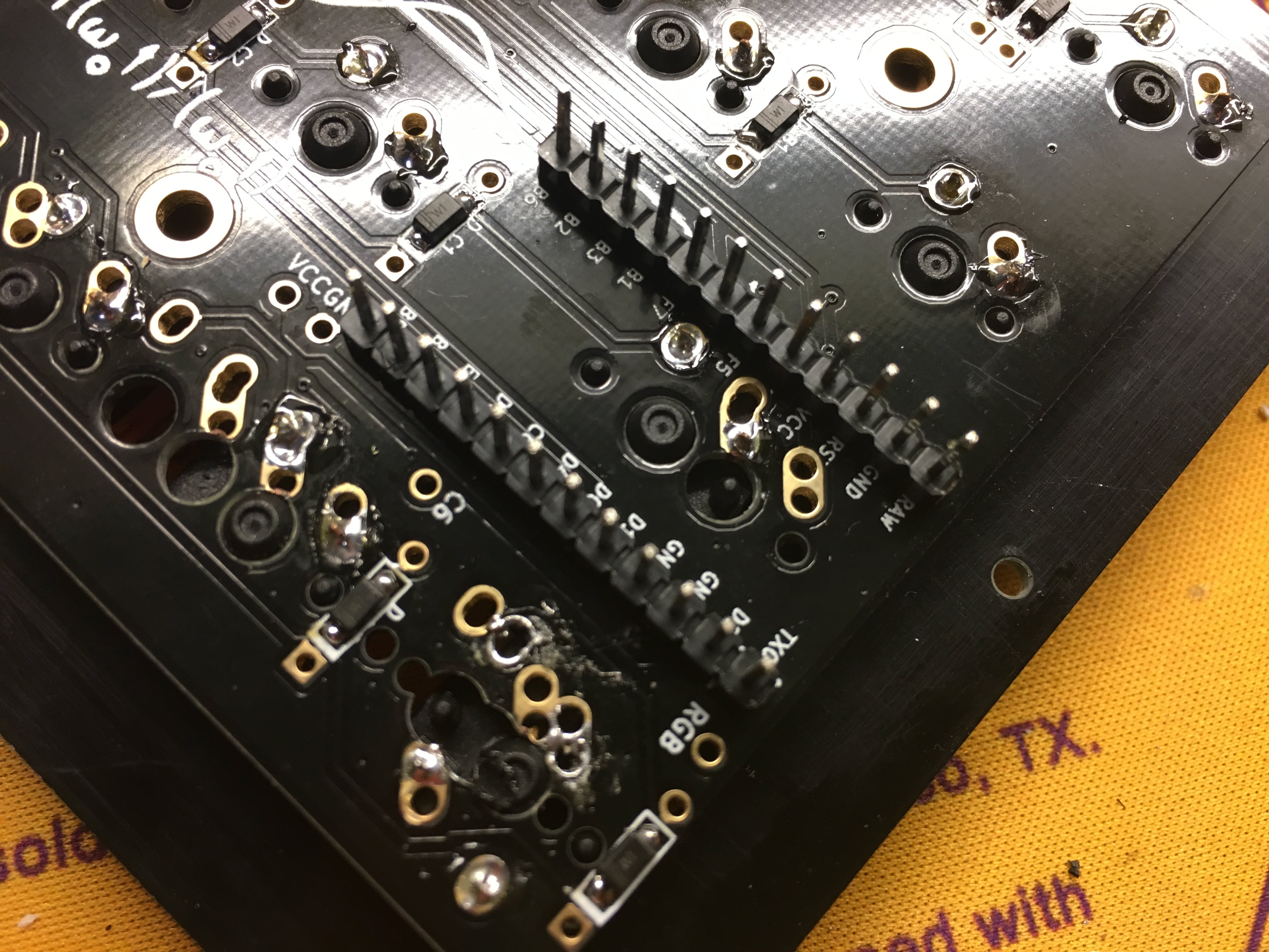
Solder on the header pins for the Pro Micro.
First technique: Put on first row of header pins and solder one pin. Then check to see if it's aligned properly before soldering the rest of the row.
Alignment after first row is good, solder the rest of the pins.
 1
1
Same thing with the other row of header pins, solder one pin first, check alignment, then solder the rest.
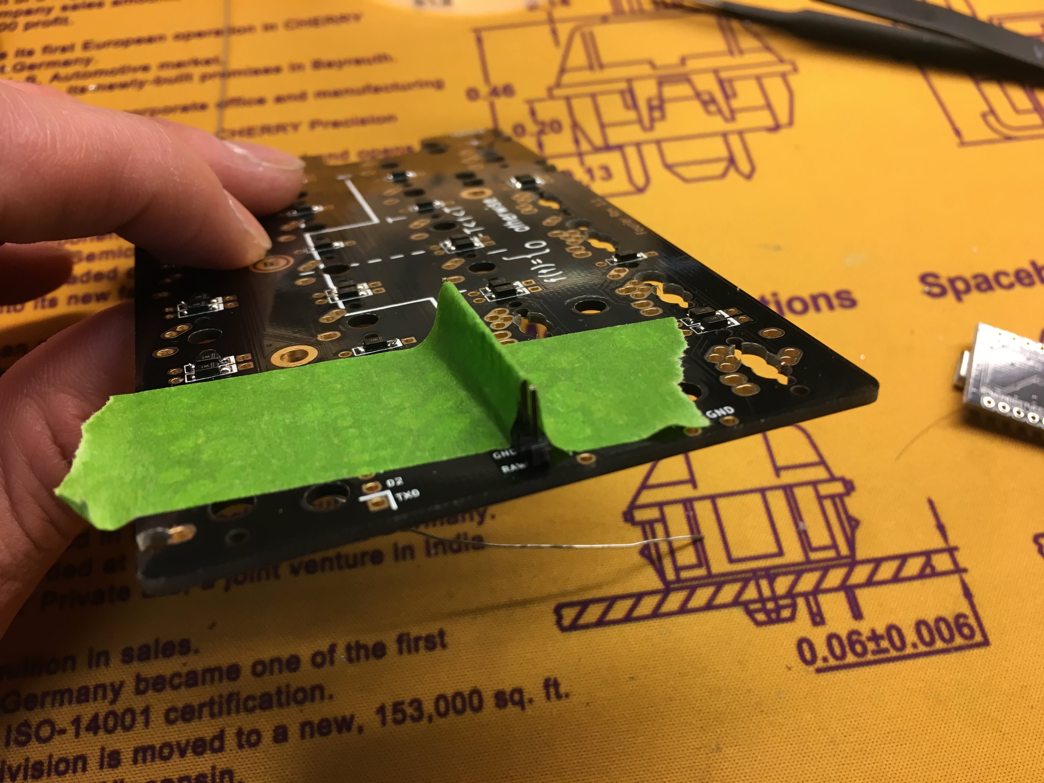
Second technique for soldering header pins on: Tape row of pins so they stay in place while you solder them in.
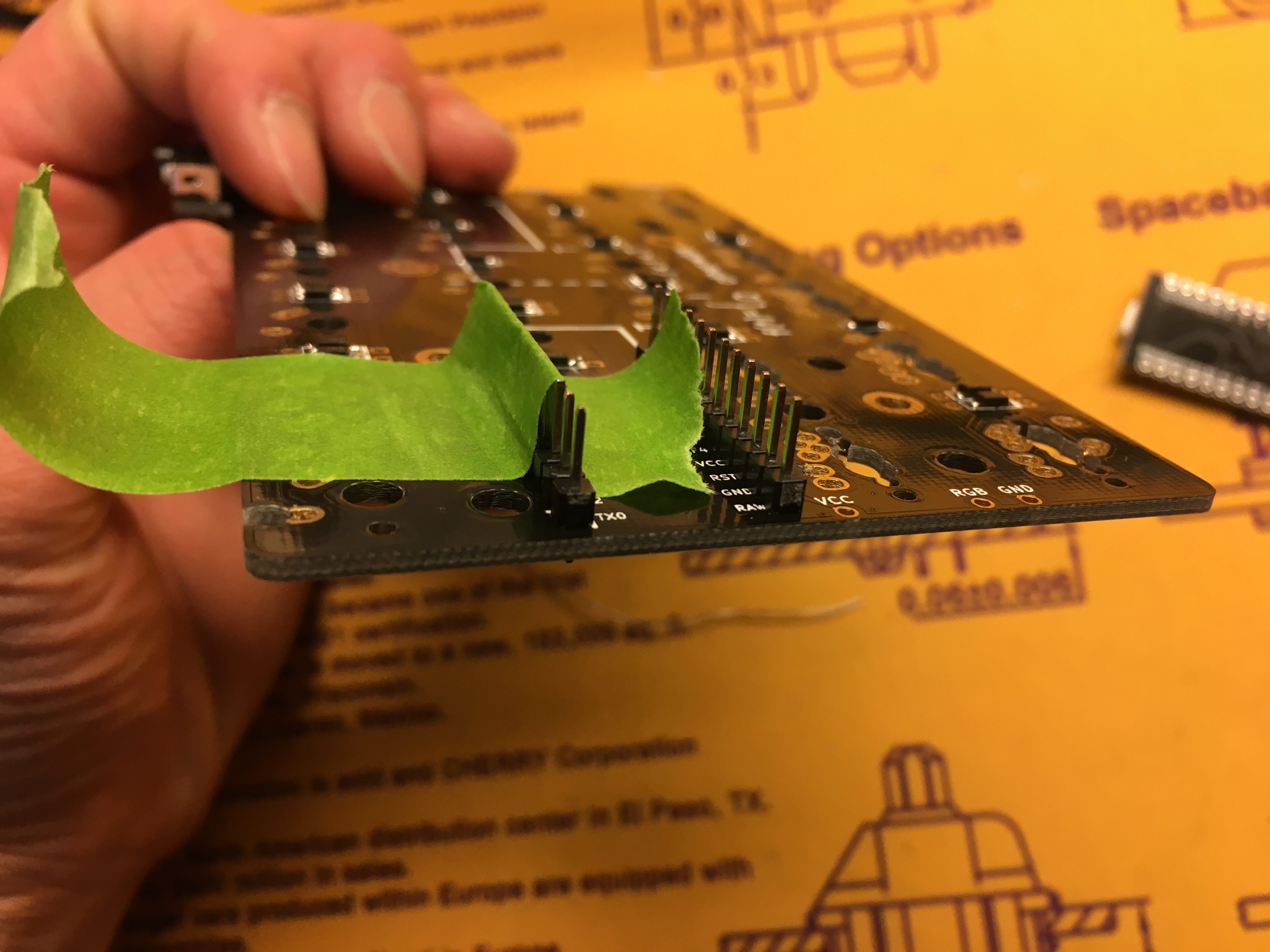
Repeat for the other row of pins.
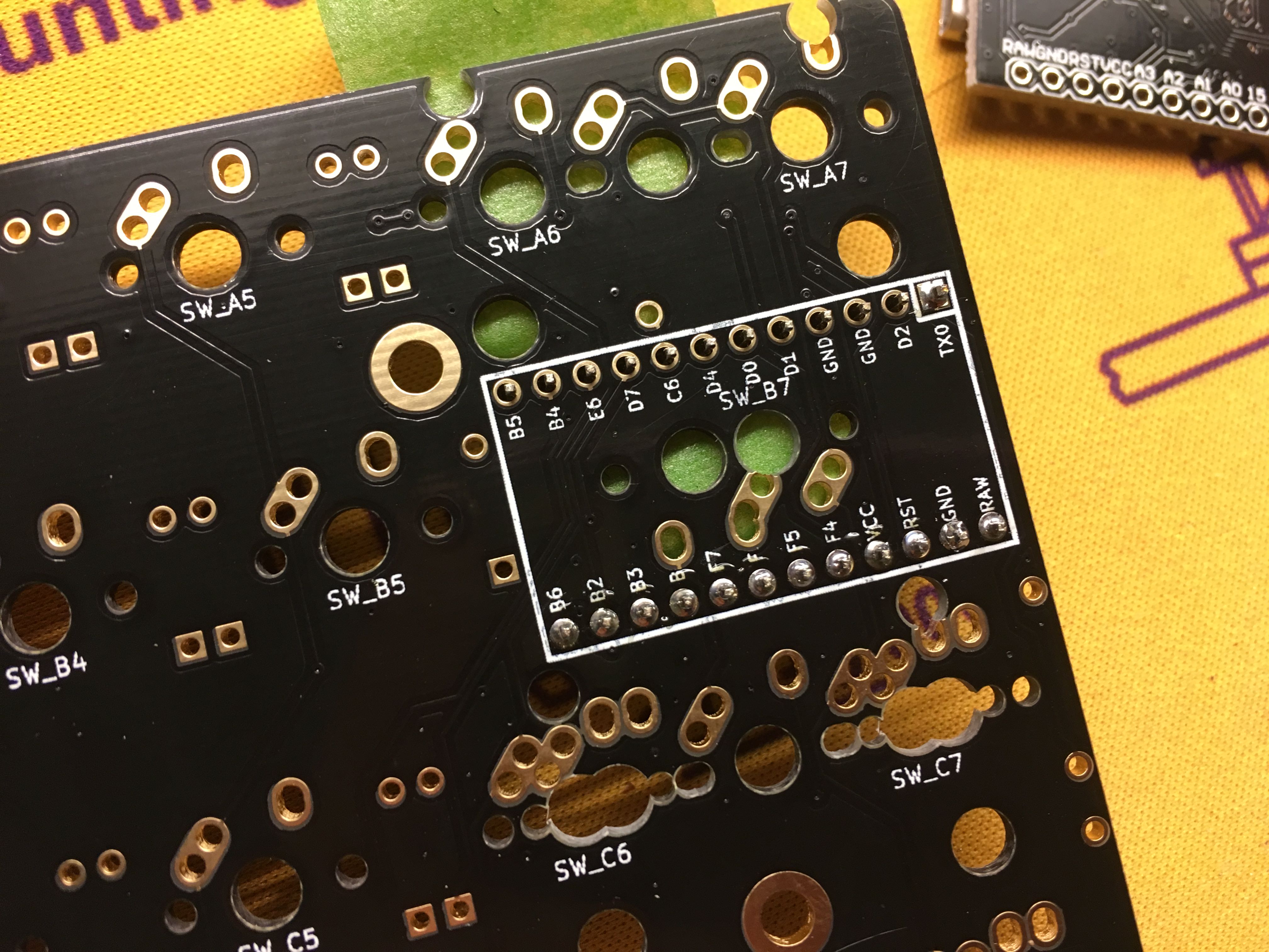
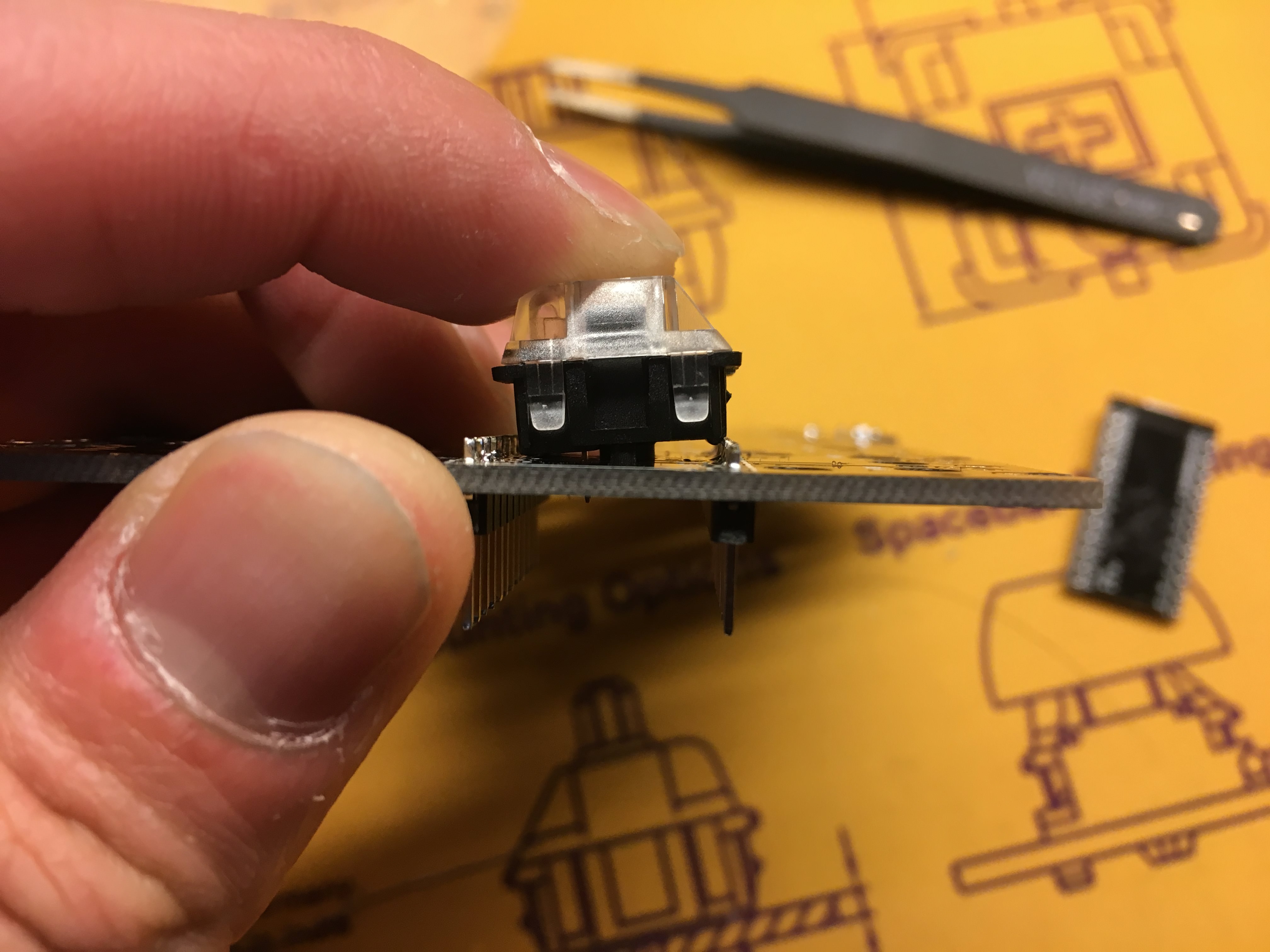
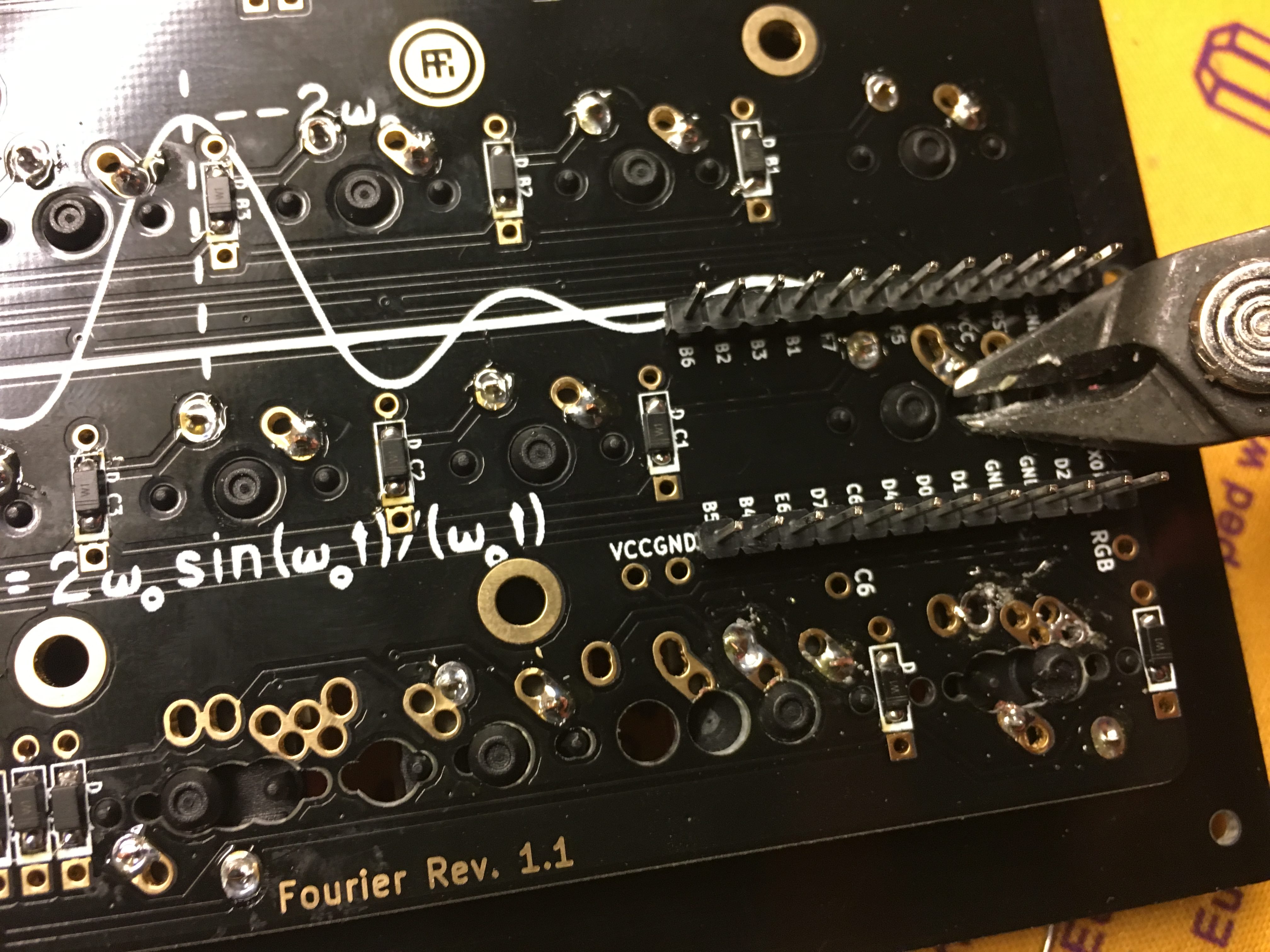
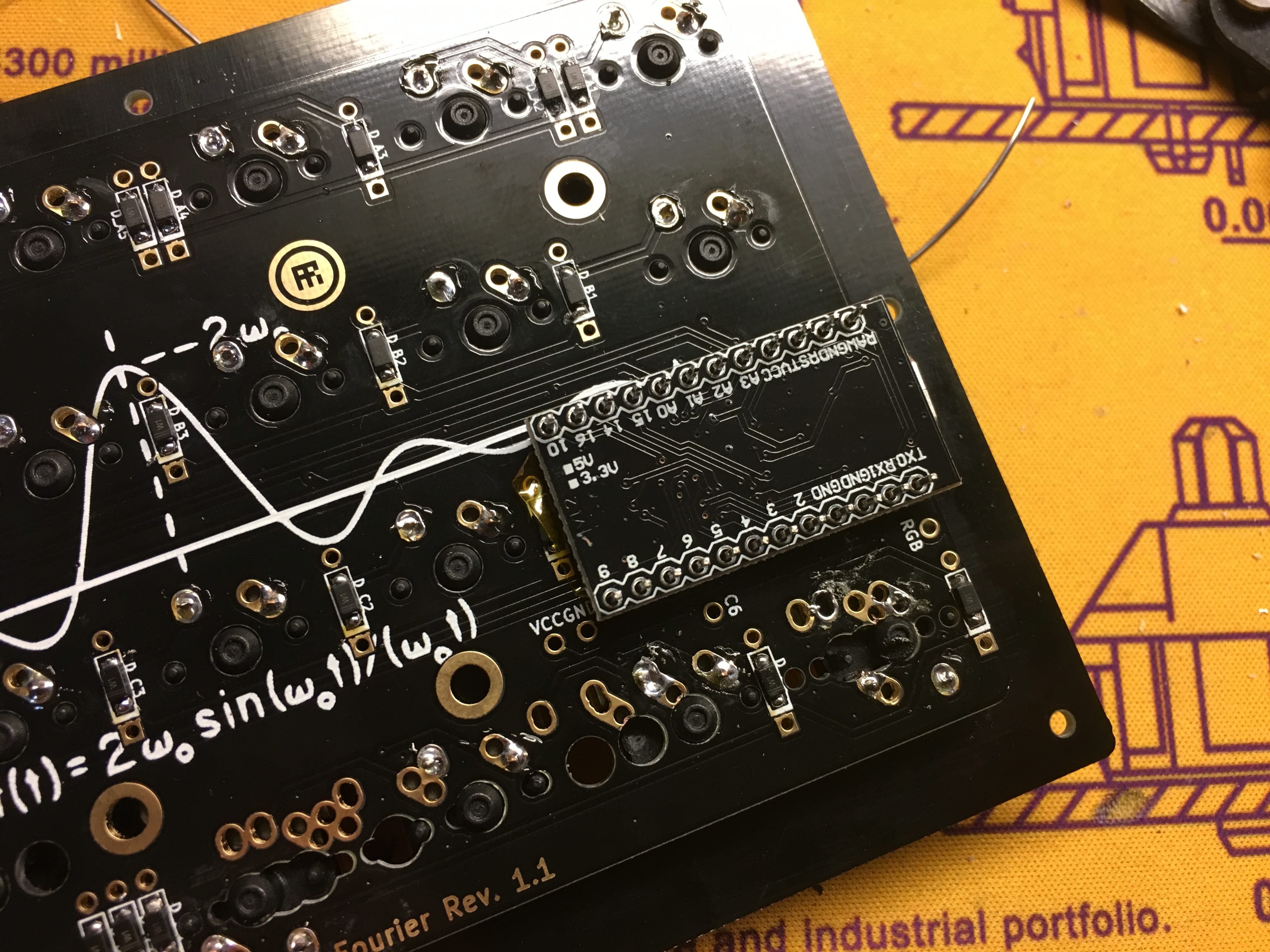
Due to the location of the stabilizers on the right half, the Pro Micro header pins needed to be situated a bit lower than usual. This interferes a bit with one of the switches, so the pins need to be trimmed down a bit on that side.
Another view which shows the pins that will need to be trimmed down.
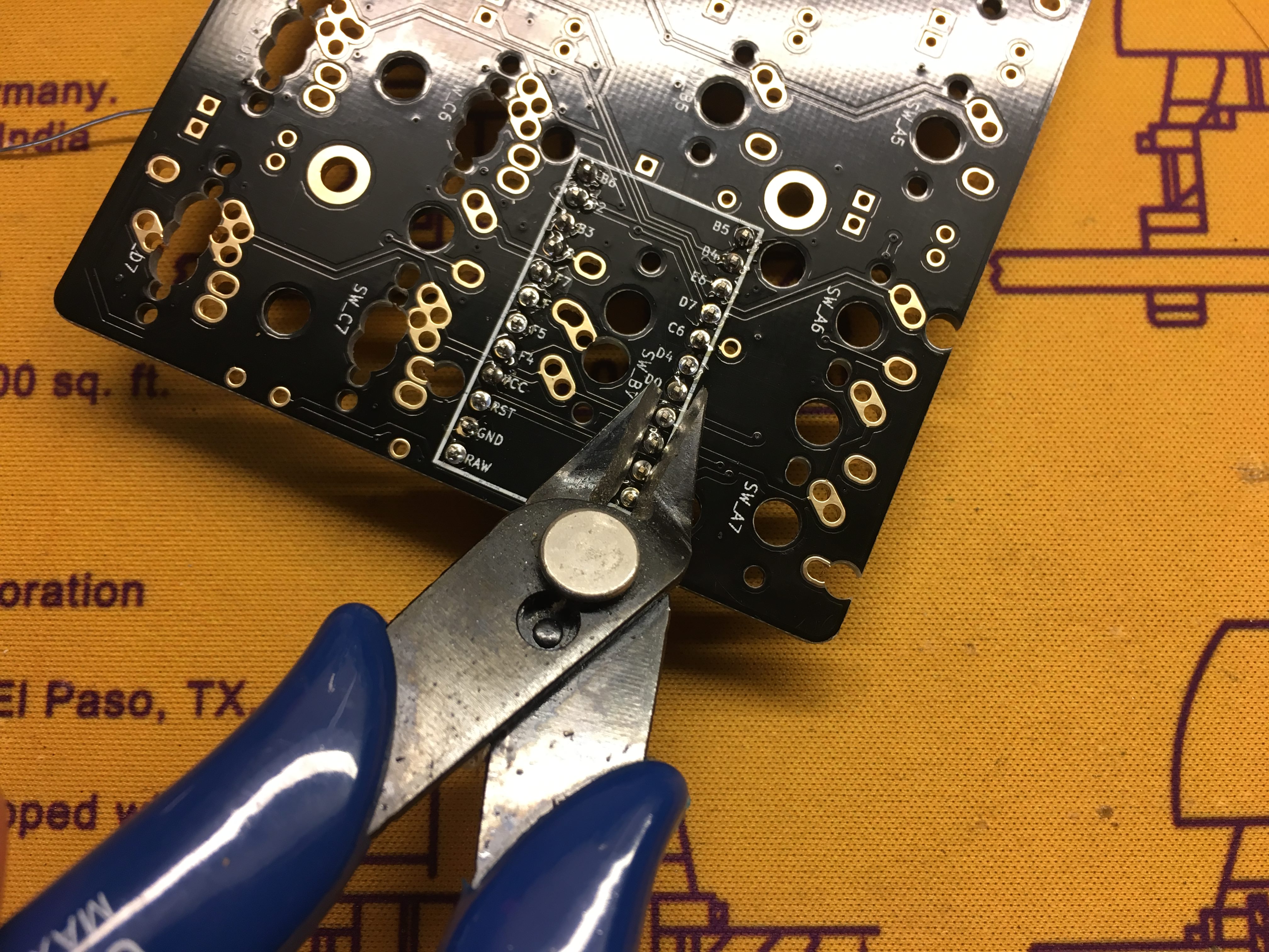
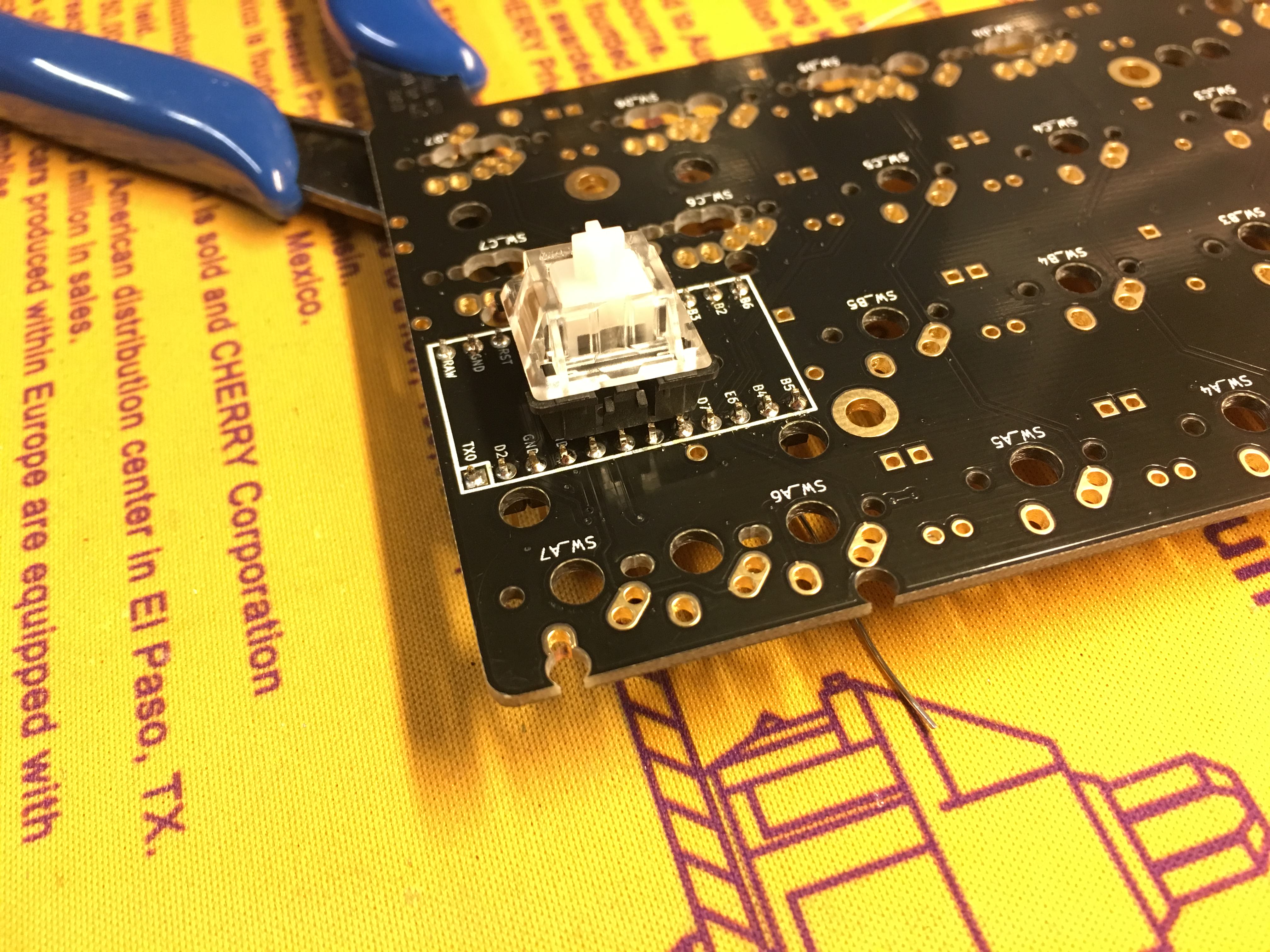
Take a flush cutter to trim the pins down.
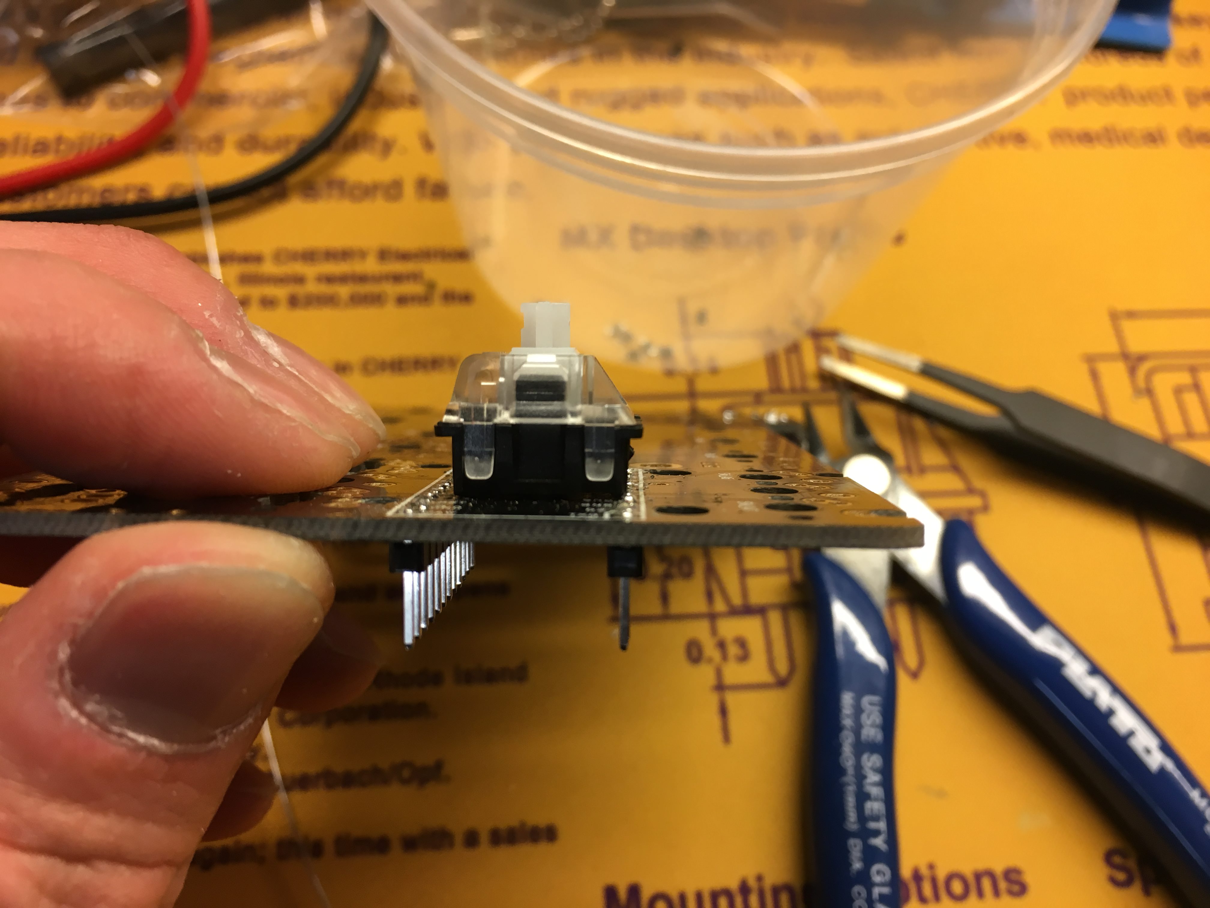
All good now, the switch sits flat on the PCB.
Add stabilizers to the keys you want to stabilize.
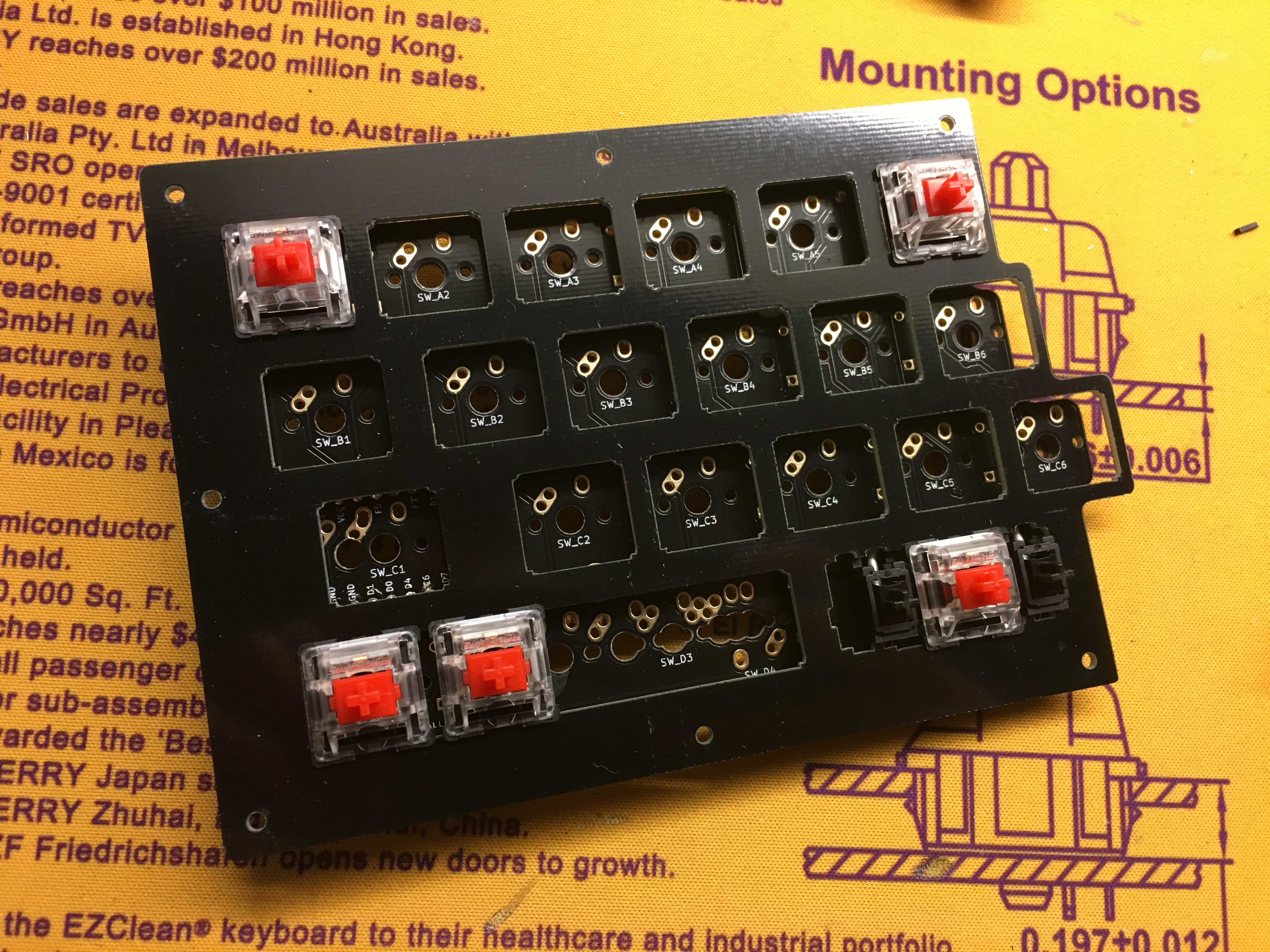
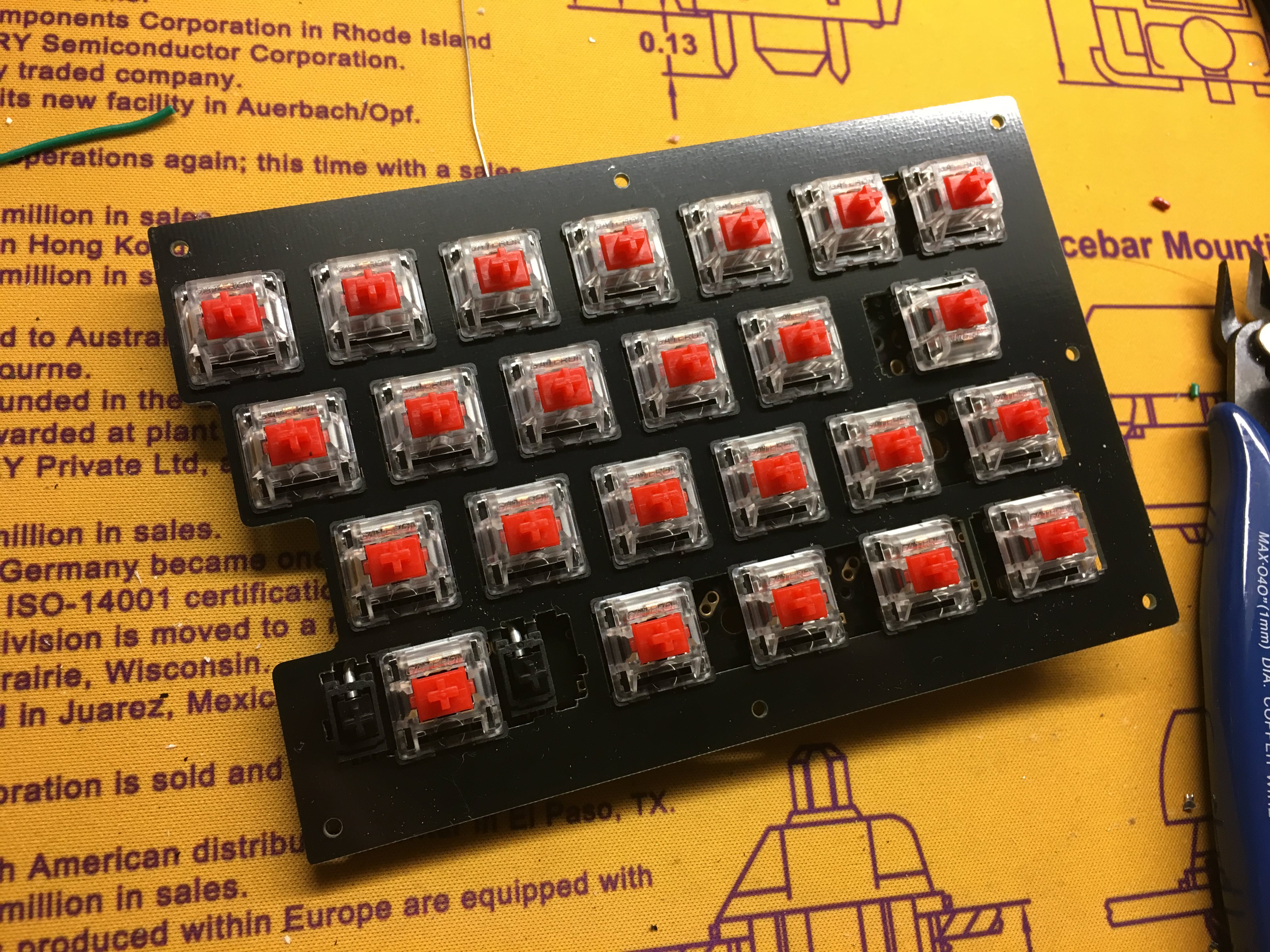
Time to add the switches. Put a few switches into the corners of the switch plate and then attach the switches to the PCB. Make sure the switches are pushed all the way down onto the PCB.
Due to the multiple layout options, it may be helpful to put keycaps on the switches to make sure everything is in the correct slots.
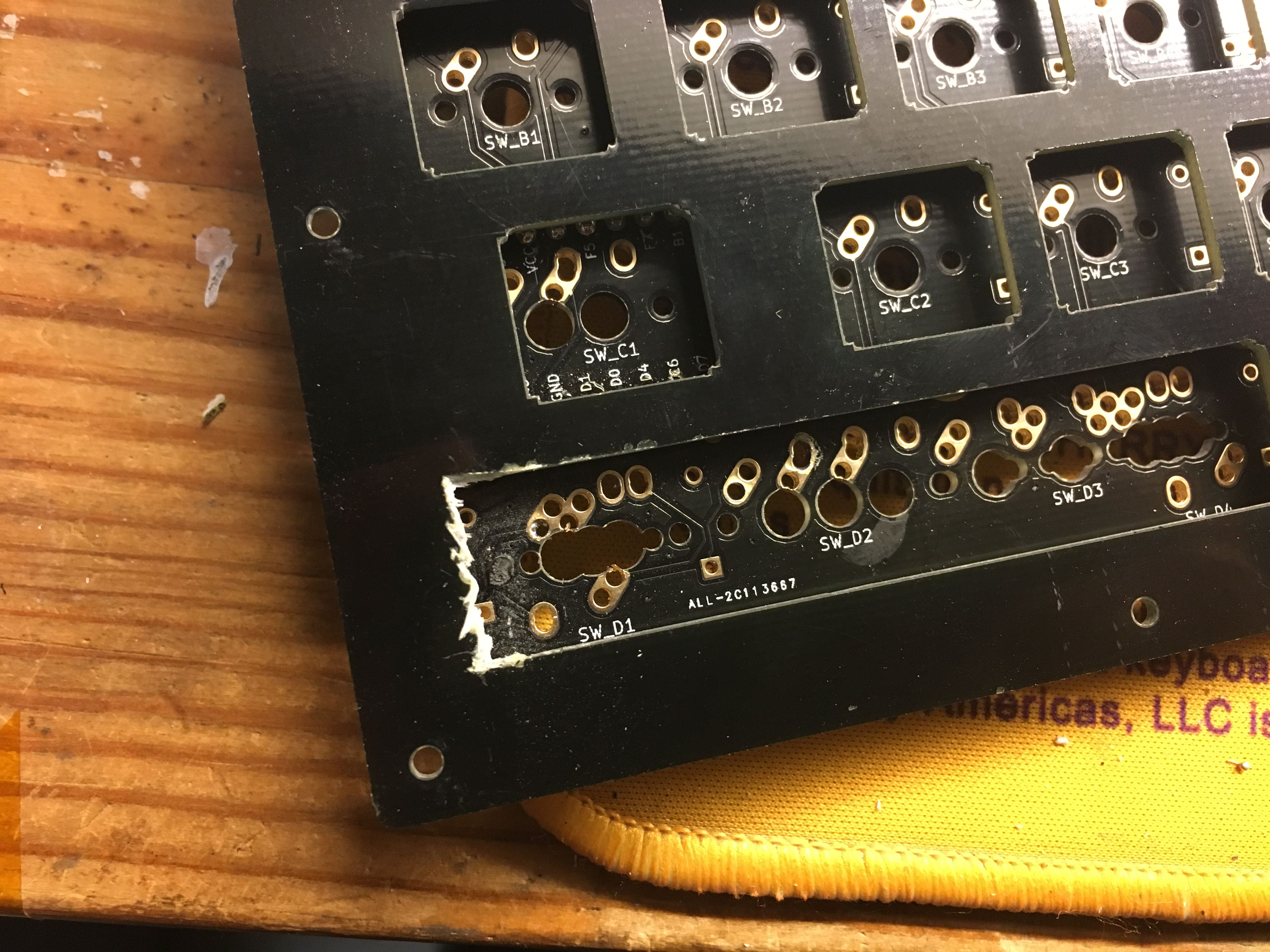
If you paid attention closely to the previous picture, the lower left switch was too close to the one to the right of it to properly do a 4x1u configuration on the bottom row. Turns out I forgot to expand the cutout width when I added support for that configuration. This has already been fixed in the next version of the plates.
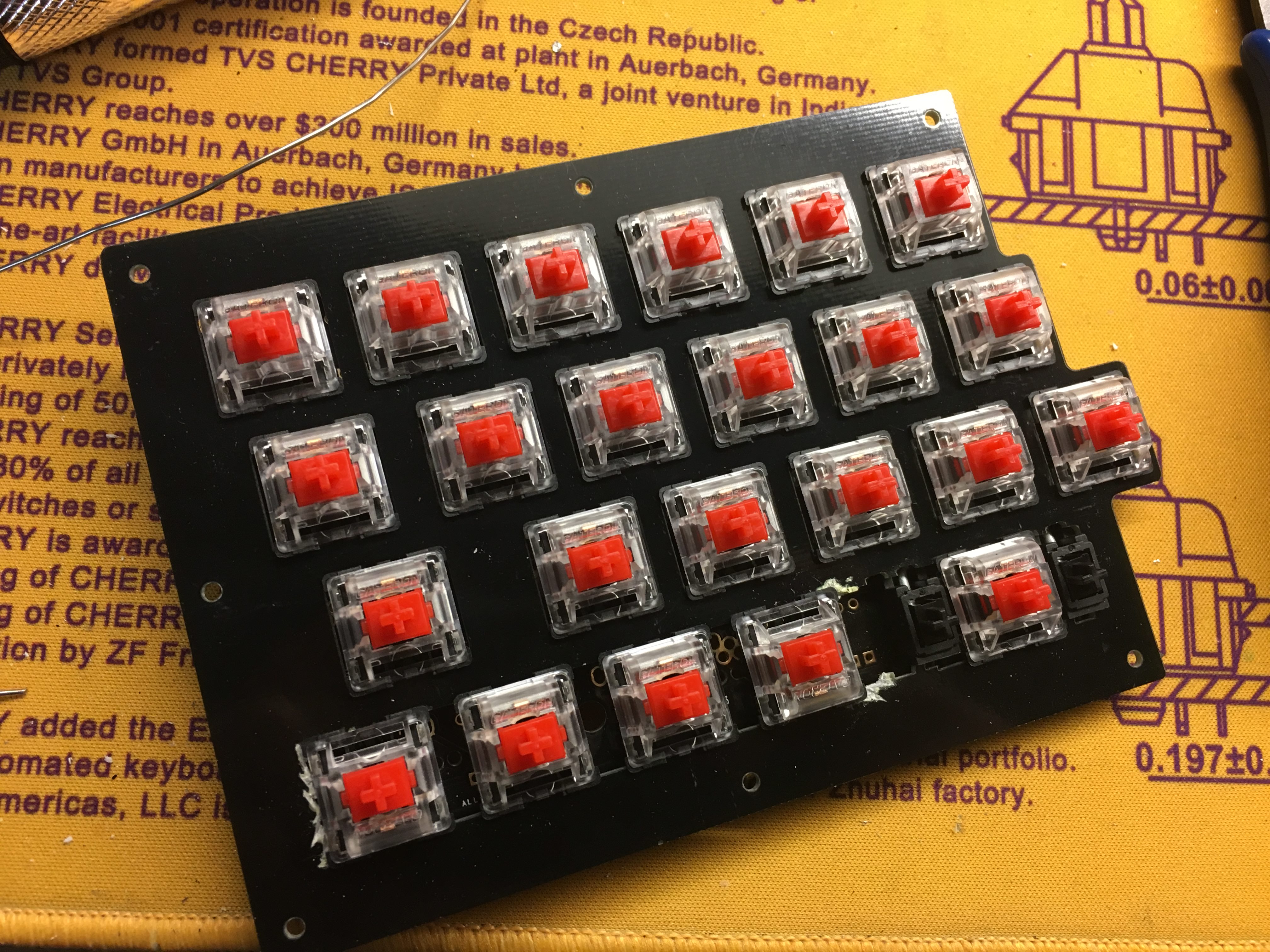
All the switches installed and soldered in.
Time to install the Pro Micro now that the switches have been soldered in.
To make sure that the switch pins don't touch the Pro Micro, clip them flush with the PCB.
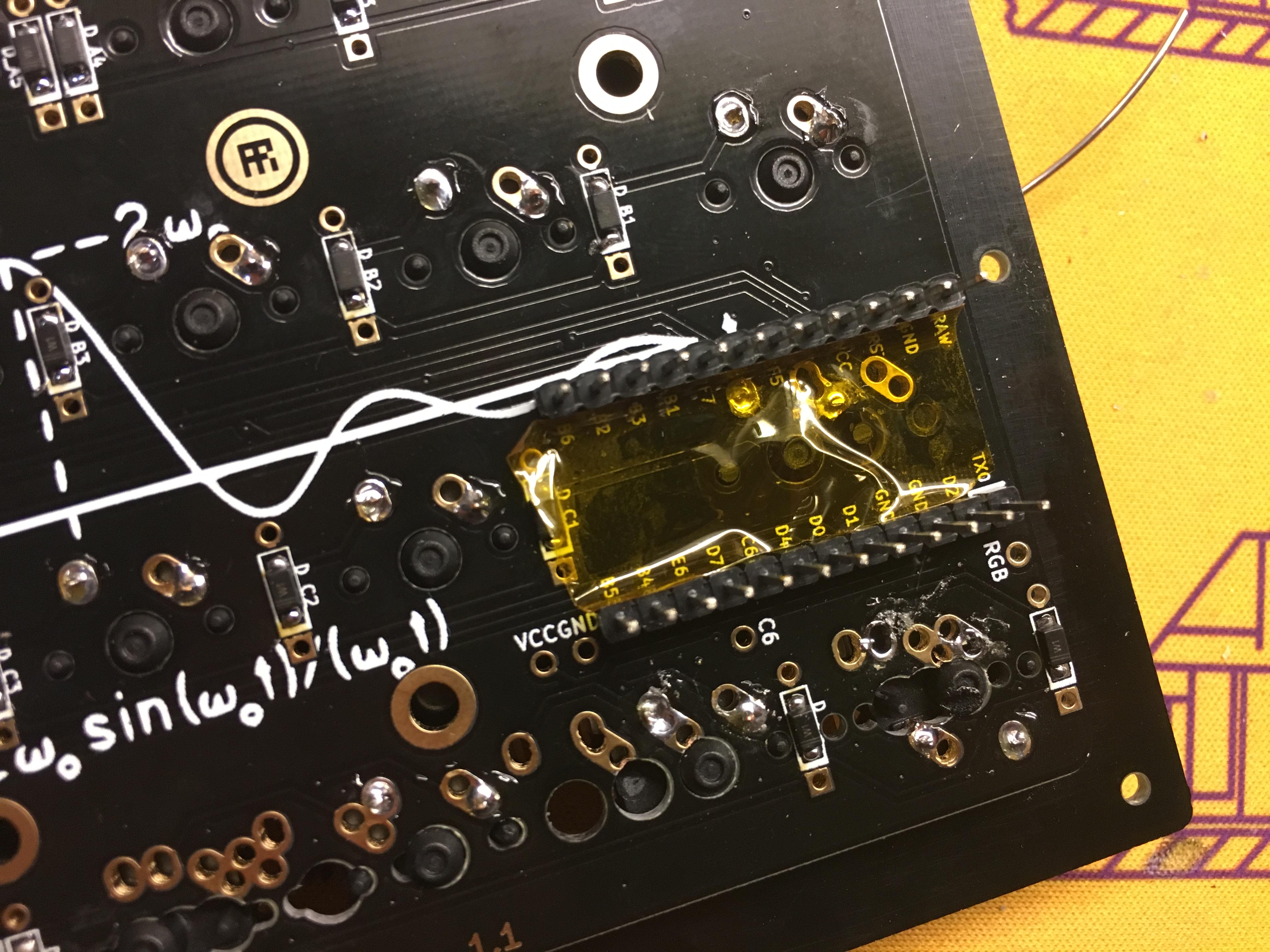
Afterwards, add Kapton or electrical tape on top of it.
Now go flash your Pro Micro before installing it on the board. Better to find out if it's defective or not before it's soldered on.
Place the Pro Micro on the header pins. On both PCBs, the component side of the Pro Micro will be hidden from you.
Don't install it backwards, it doesn't flip the layout or anything like that, it doesn't work in that way.
Repeat the process of stabilizer, switch, and Pro Micro installation on the right PCB.
Once again, the component side of the Pro Micro will be hidden from you.
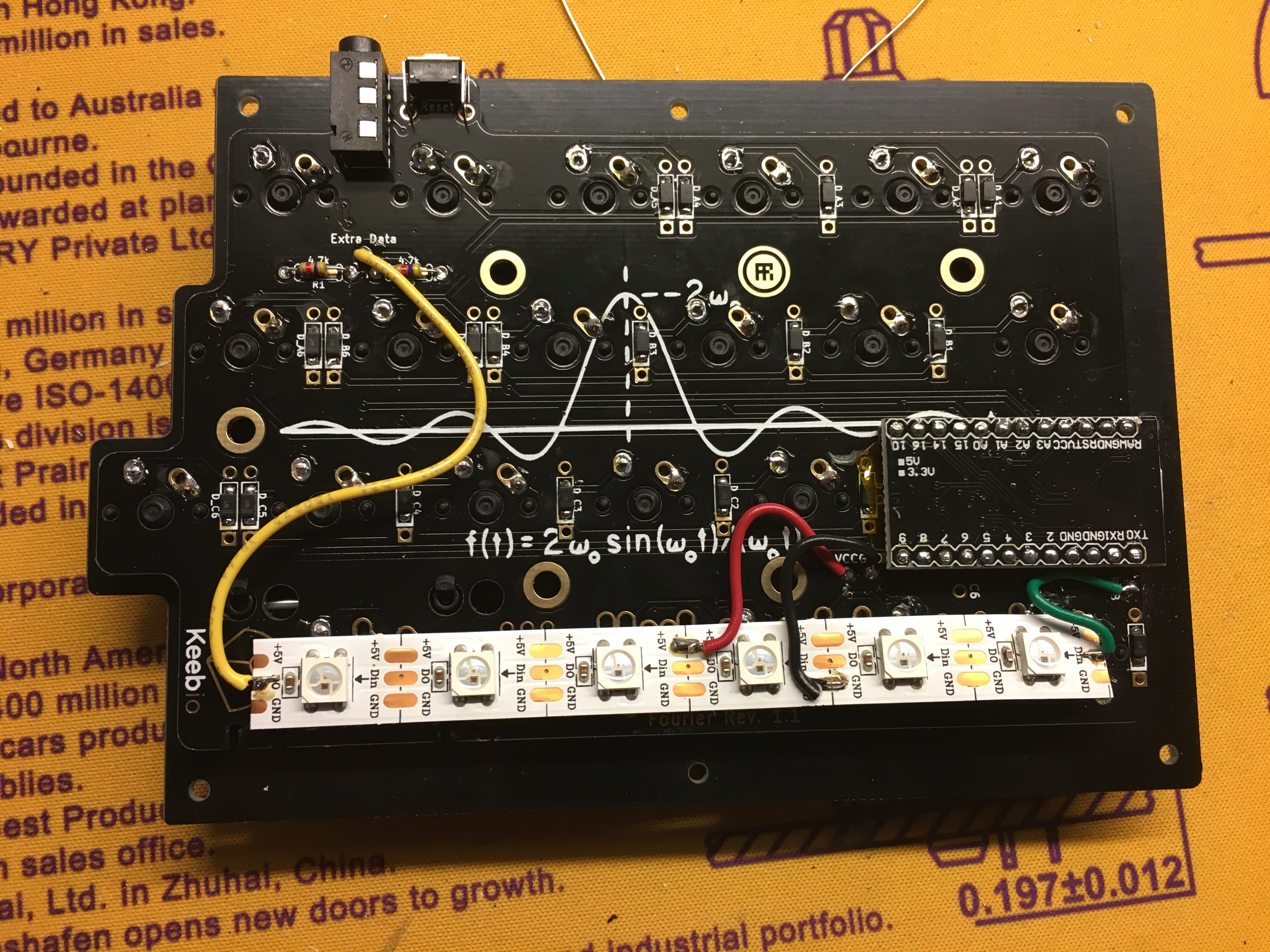
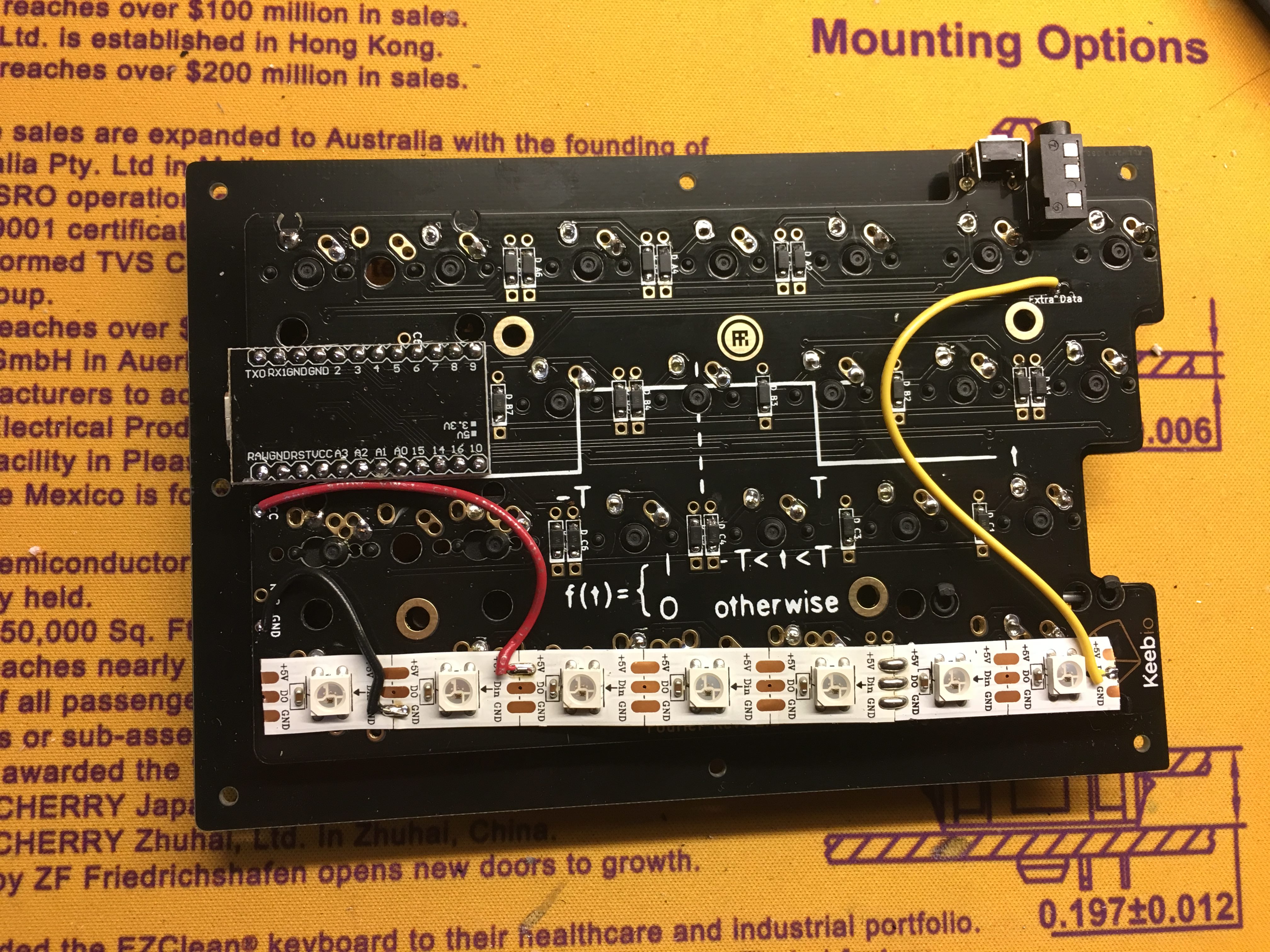
Optional, add RGB strip. For the left half here's what to connect:
- RGB breakout goes to Din on strip
- VCC breakout goes to +5V on strip
- GND breakout goes to GND on strip
- Extra Data goes to Do/Dout on strip
Pro Micro added to the right PCB. Here's what to connect for the right half:
- VCC breakout goes to +5V on strip
- GND breakout goes to GND on strip
- Extra Data goes to Din on strip
- RGB breakout remains empty for now
Assemble the case by adding screws, standoffs, and bottom plates.