Iris Rev. 2
Build guide compatibility
While this build guide shows parts for the Iris, the build is very similar to that of the Levinson, as well as the Nyquist Rev. 2, since they all have in-switch LED support.
Do not use this guide due to the difference in the order of build steps. For that PCB, use the Iris Kailh Low-Profile Build Guide instead.
Previous Guides/Info
- LED fix for right PCB of Rev. 2.1b or 2.4, in case you soldered the MOSFET to the side with the bad trace: Rev. 2.1b/2.4 LED Fix
Videos of Builds
Here's a list of Iris build videos various people have created:
- TaeKeyboards - Iris Split Ergonomic Mechanical Keyboard Build
- Juju - Iris Split Mechanical Keyboard Build!
- Missouri Valley Tech - Iris Split Ergonomic Keyboard Build Log
- iammeuru - Build: Iris
Other Blogs/Guides
Here's alist of Iris build guides, blogs, and other things people have created:
Parts List
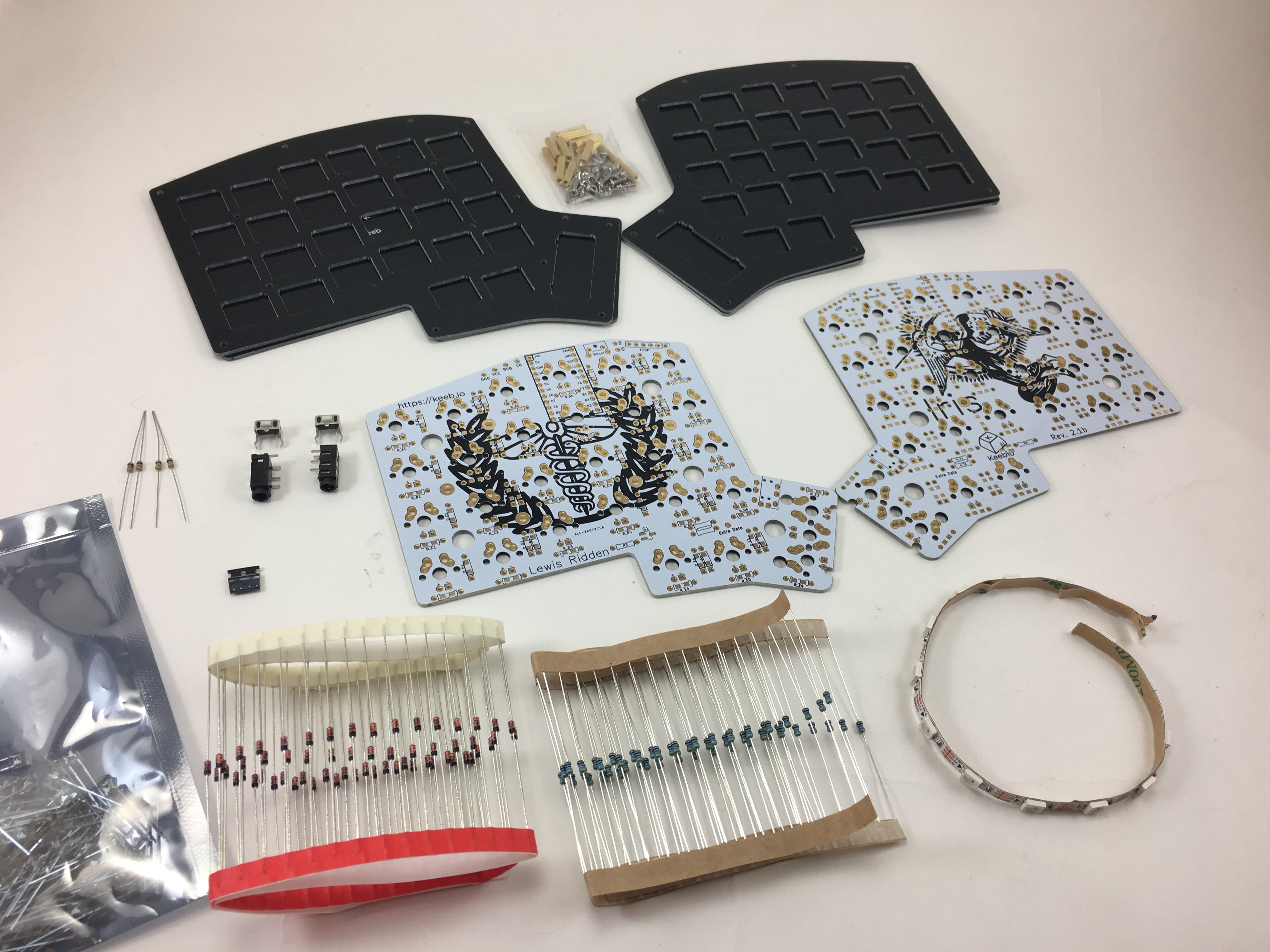
Here's a list of parts needed for the build:
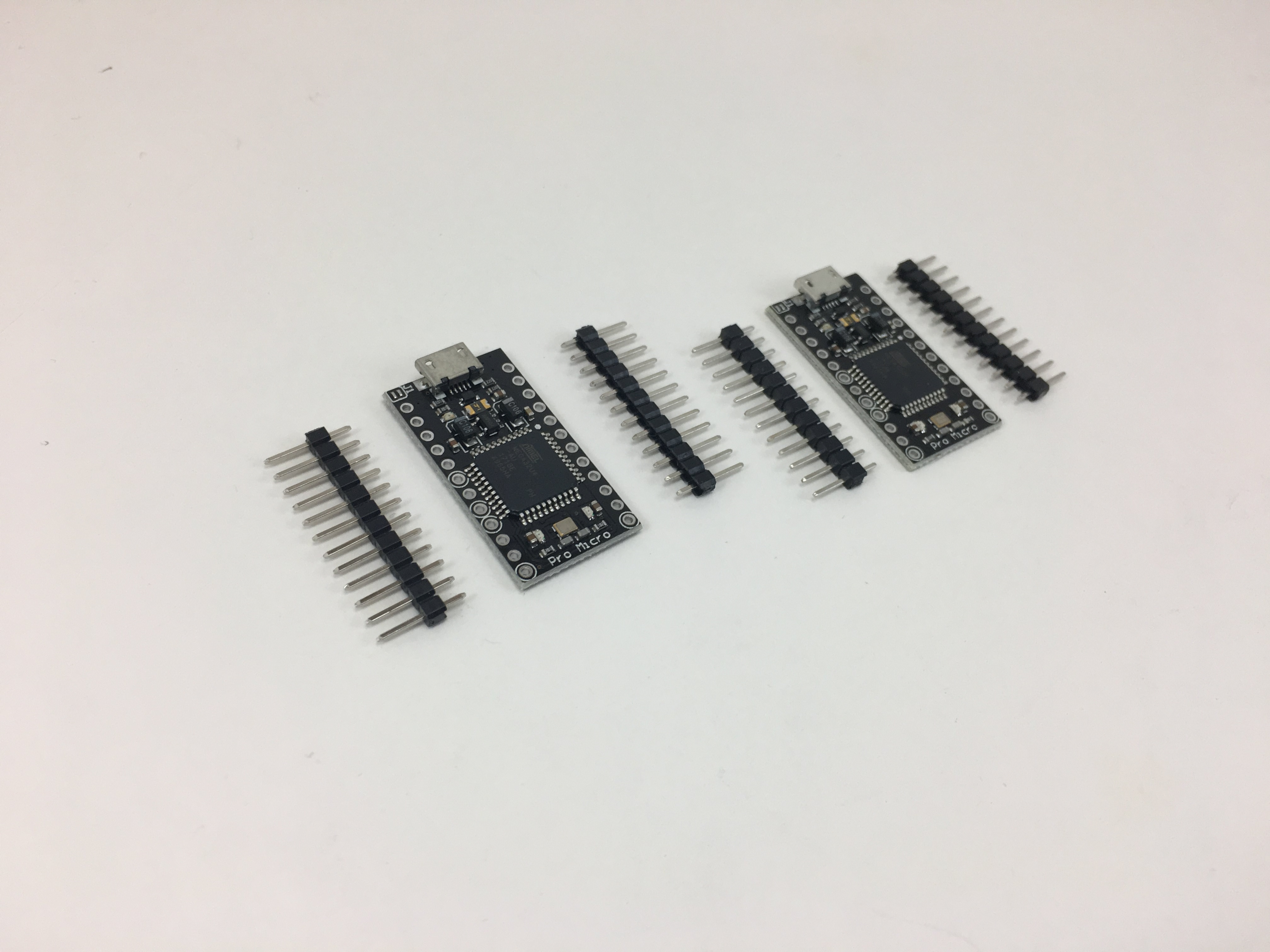
All of the parts needed are shown here, except for Pro Micros, TRRS cable, and switches
- 2 sets Top/Bottom plates with M2 screws and standoffs
- 2 Iris PCBs
- 2 TRRS jacks
- 1 TRRS cable
- 2 reset switches
- 4 4.7kΩ resistors
- 2 used for I2C
- 1 used for LED support on left half
- 1 used for LED support on right half)
- 54-56 1N4148 diodes - through-hole (shown) and SMD diodes supported
- 54-56 470Ω resistors (optional, for LED backlight)
- 54-56 LEDs (optional, for LED backlight)
- 2 N-channel MOSFETs (optional, for LED control)
- WS2812B RGB LED Strip (optional, for underglow)
- 2 Arduino Pro Micros
- 54-56 switches (MX-compatible and Alps switches are supported)
- Optional parts (not shown)
- 2u PCB mount MX stabilizers if using 2u keys
Build Steps
Here's a summary of the build steps:
- Prepare components
- Solder components
- Solder diodes
- Solder push button and TRRS jacks
- Solder I2C resistors (optional)
- Solder LED components (MOSFET and resistors) (optional)
- Solder Pro Micro header pins
- Add 2u stabilizers (optional)
- Solder switches
- Solder LEDs (optional)
- Flash Pro Micros
- Solder Pro Micros
- Solder RGB strip (optional)
Prepare components
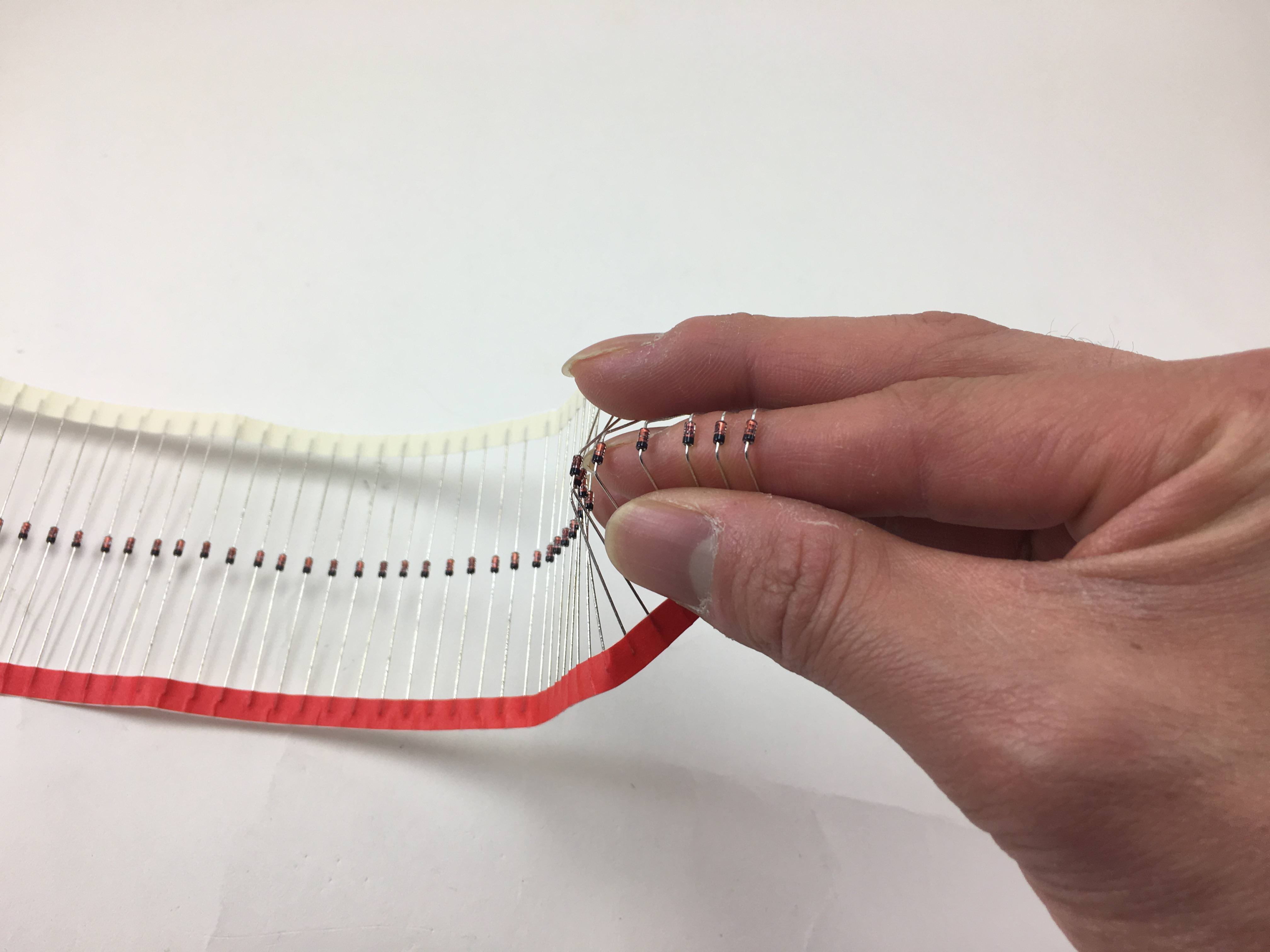
Bending the diodes. Here, I'm just bending it around my finger
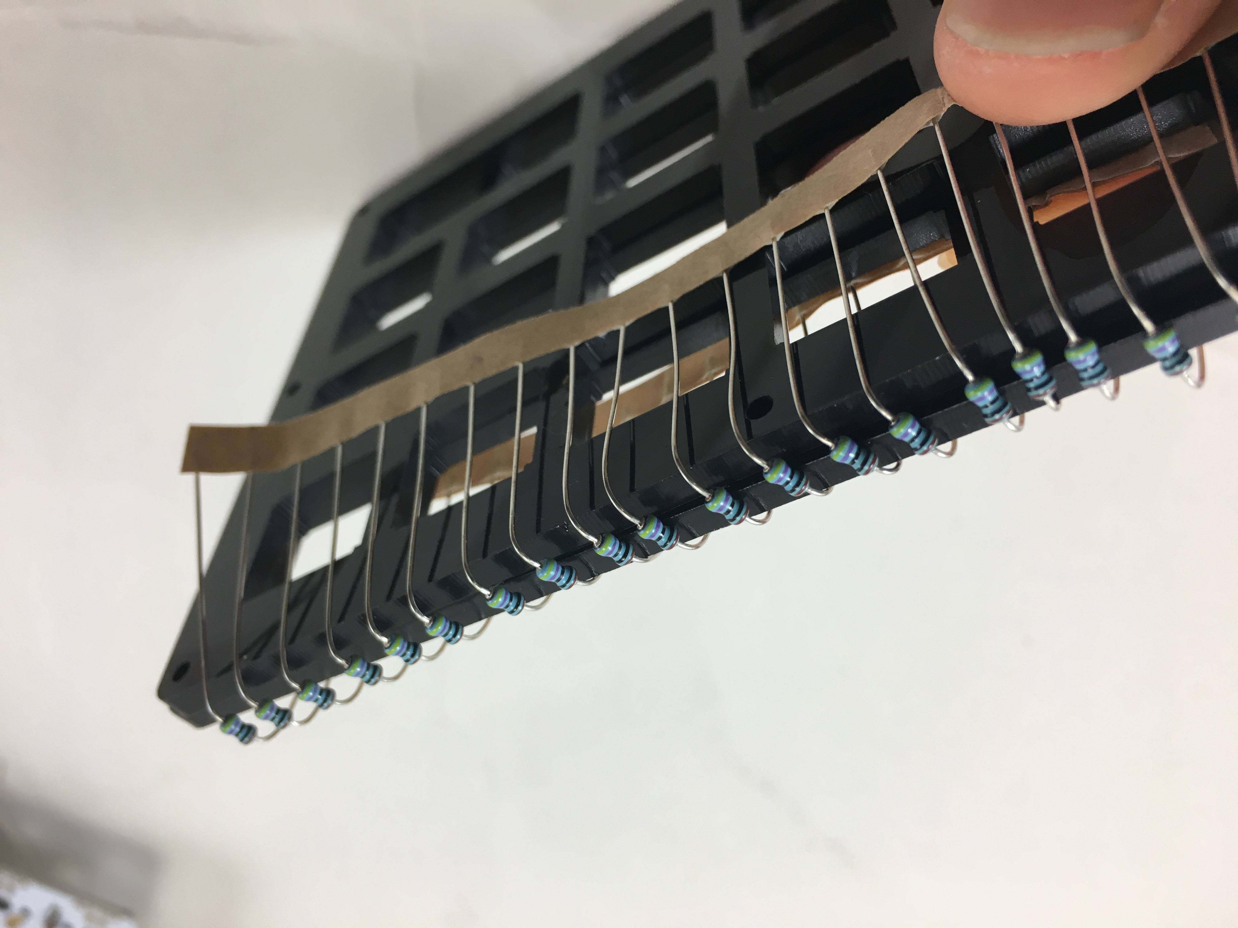
Another way to do it, resistors shown here
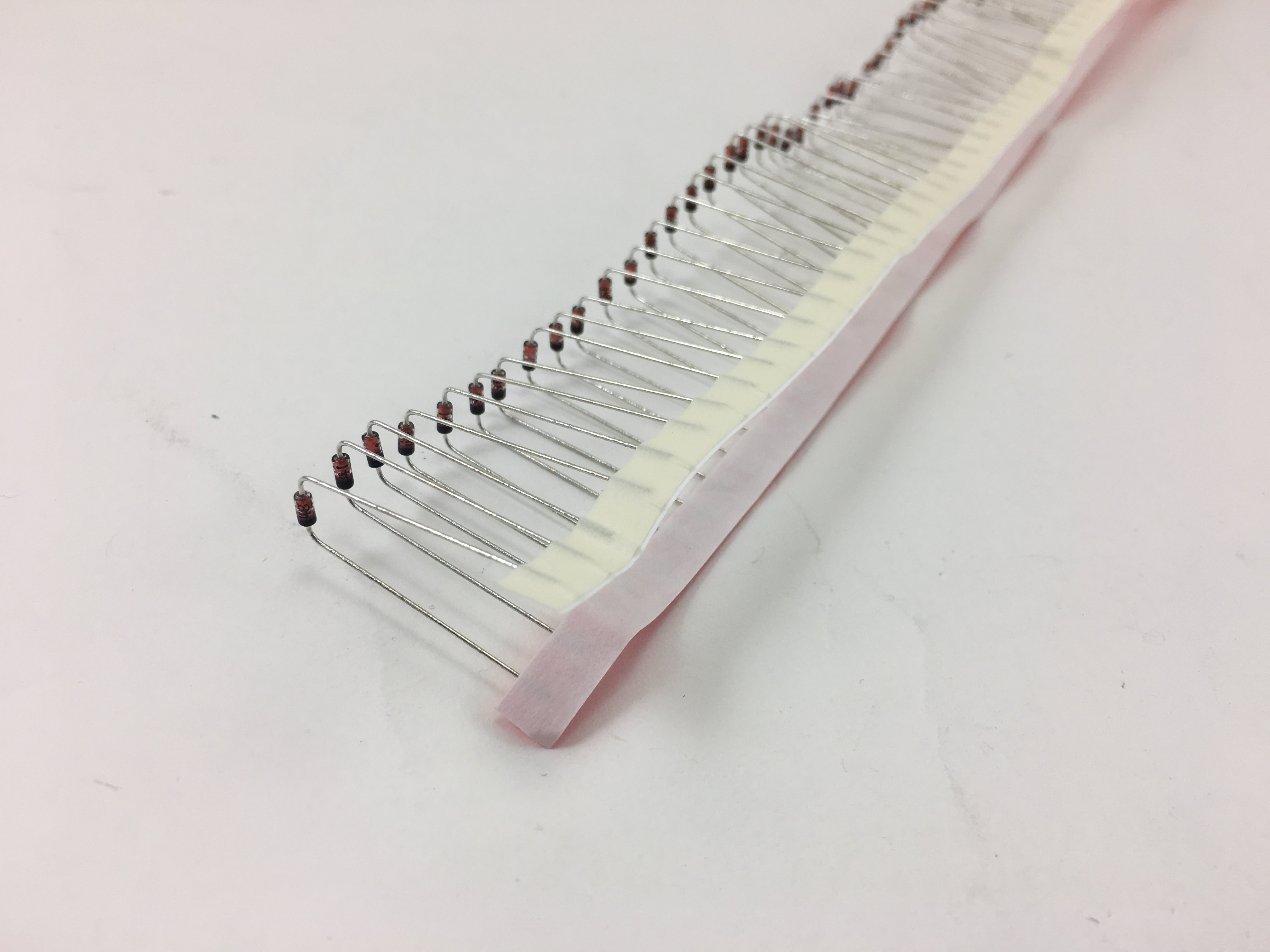
Strip of diodes bent
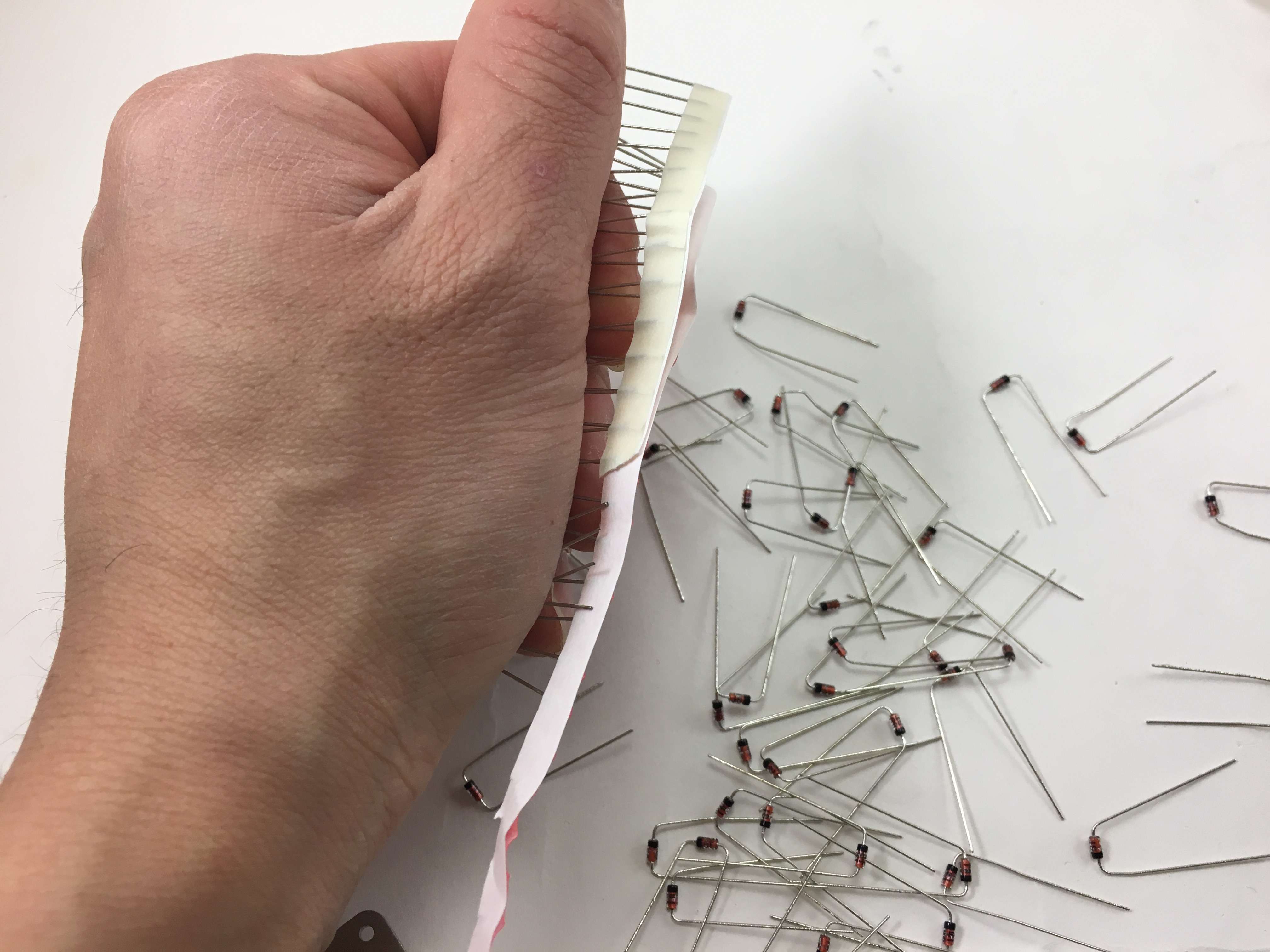
Ripping off the paper holding all the resistors together. Grip the diodes tightly so they don't bend as you're ripping the paper off.
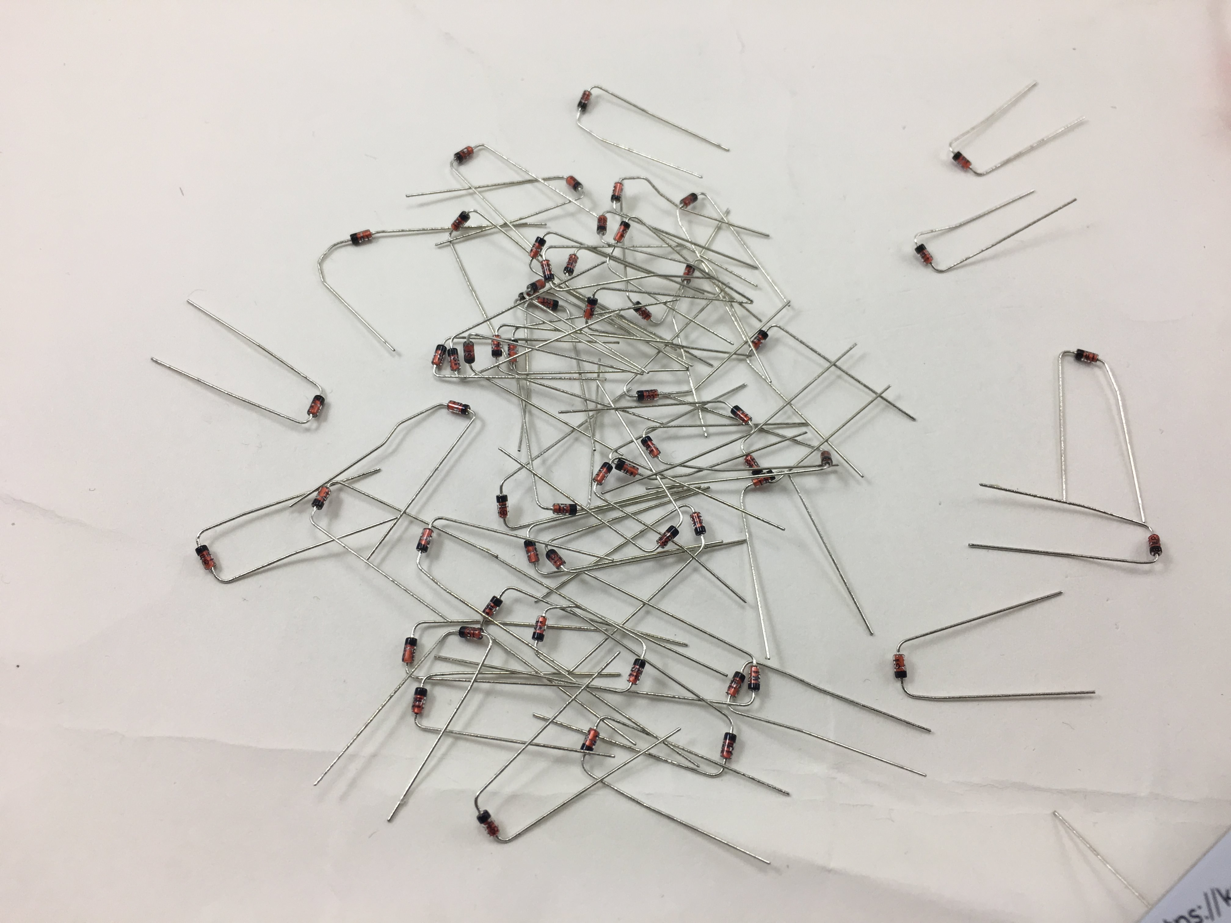
All separated from the paper
Solder Components
The diodes, resistors, MOSFETs, push buttons, TRRS jacks, and Pro Micro header pins can be soldered in any order.
Solder diodes
On the bottom side of the PCB, insert diodes with the black line towards the bottom. Square = Black line. All of the diodes are oriented vertically on the PCB: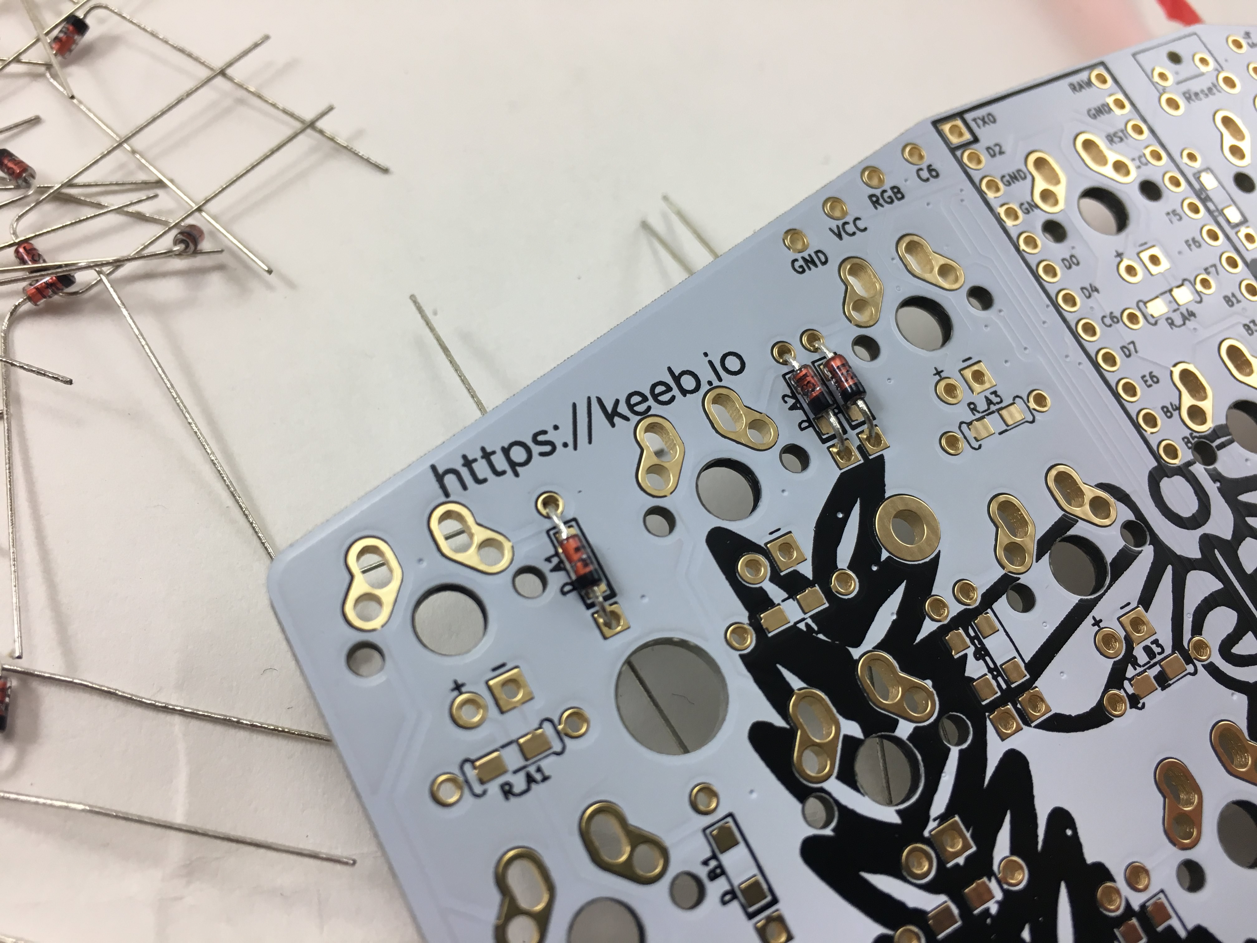
The diode orientation is flipped to move the LEDs to the north side. The black line will point towards the top on these PCBs. :::
Some people stick the diodes on the top side of the PCB, I don't recommend doing it that way, because you can't replace them once everything is assembled using that method.
Bend the legs out to hold the diodes in place for when you solder them in: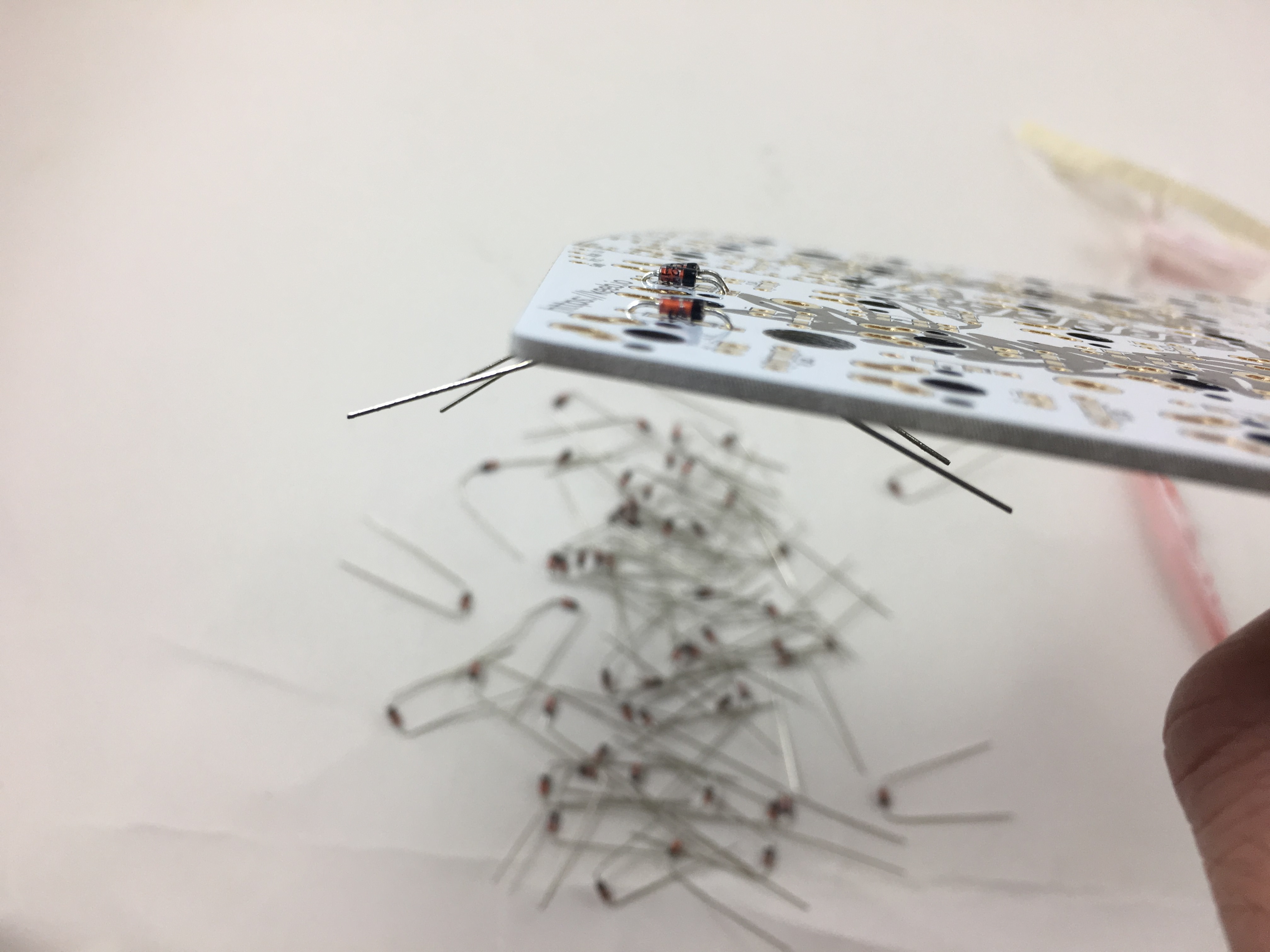
Diode insertion complete: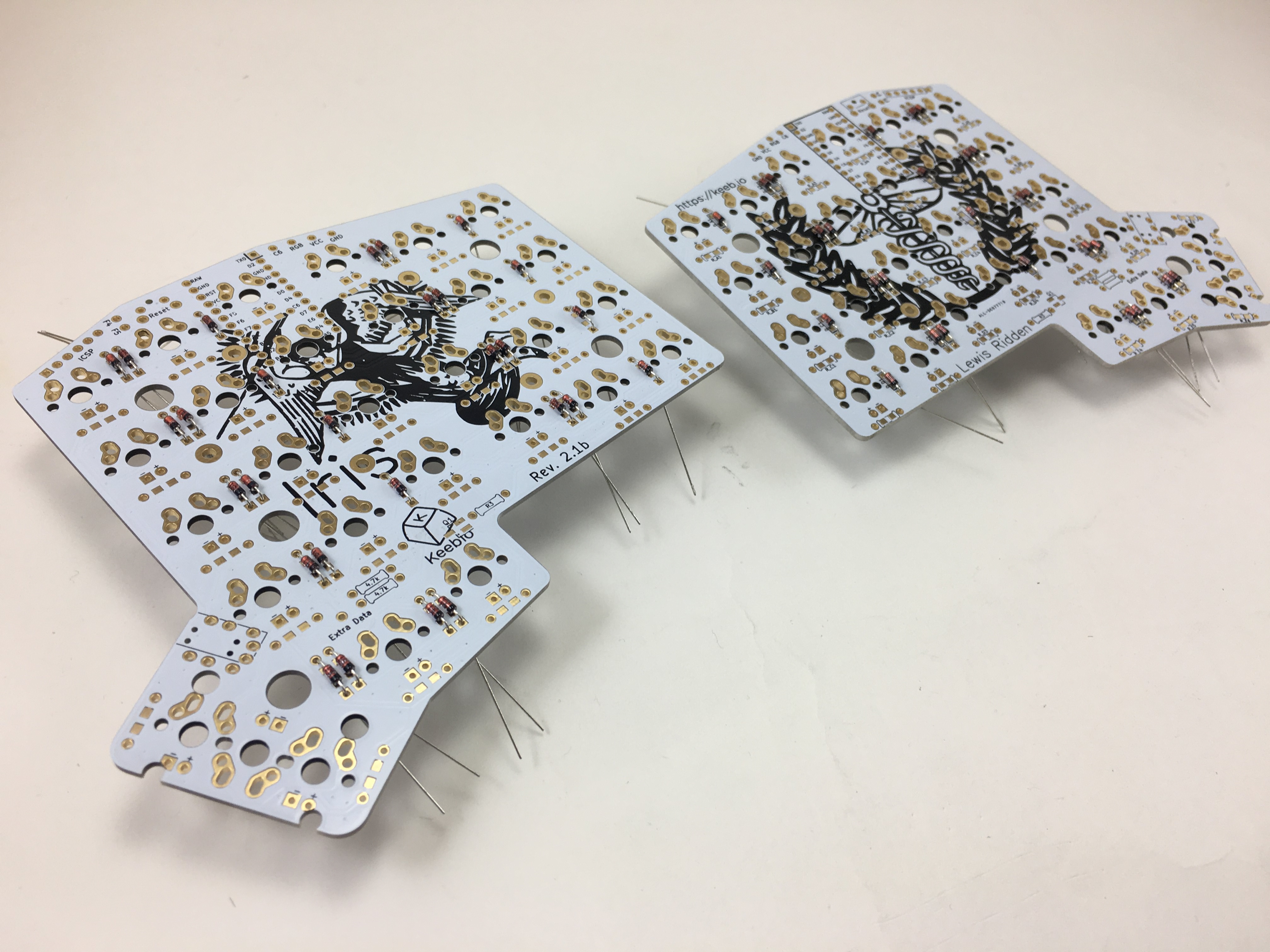
Left PCB: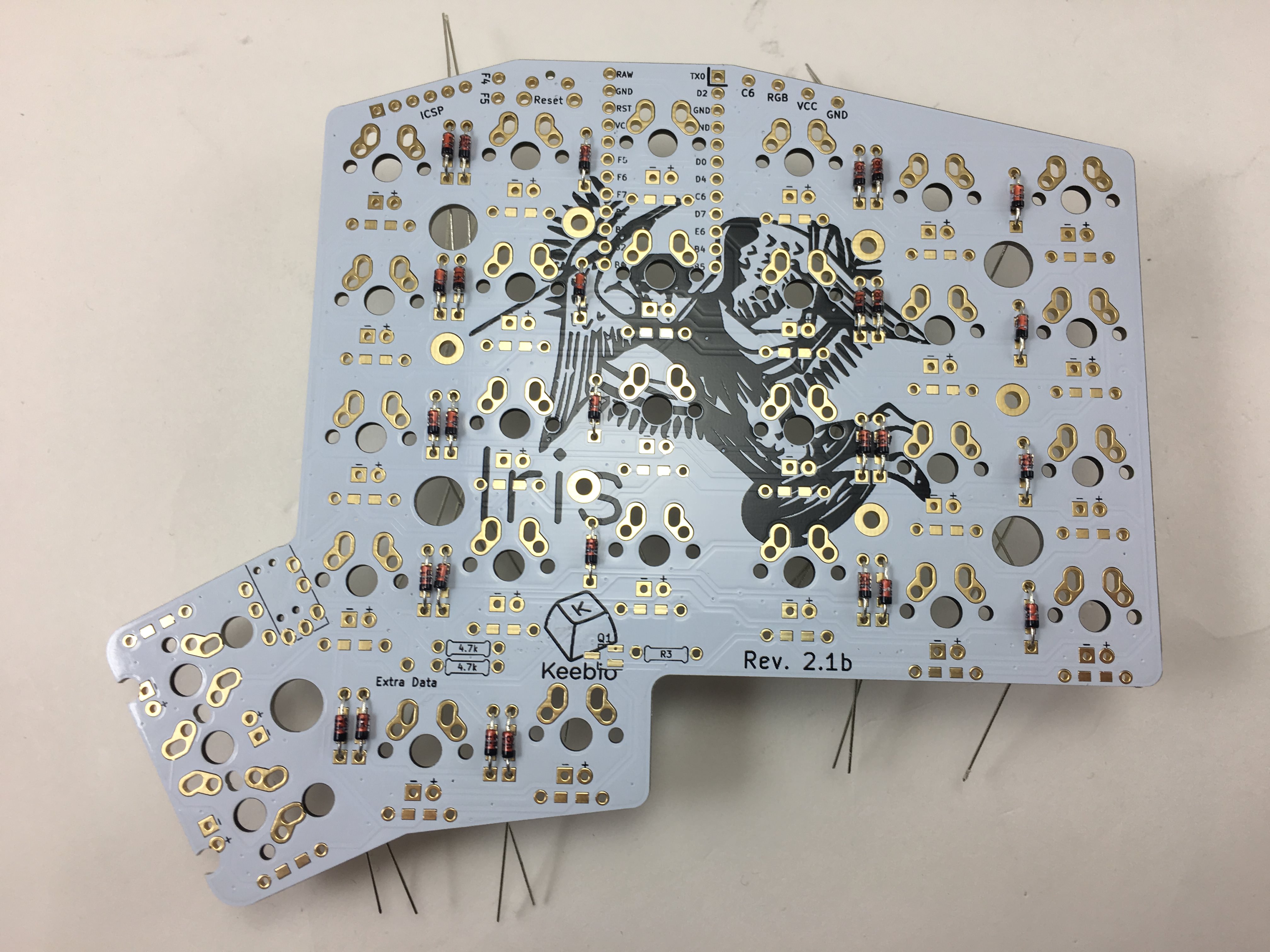
Right PCB: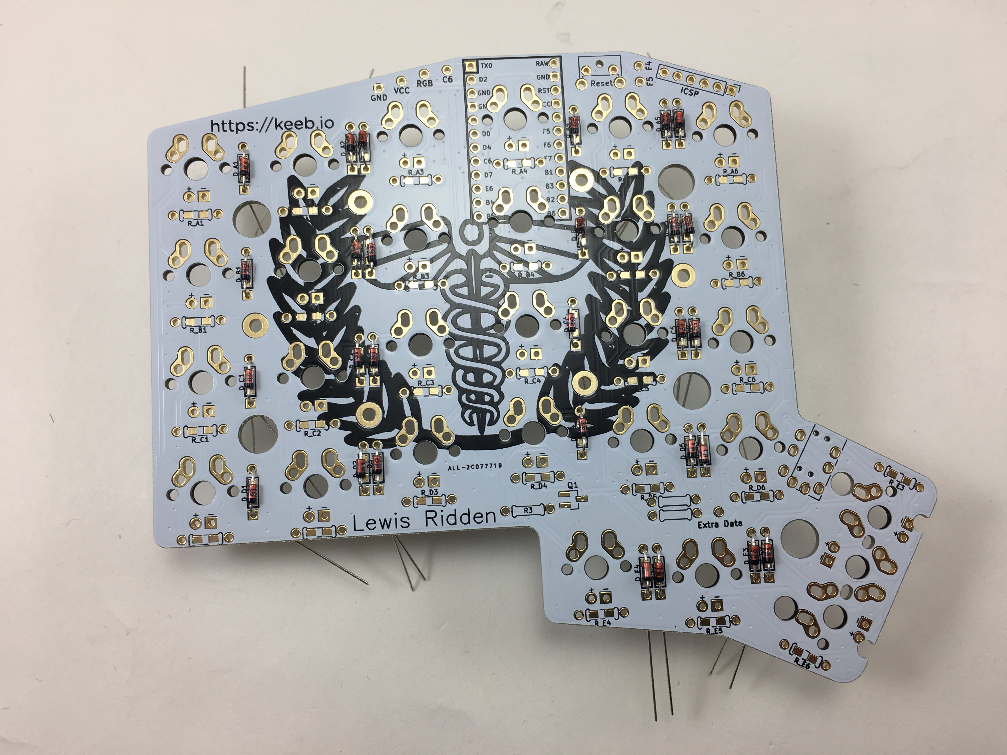
Solder reset push buttons and TRRS jacks
Add the TRRS jacks and reset switches: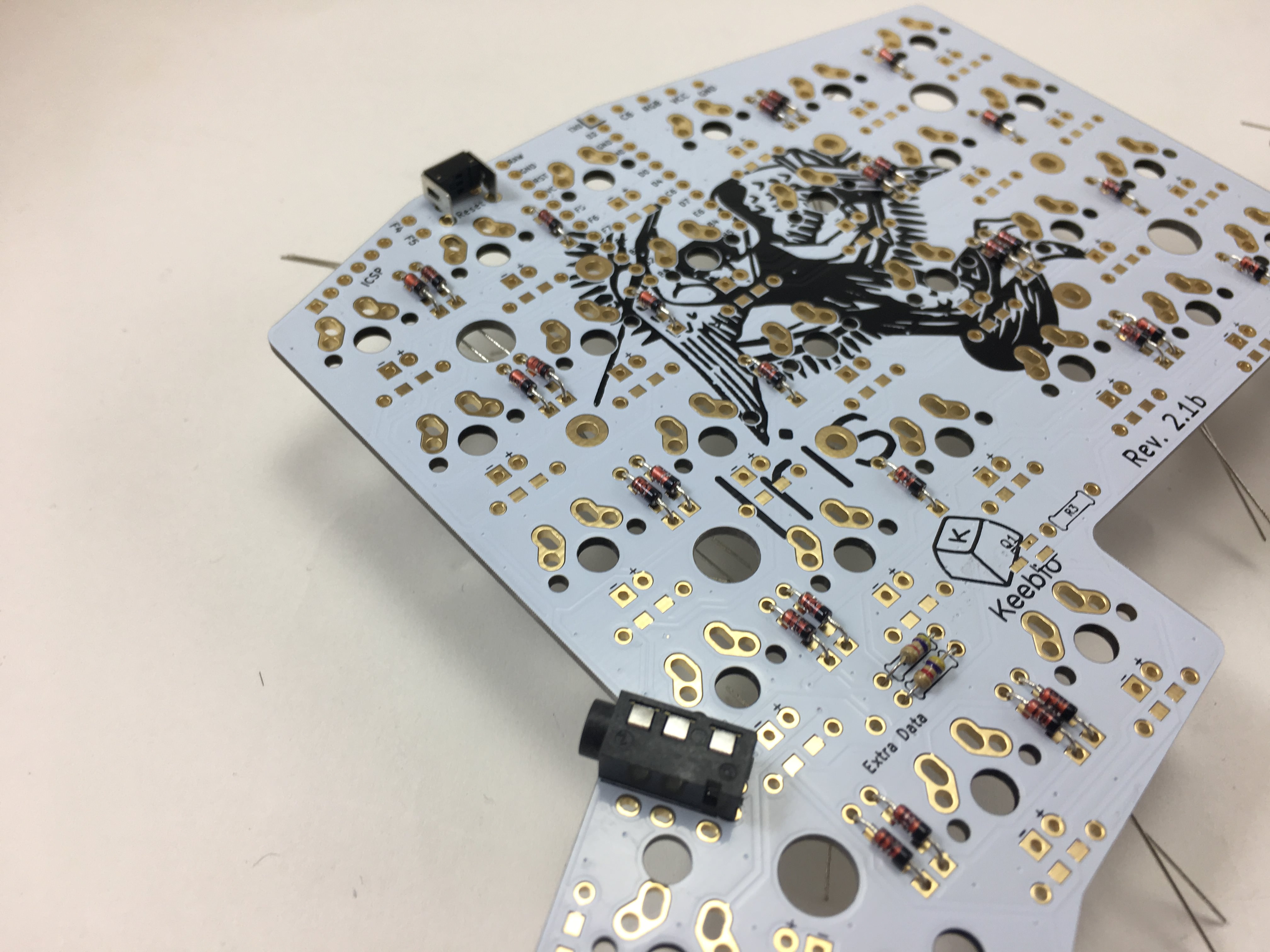
Solder I2C resistors (optional)
The default firmware for the Iris uses serial communication between the two halves using a single pin of the TRRS cable. Serial communication only allow for communication between two parts, which is fine for almost all builds.
However, in the future, there might be additional parts that you can add, like a numpad, OLED screen, etc. To support this, the communication protocol would need to be switched over I2C, which can support multiple devices. To add support for I2C, all you need to do is add the 2 4.7kΩ resistors to one of the halves (other half does not need them). Also, it doesn't hurt to add these resistors if using serial communication.
tl;dr: Adding this is optional, but you might as well do it as it's only 2 more components to solder.
Add the 2 4.7kΩ resistors for I2C on only one half (I normally do this on the master/left half). Left half shown here: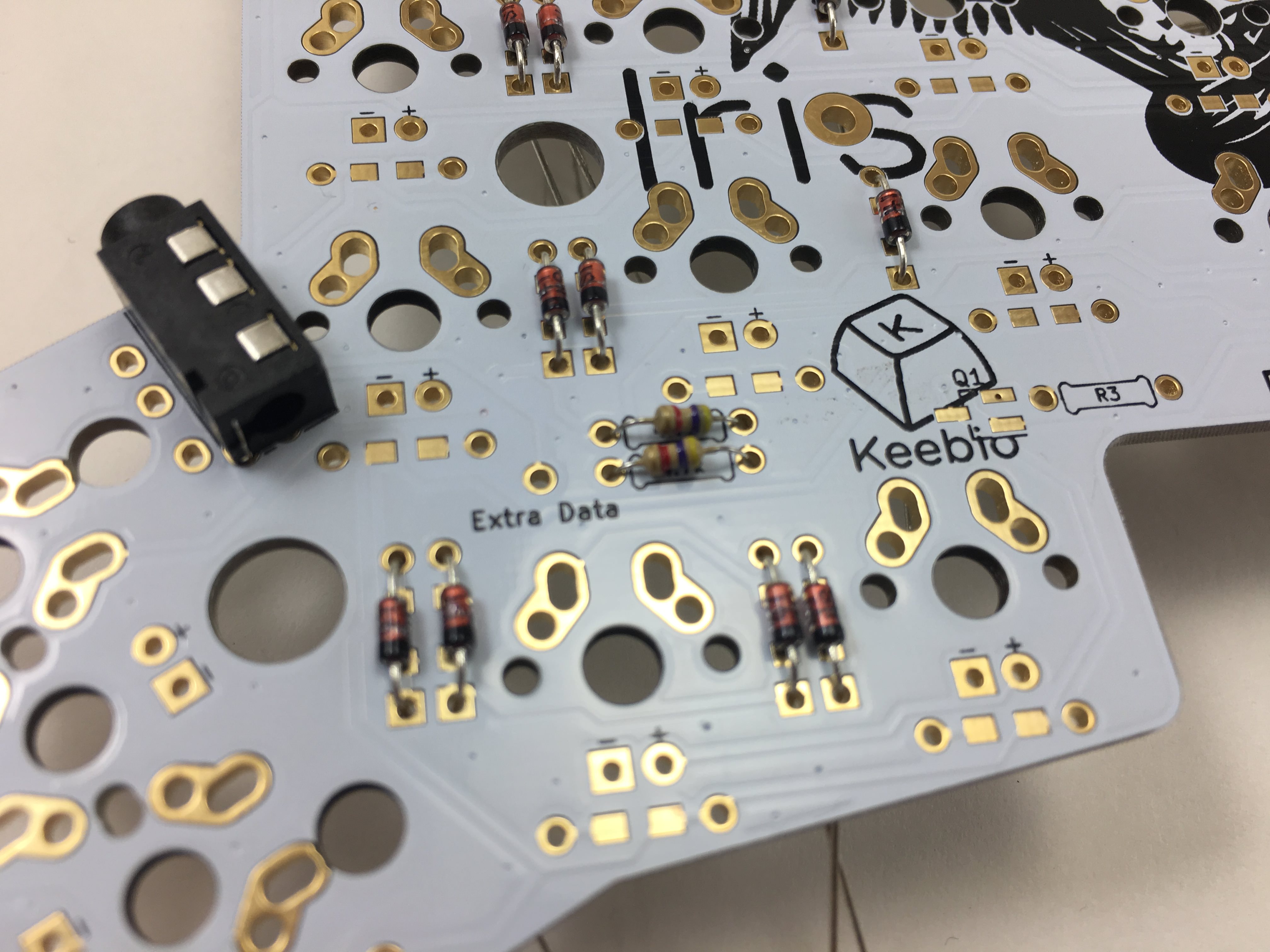
Solder LED support components (optional)
Add a 4.7kΩ resistor for LED support in the R3 slot: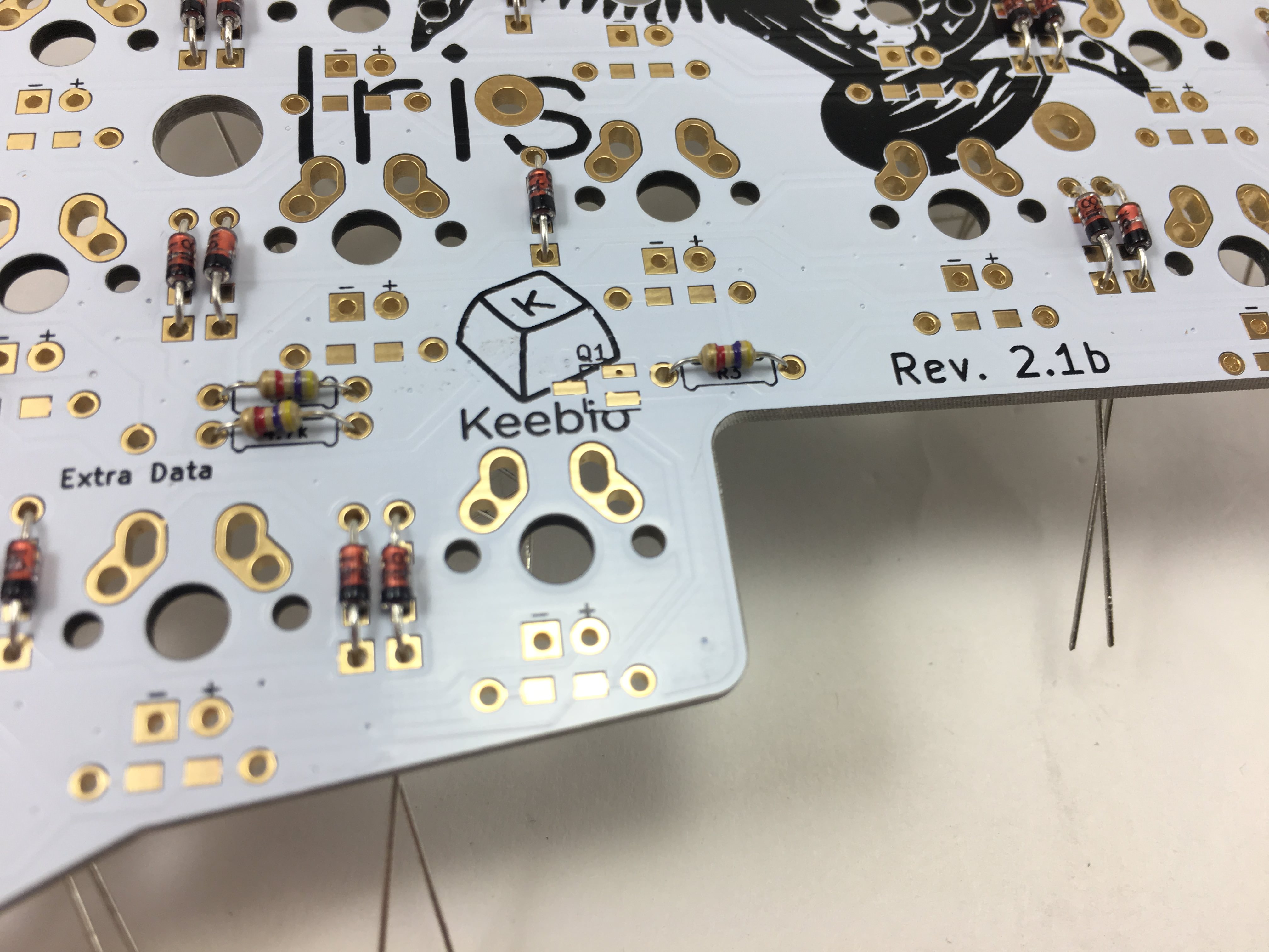
Add 470Ω resistors for LEDs. Resistors don't have polarity, so orientation doesn't matter. Note that the resistor that's seated with the Pro Micro has been inserted on the top side of the PCB, which prevents it from touching the Pro Micro. (This resistor will be relocated out of the way in future versions of the PCB). Left side shown here: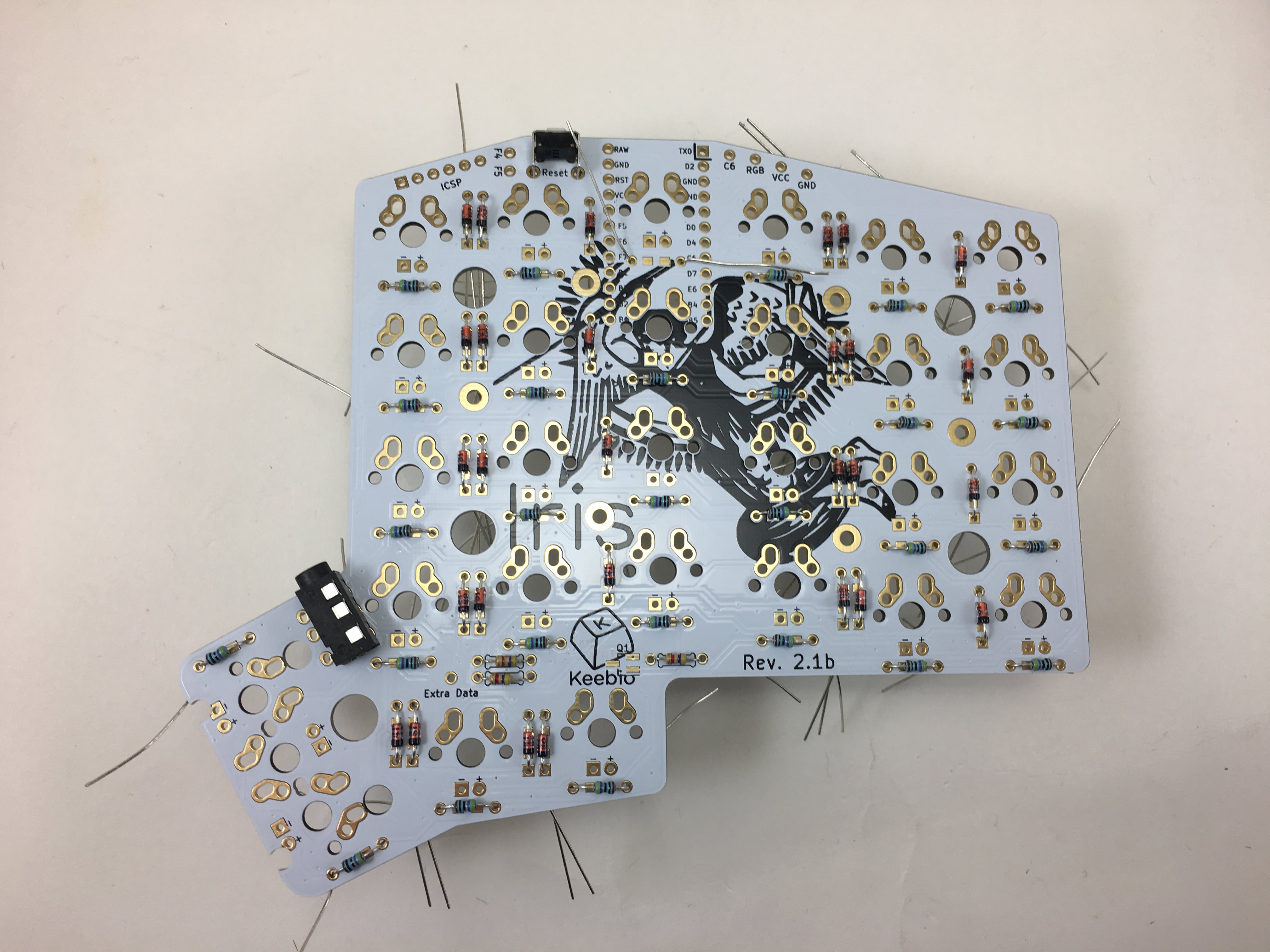
Right PCB: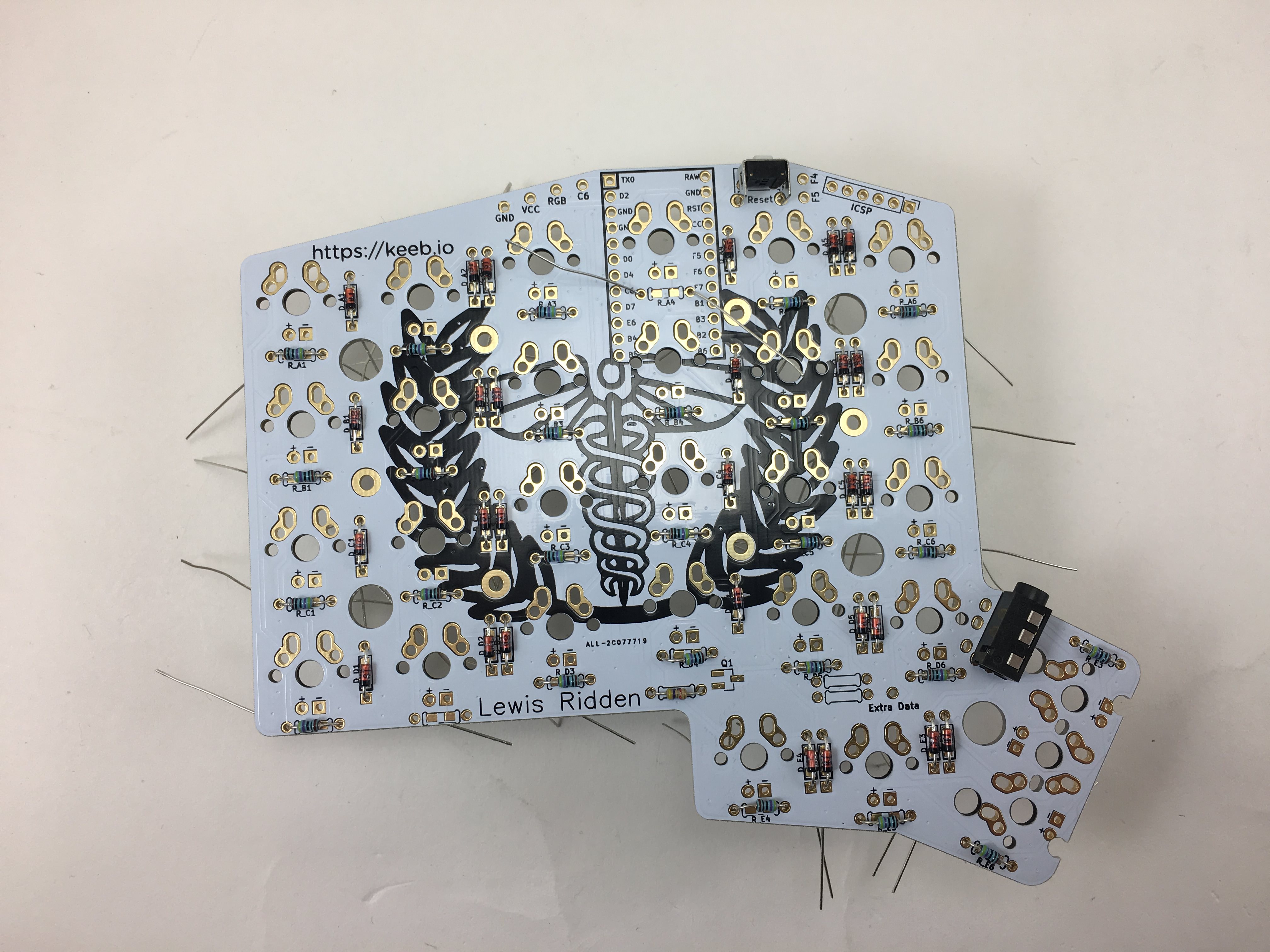
There's a missing trace/via on one of the pads for the MOSFET of the right half (the one shown here). To resolve this, solder the MOSFET to the other side of the board, as the pads for those are fine. (Issue has been fixed on Rev. 2.5 PCB). If you do happen to solder the MOSFET to this side by accident, you can perform this fix to resolve the issue: Iris 2.1b/2.4 LED MOSFET Fix
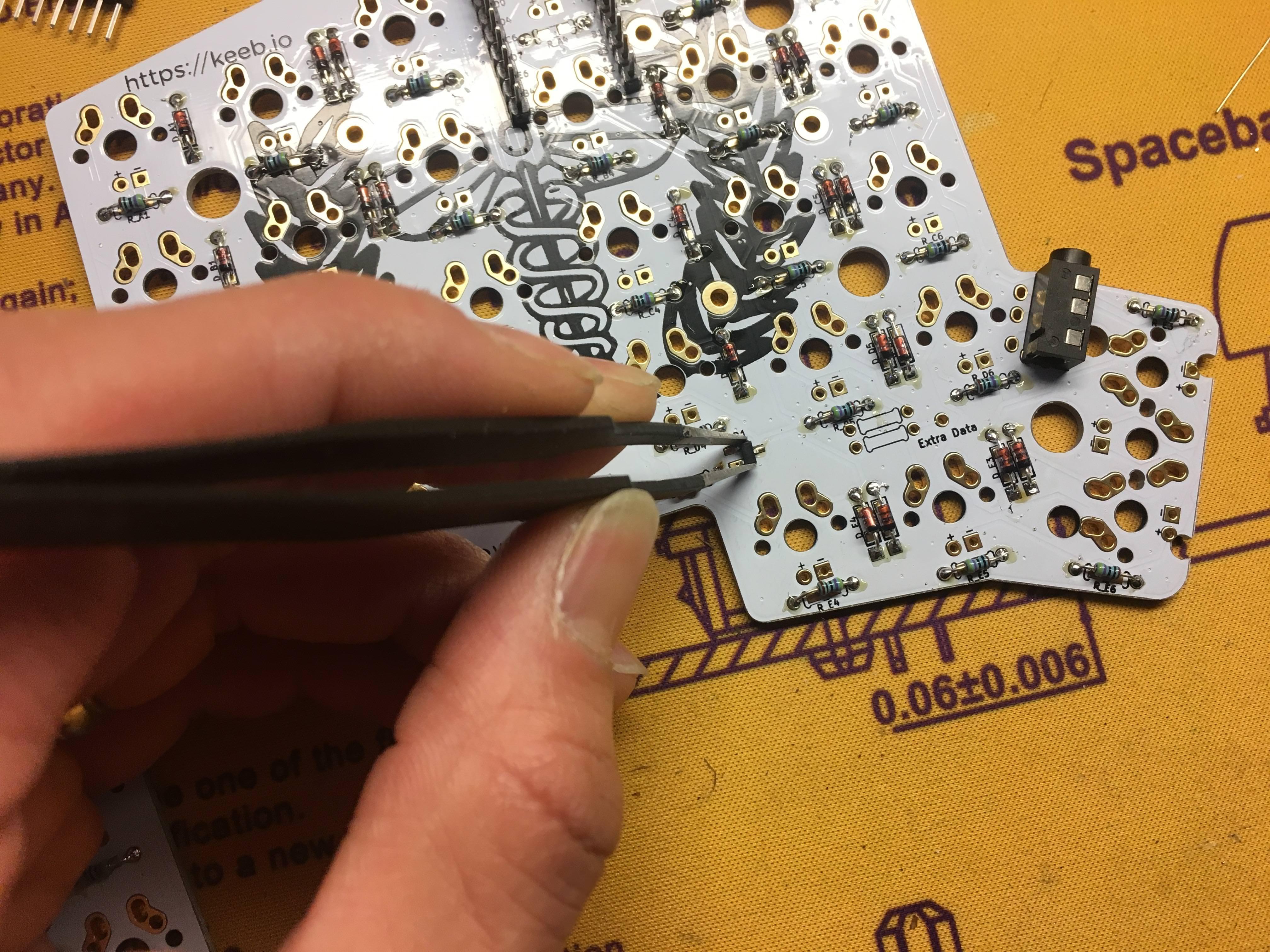
To add the MOSFET, tin one of the pins on the PCB first: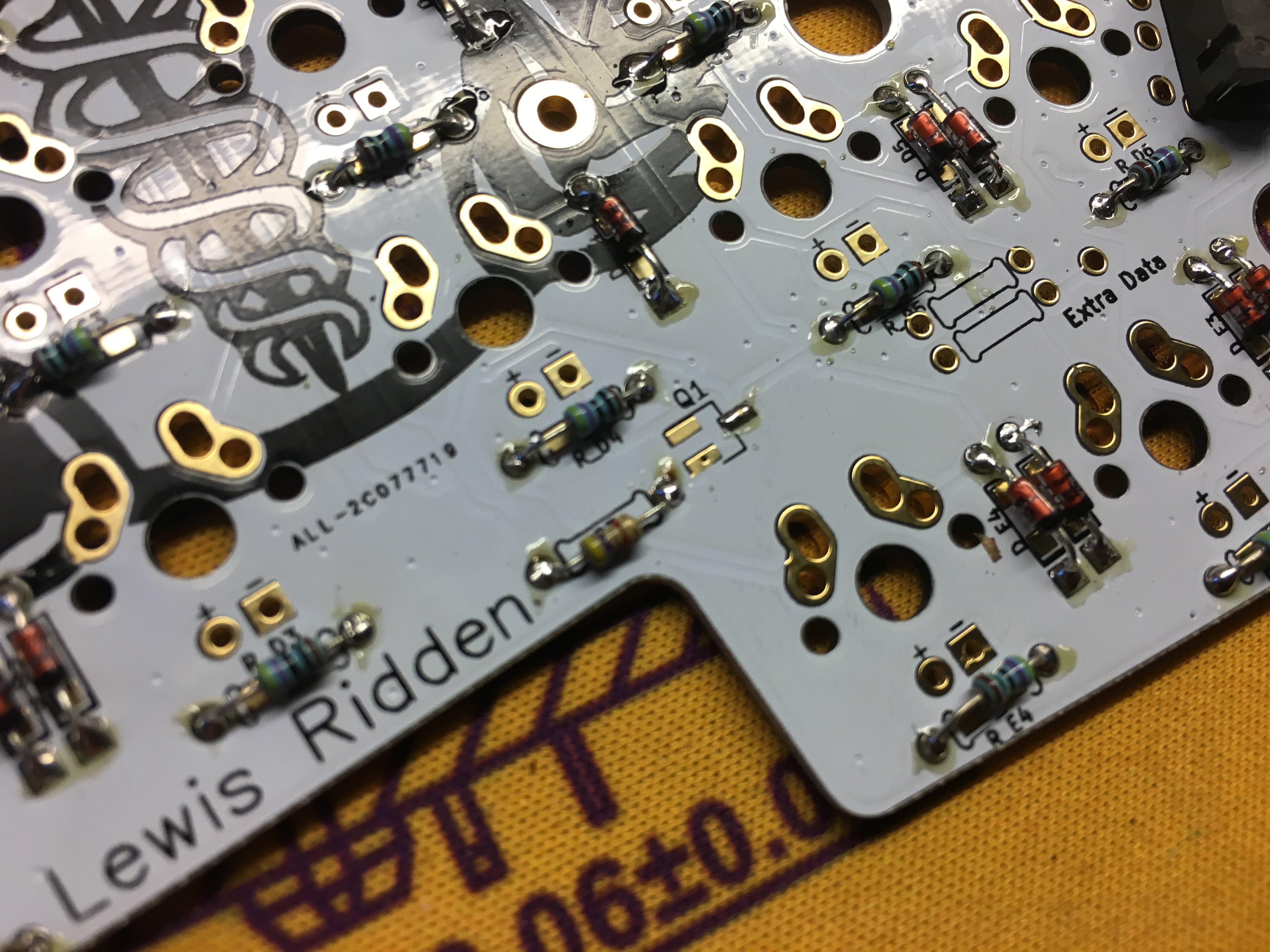
Hold the MOSFET with a pair of tweezers and align it over the footprint. Then solder the first pin:
Once you're satisfied with the alignment, solder the other 2 pins: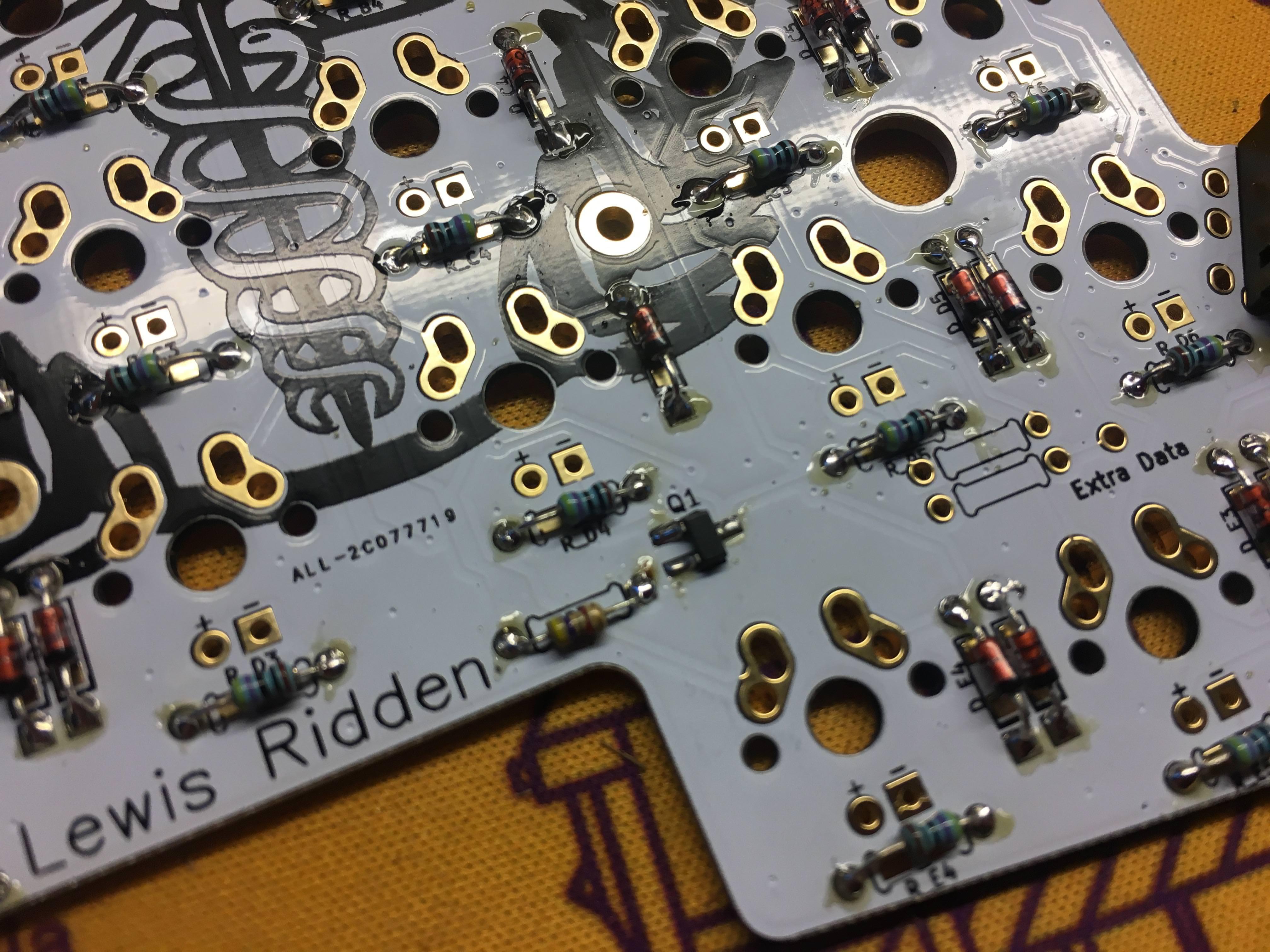
Repeat the MOSFET installation process on the other PCB: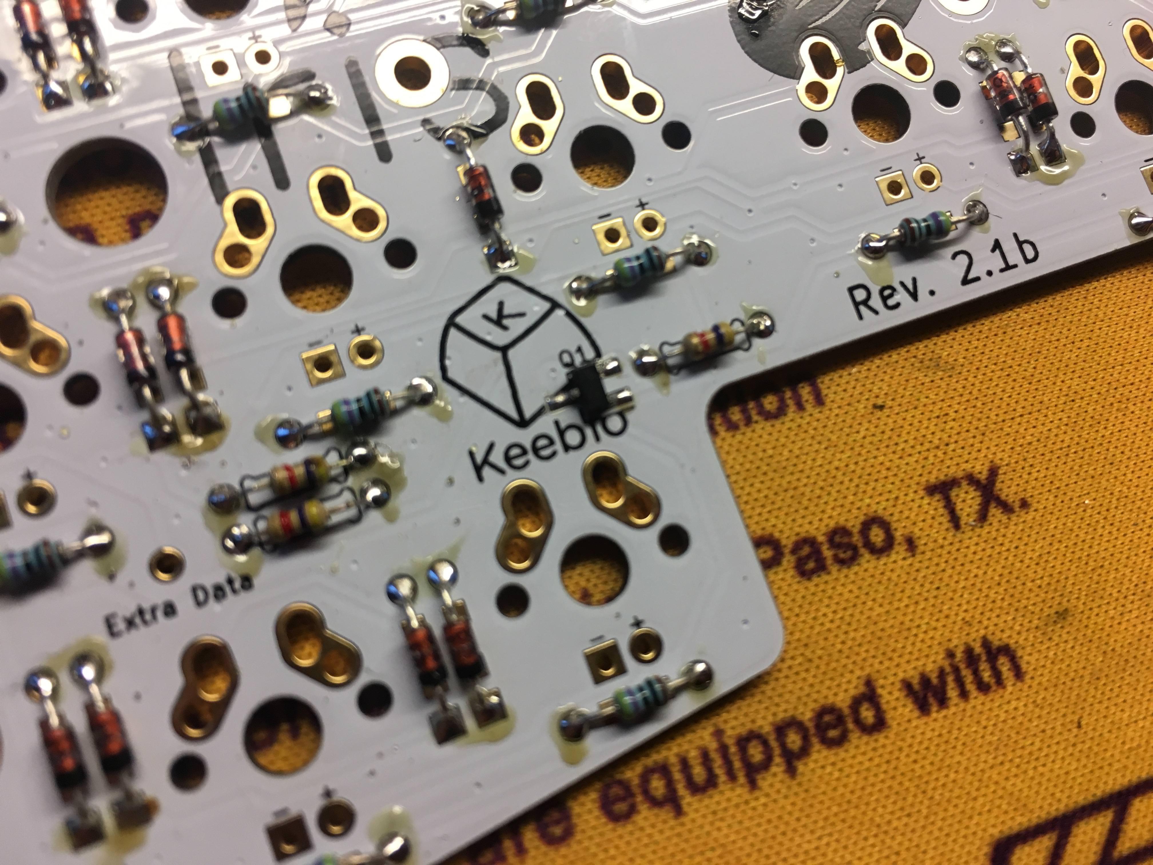
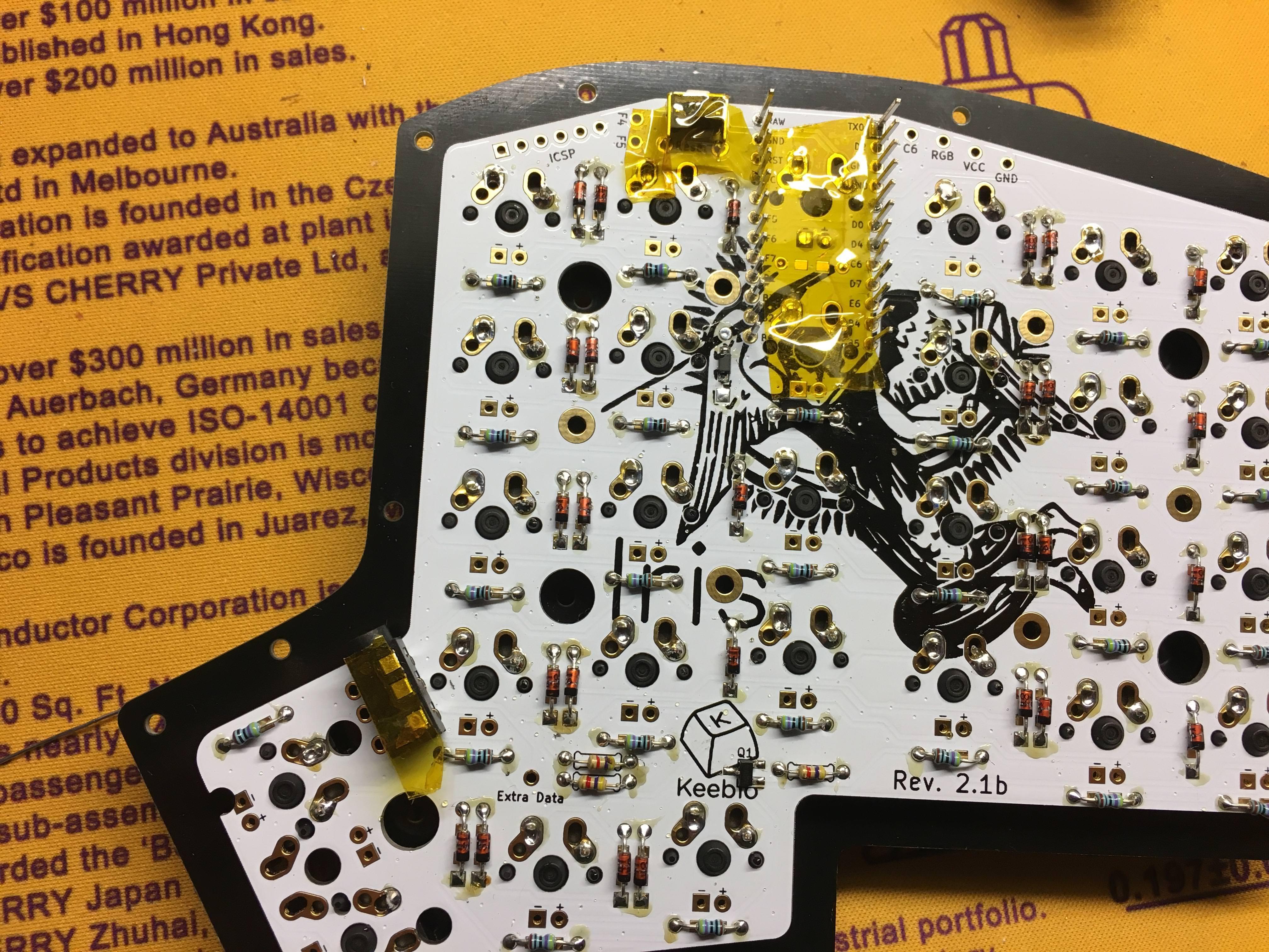
Solder Pro Micro header pins
Install the header pins for the Pro Micro on the underside of the PCB (left PCB shown). You can use some tape to hold the header pins in place while soldering. Solder one pin on and re-adjust/re-solder as needed before doing the rest of the row: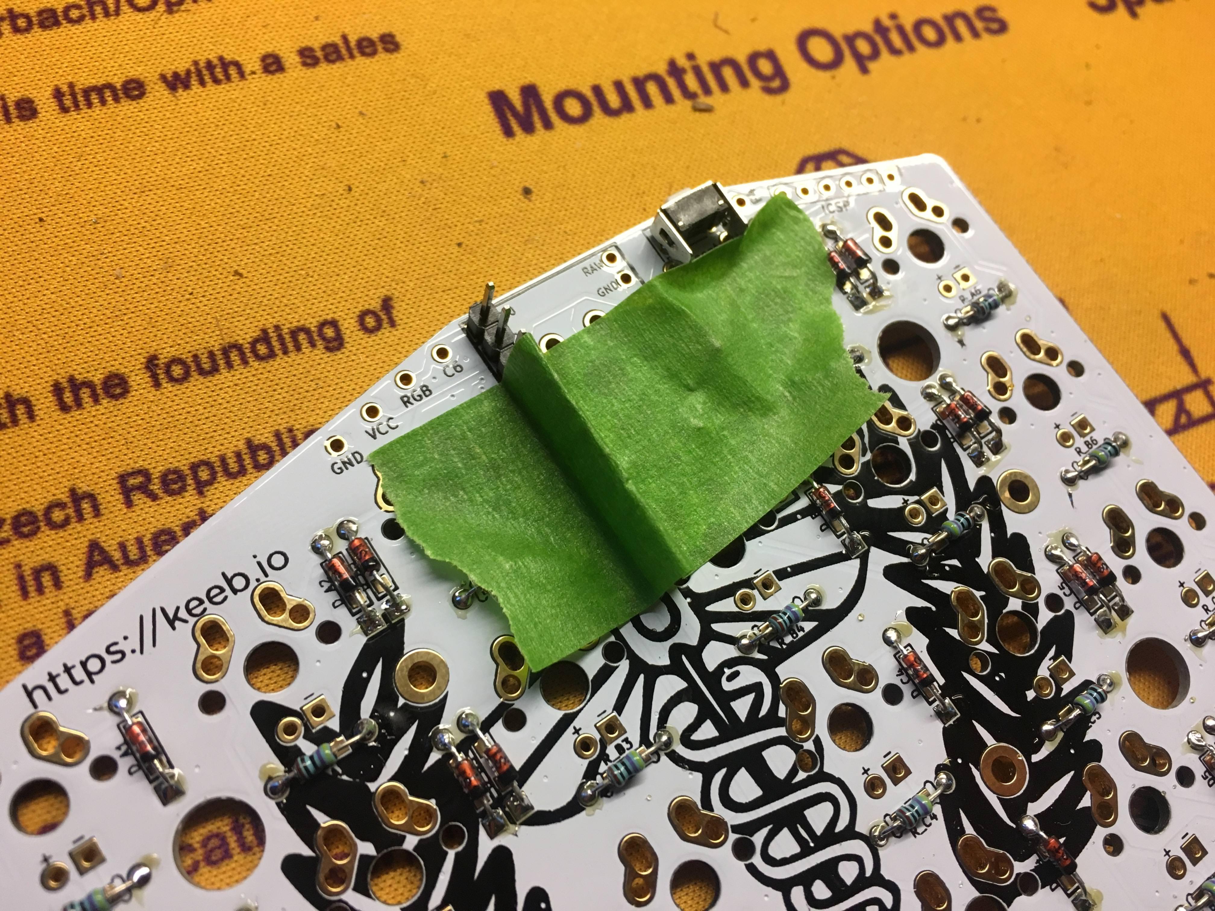
Completed right PCB: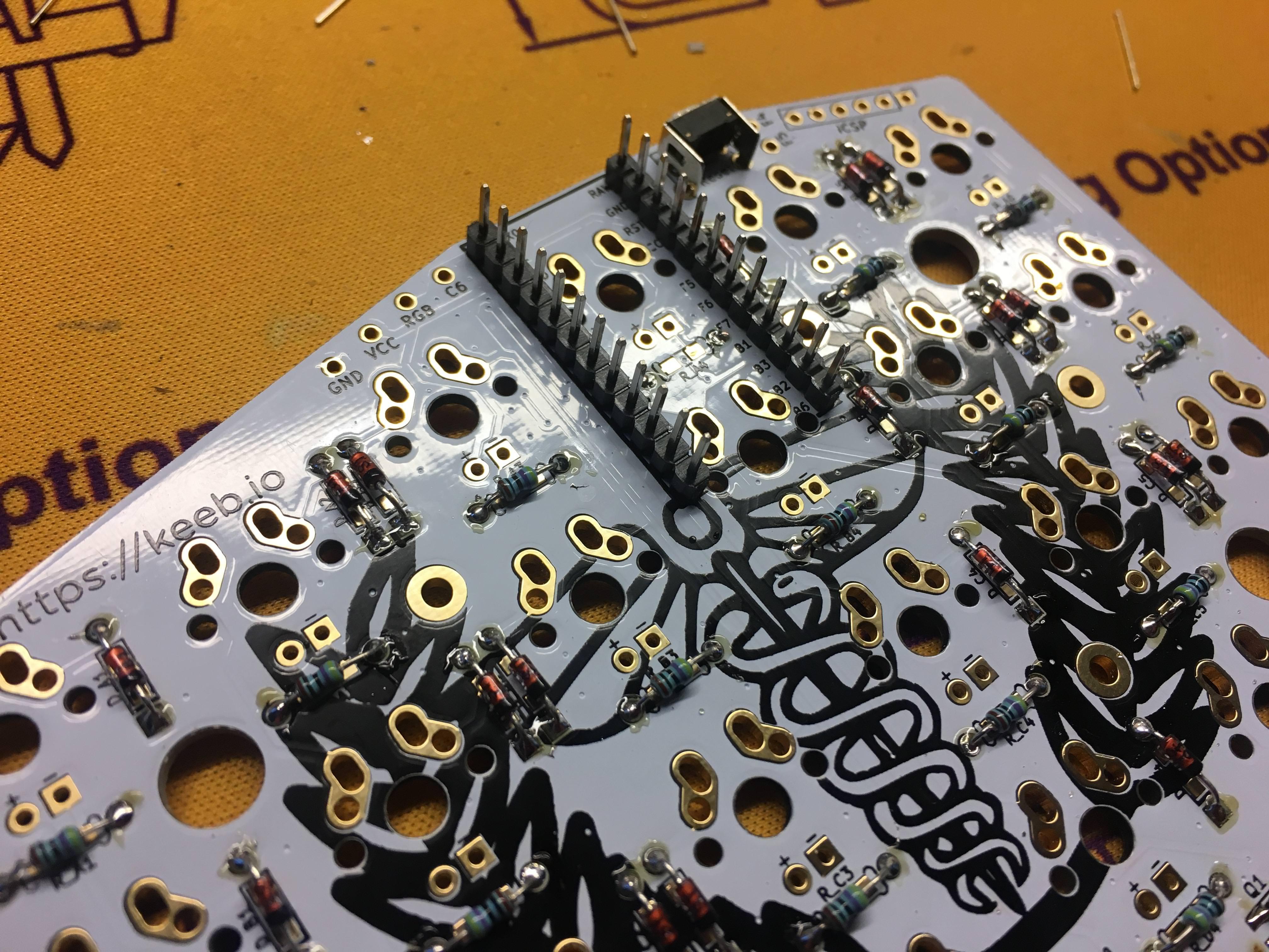
Left PCB shown: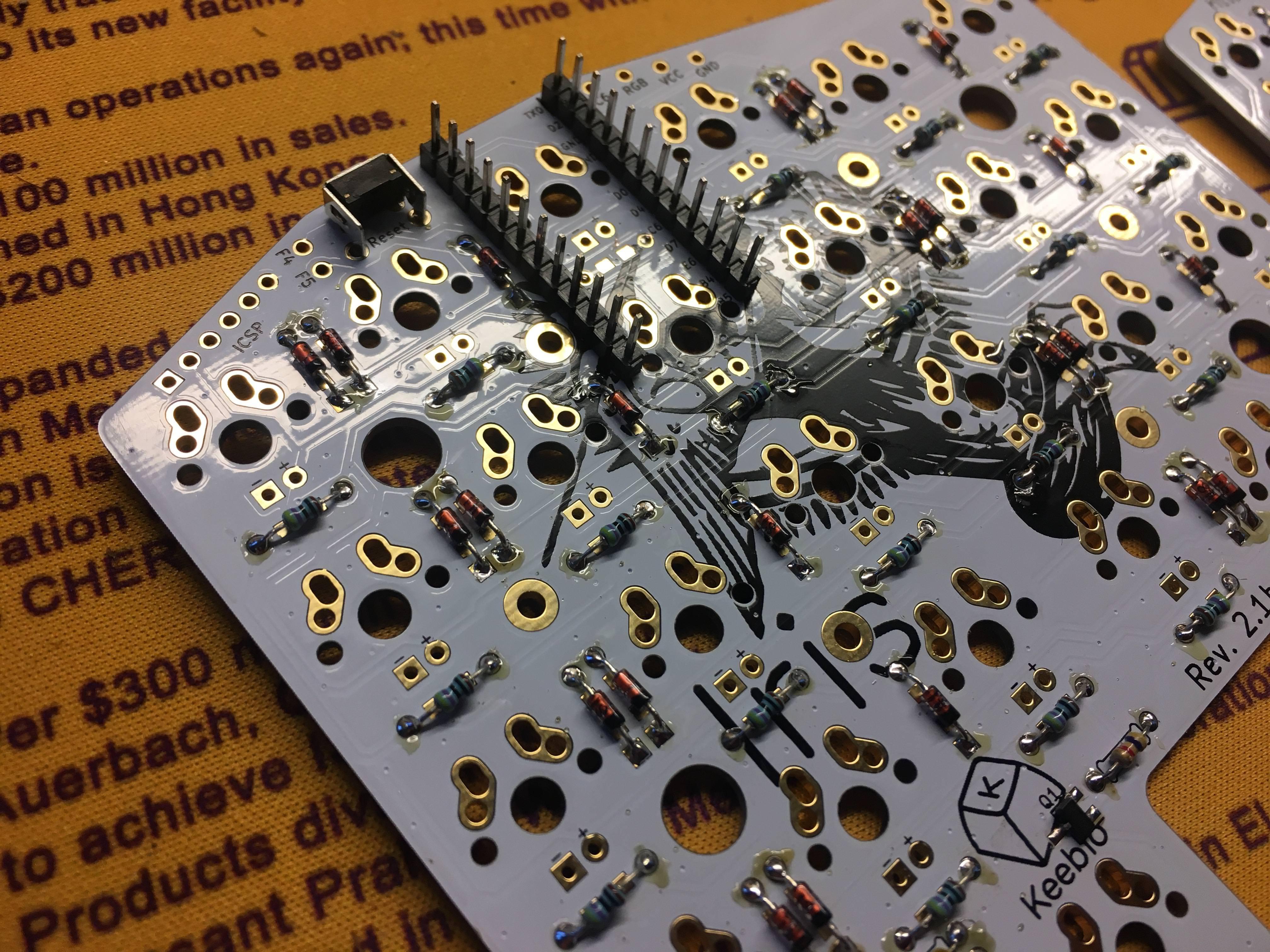
Add 2u stabilizers (optional)
Add the 2u stabilizer if desired. Do this before installing the switch plate and switches: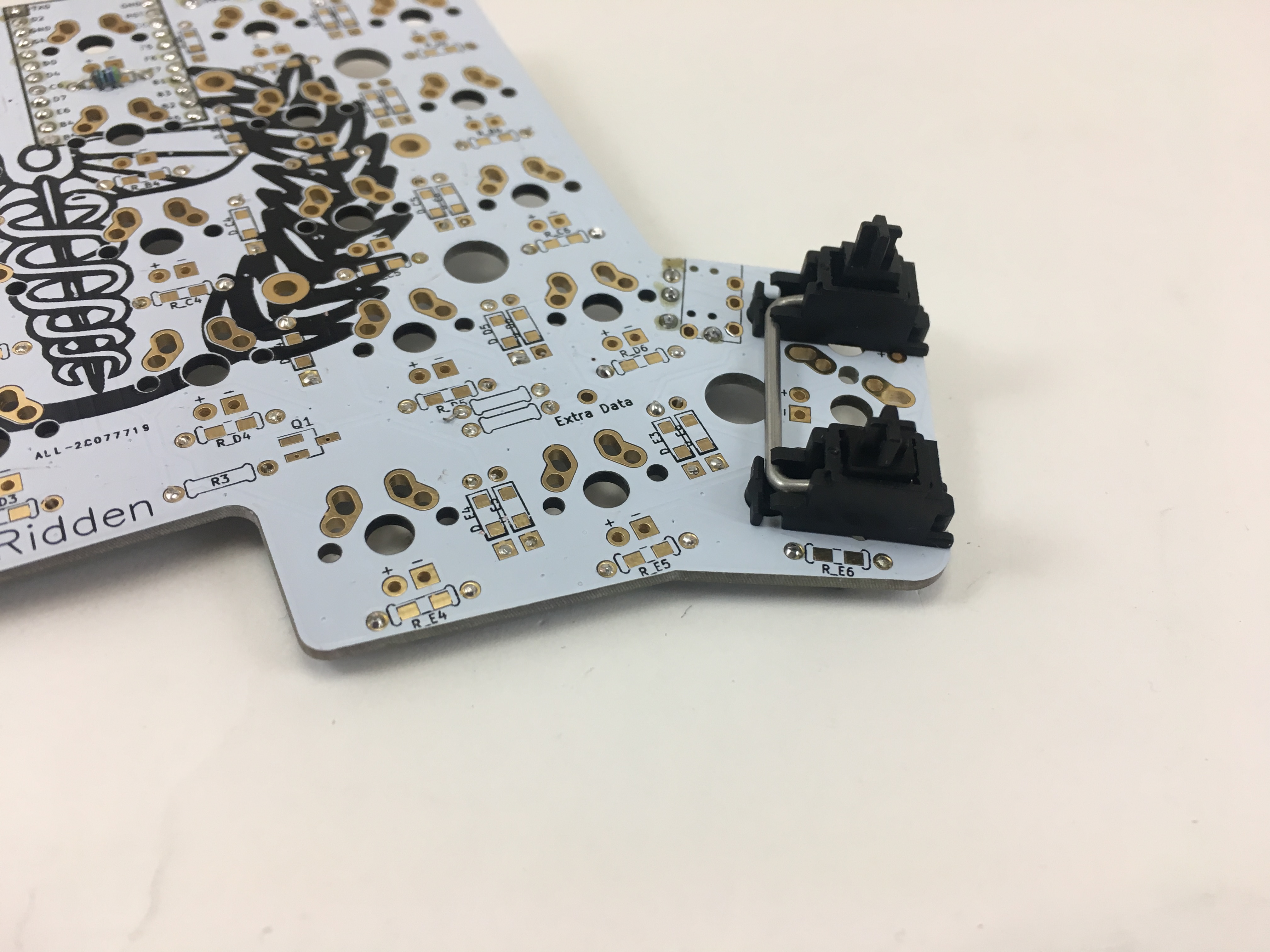
Solder switches
You will not be able to install the switch plate after soldering the switches, as the switches need to go on top of the switch plate.
Add switches into the switch plate. Usually, I add switches to the corners first and then solder them before installing the rest of them: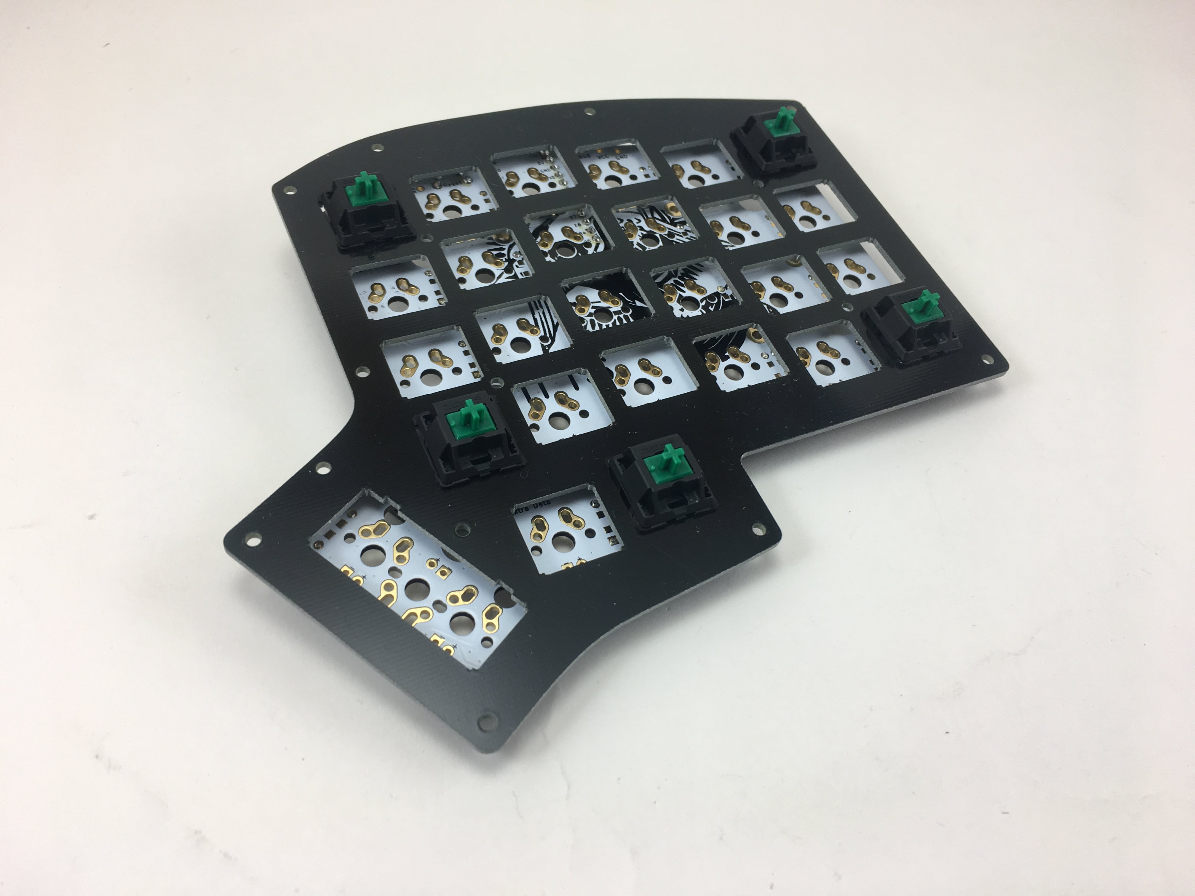
All installed: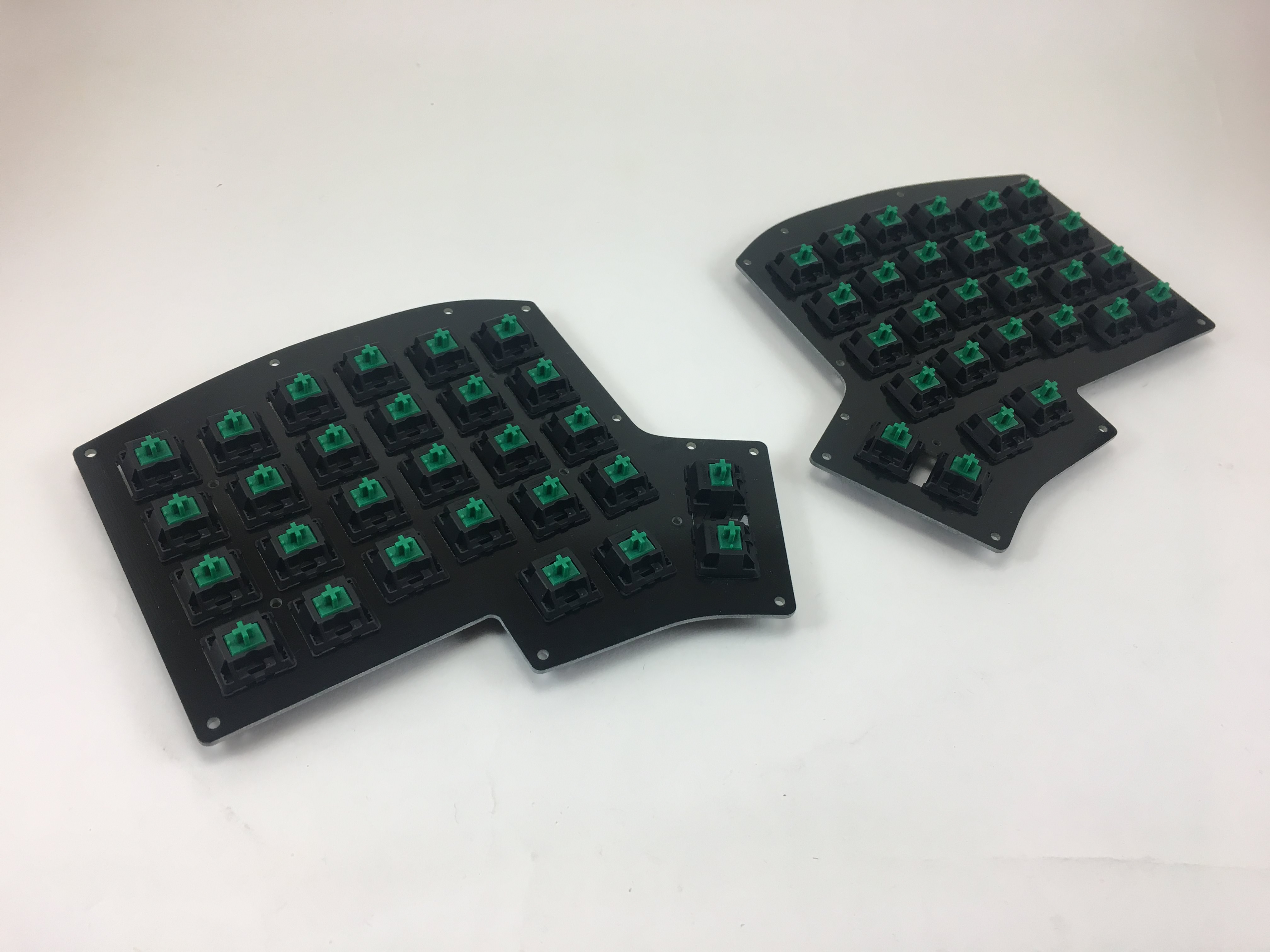
Solder LEDs
Install the LEDs. Longer leg is the anode and goes with the circular pad marked with +. The shorter leg is the cathode and goes with the square pad marked with -: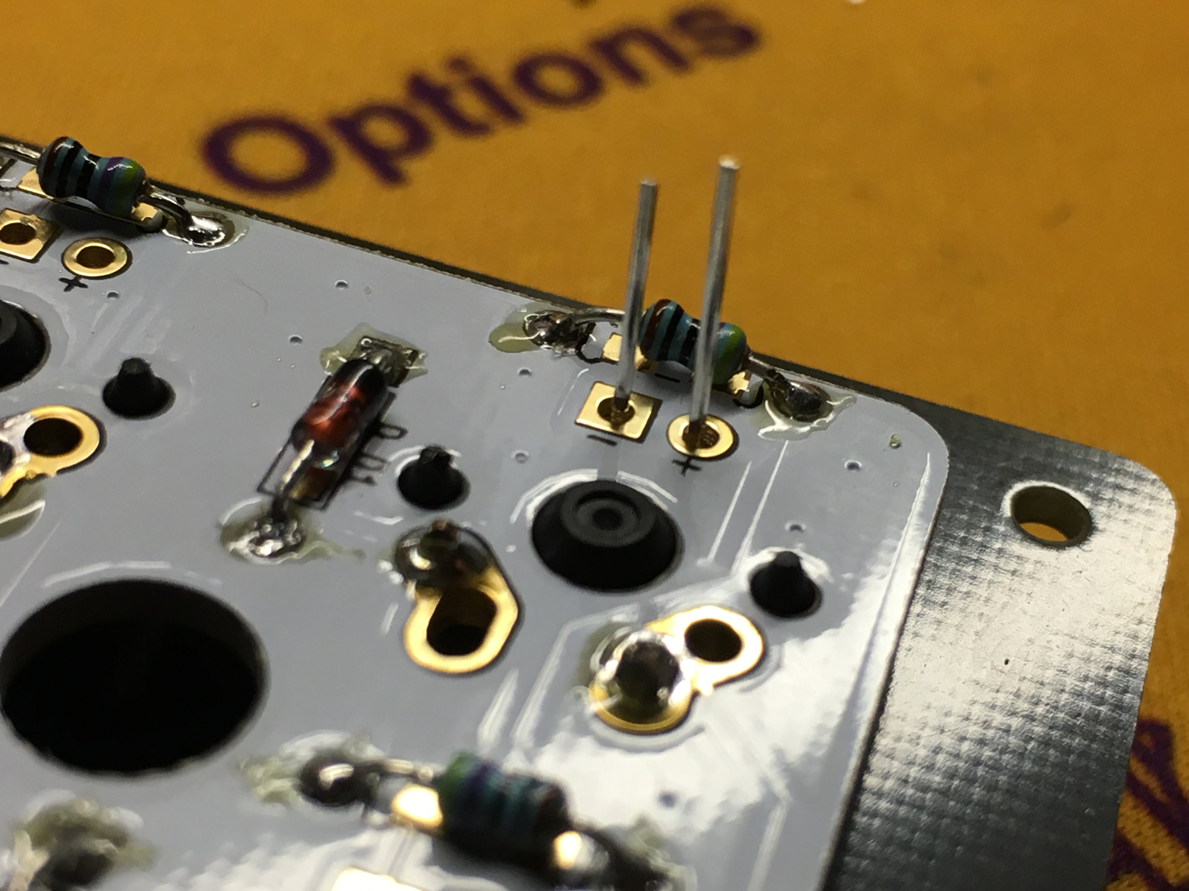
I normally pry off the plastic parts of the header pins to made the Pro Micro sit more flush with the PCB. An added benefit of this is that the Micro USB port for the left half is sandwiched between the Iris PCB and the Pro Micro PCB, making it less likely to be ripped off.
Trim down the switch pins, LED pins, and resistor pins that the Pro Micro will sit on top of with a flush cutter: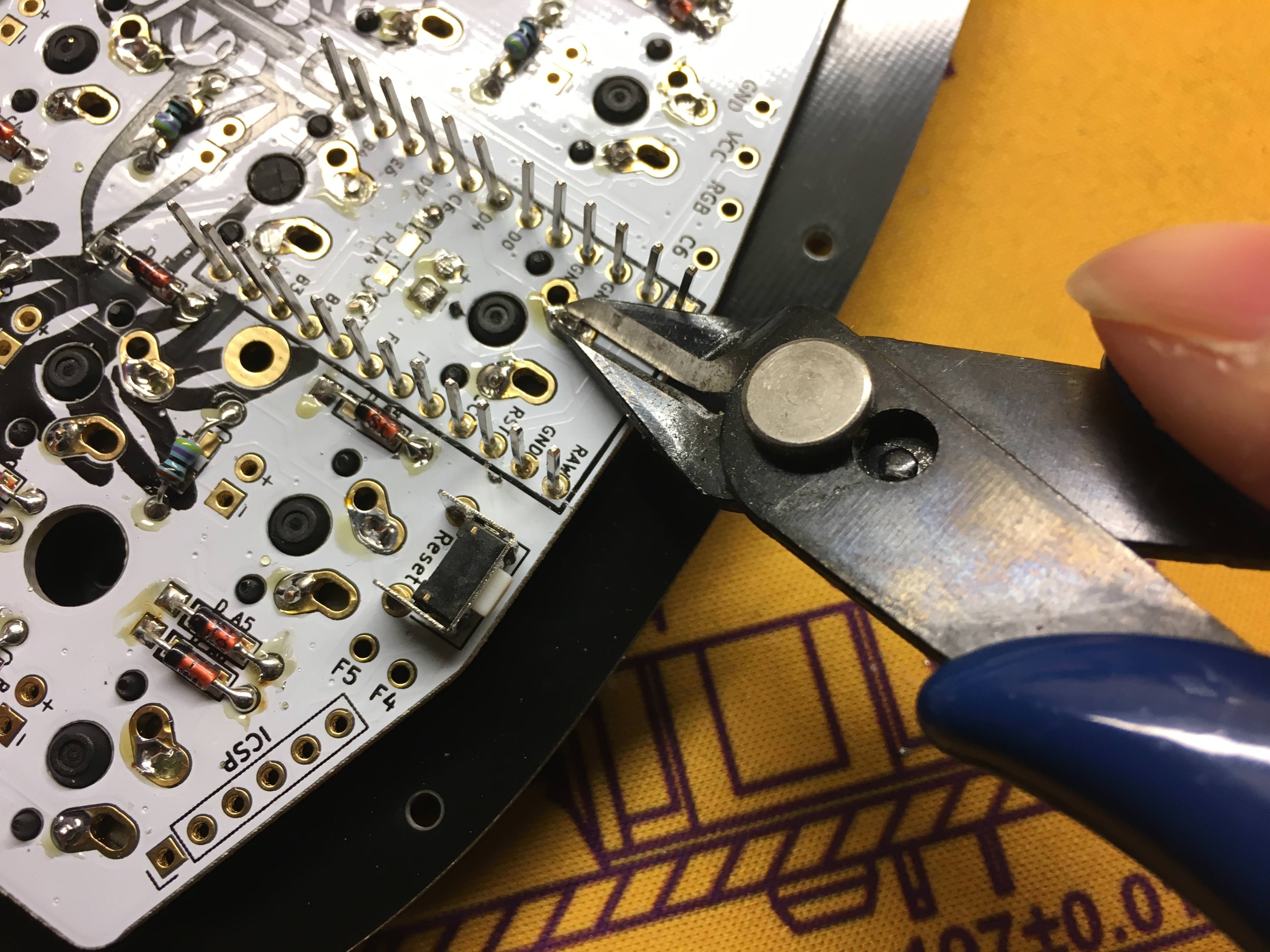
Flash Pro Micros
The last thing to install is the Pro Micros. Before soldering them to the board, it is highly recommended to flash them first, in case one or both of them are defective.
Refer to the Flashing Firmware Guide for steps on performing a flash to test the Pro Micro controllers.
Solder Pro Micros
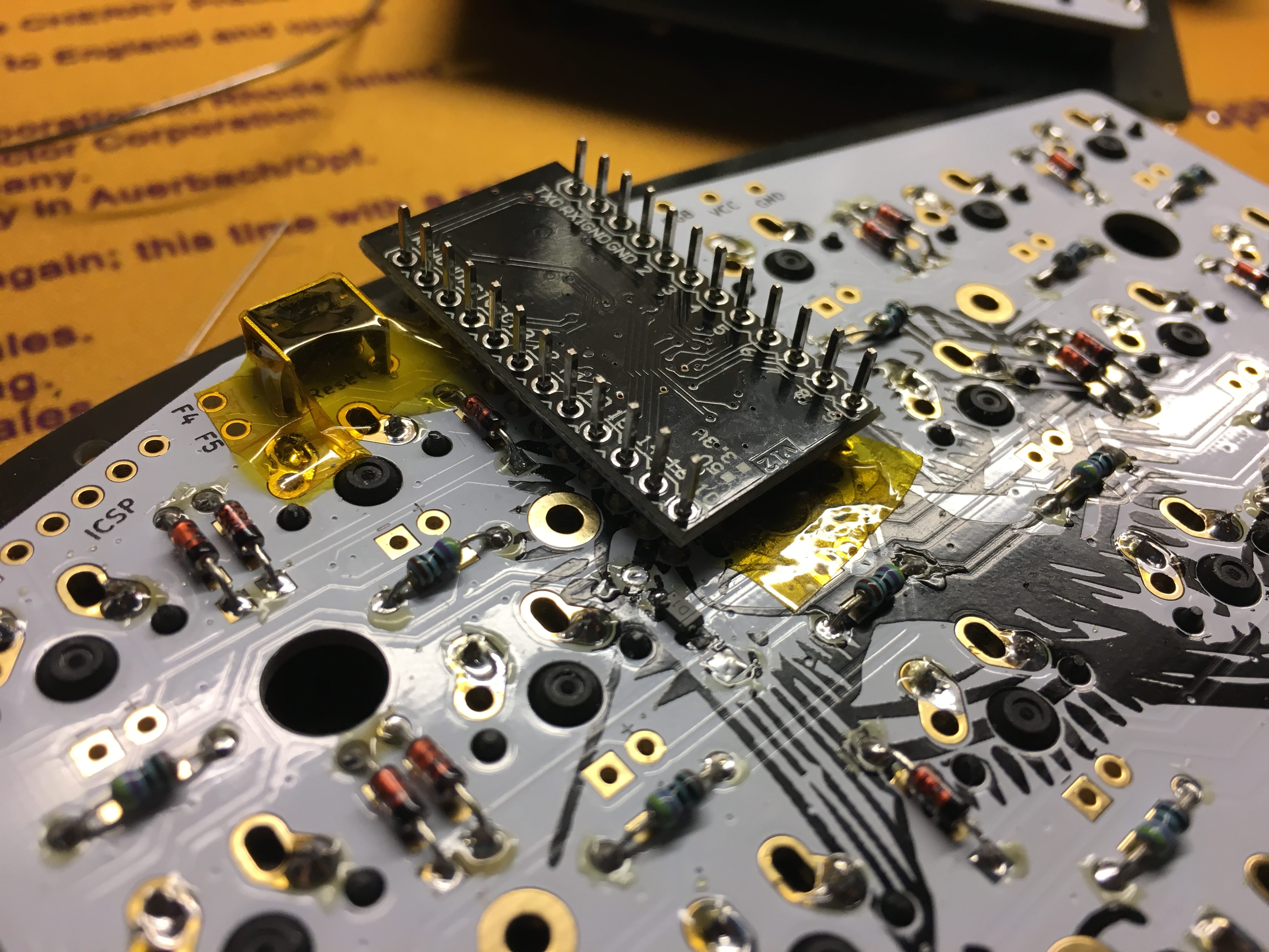
If using a bottom plate that conducts electricity, like a stainless steel or aluminum plate, add Kapton or electric tape on top of the TRRS jack. Also put some down where the Pro Micro will be:
Set the Pro Micro through the pins, making sure RAW and TX0 are aligned properly with the markings on the PCB. The orientation on both PCBs is different. (Left half shown here):
TRUTH: This is totally not the case, so pay attention! Soldering the Pro Micro on backwards will short VCC and Reset together, preventing you from flashing. Even if flashed beforehand, it will do nothing meaningful in this orientation.
Both of the Pro Micro boards are oriented the same way (flat side towards you), unlike the Iris. Make sure you match up the PCB markings to confirm. Ignore the images of the Iris Right half here.
Right half: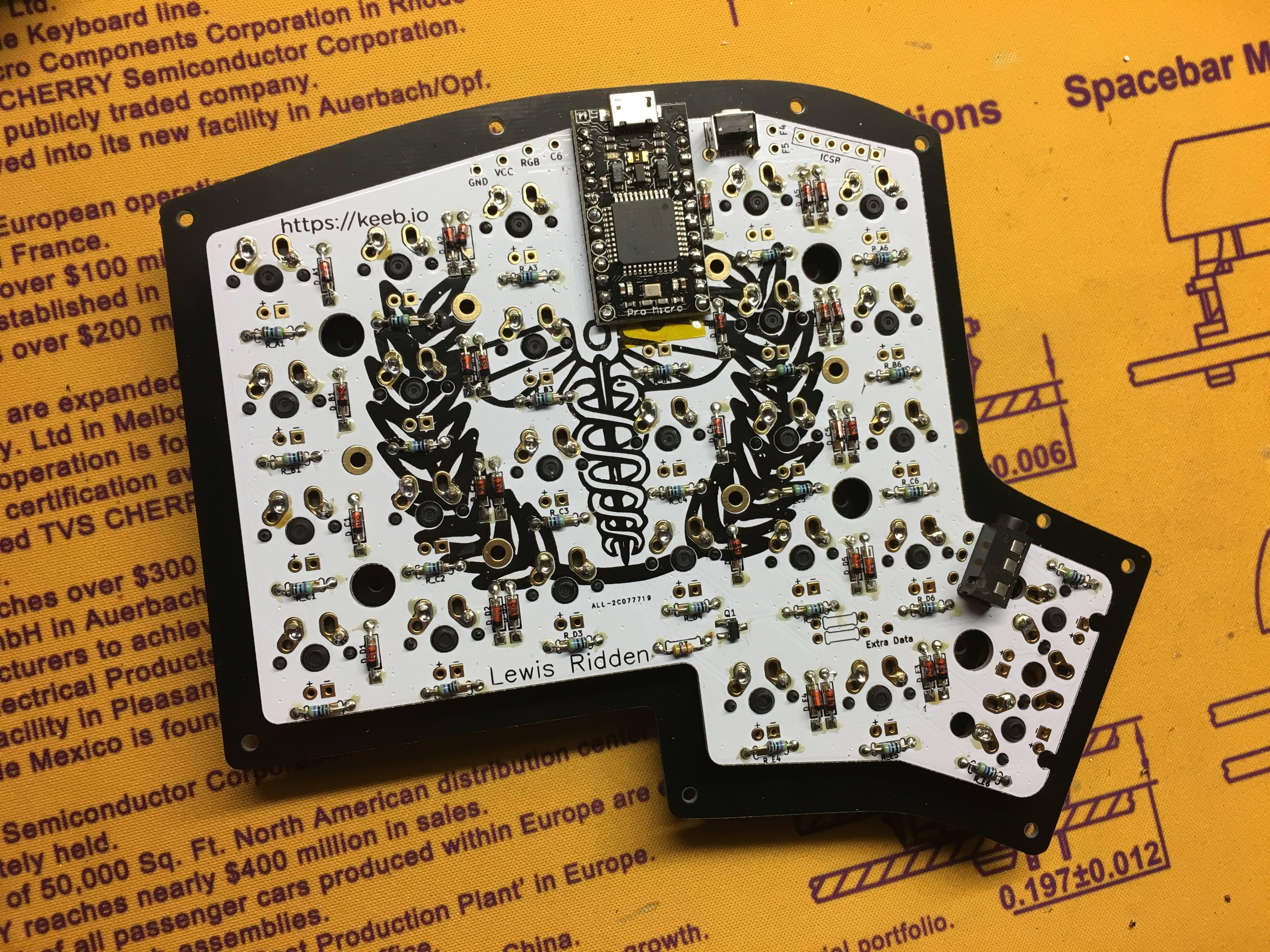
Left PCB on the left, right PCB on the right: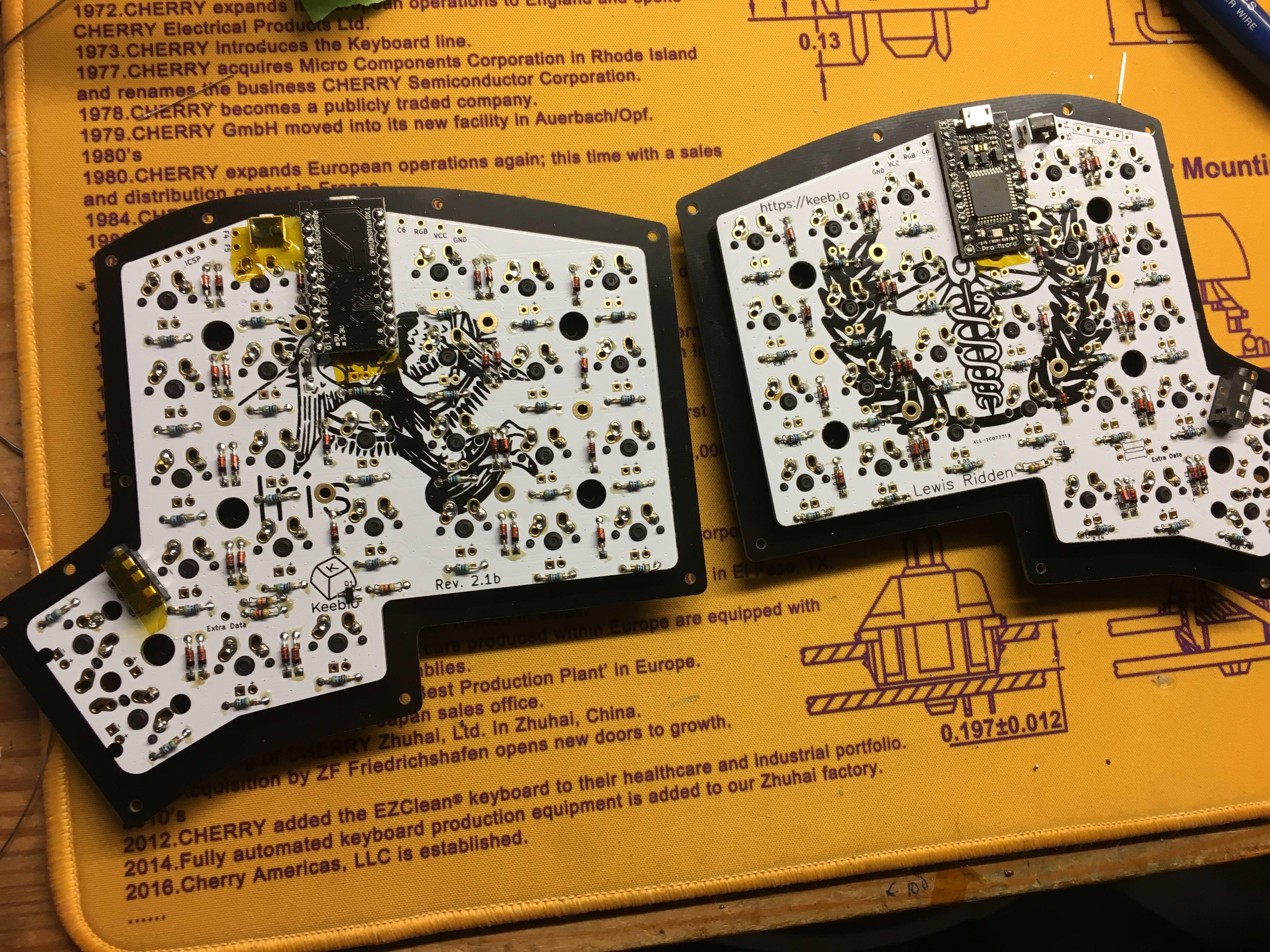
Solder RGB strip (optional)
Refer to the Adding RGB Underglow Guide for steps to install the RGB light strip.