Nyquist Rev. 1
Nyquist Rev. 2
For the Nyquist Rev. 2 PCB, see the Iris Build Guide instead, as that is more applicable. This guide covers just the Nyquist Rev. 1 PCB.
Parts List
Here's a list of parts needed for the build:
- 2 Nyquist PCBs
- 60 diodes (through-hole and SMD diodes supported)
- 2 Arduino Pro Micros
- 2 push buttons for resetting
- 60 switches (MX-compatible and Alps switches are supported)
- Case
- 2 TRRS jacks (included in kit)
- 1 TRRS cable
- Optional parts
- 2 4.7kΩ resistors if doing I2C
- 2u PCB mount MX stabilizers if using 2u keys
Build Steps
Here's a summary of the build steps:
- Solder components
- Solder diodes
- Solder resistors (optional)
- Solder push button
- Solder Pro Micro header pins
- Add 2u stabilizers
- Solder switches
- Flash Pro Micros
- Solder Pro Micros
- Solder RGB strip (optional)
Soldering the Components
Bare PCB, older version (1.1) that only has 1 2u slot, but the same as the current version otherwise: 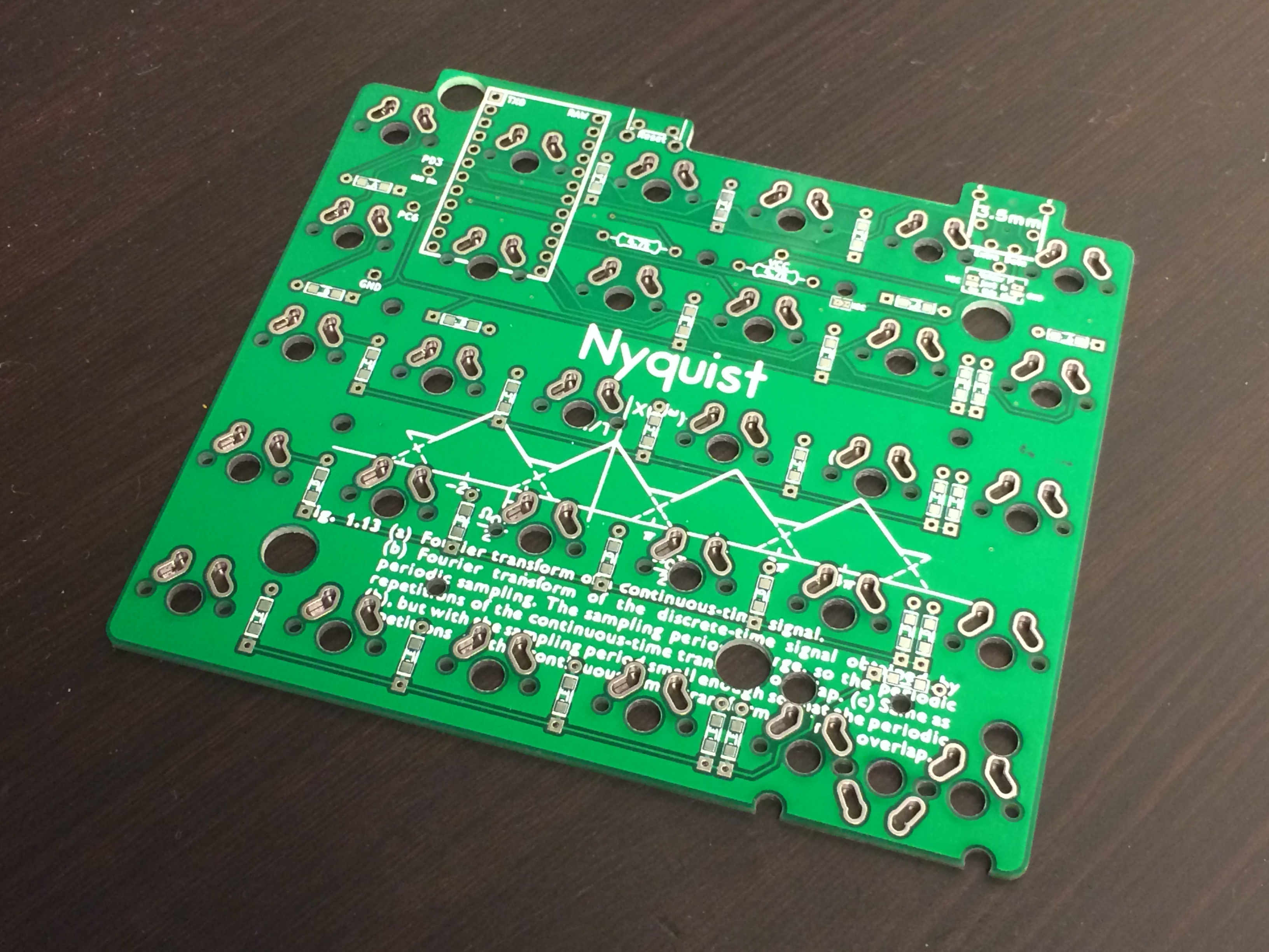
Solder on the TRRS jack, diodes, and resistors (optional). The resistors for I2C only need to be soldered on one half of the board: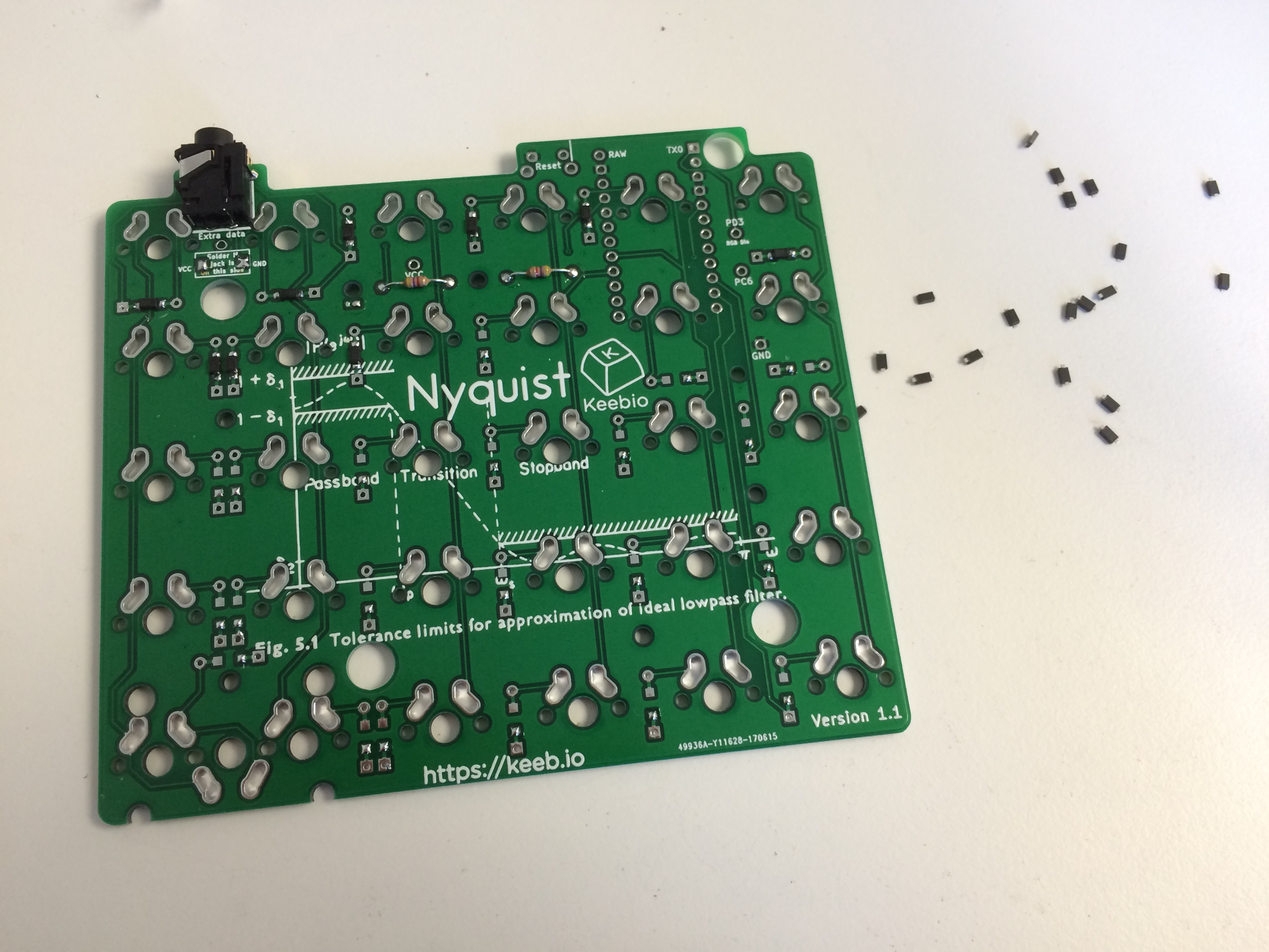
The line on the diodes should face the square pad: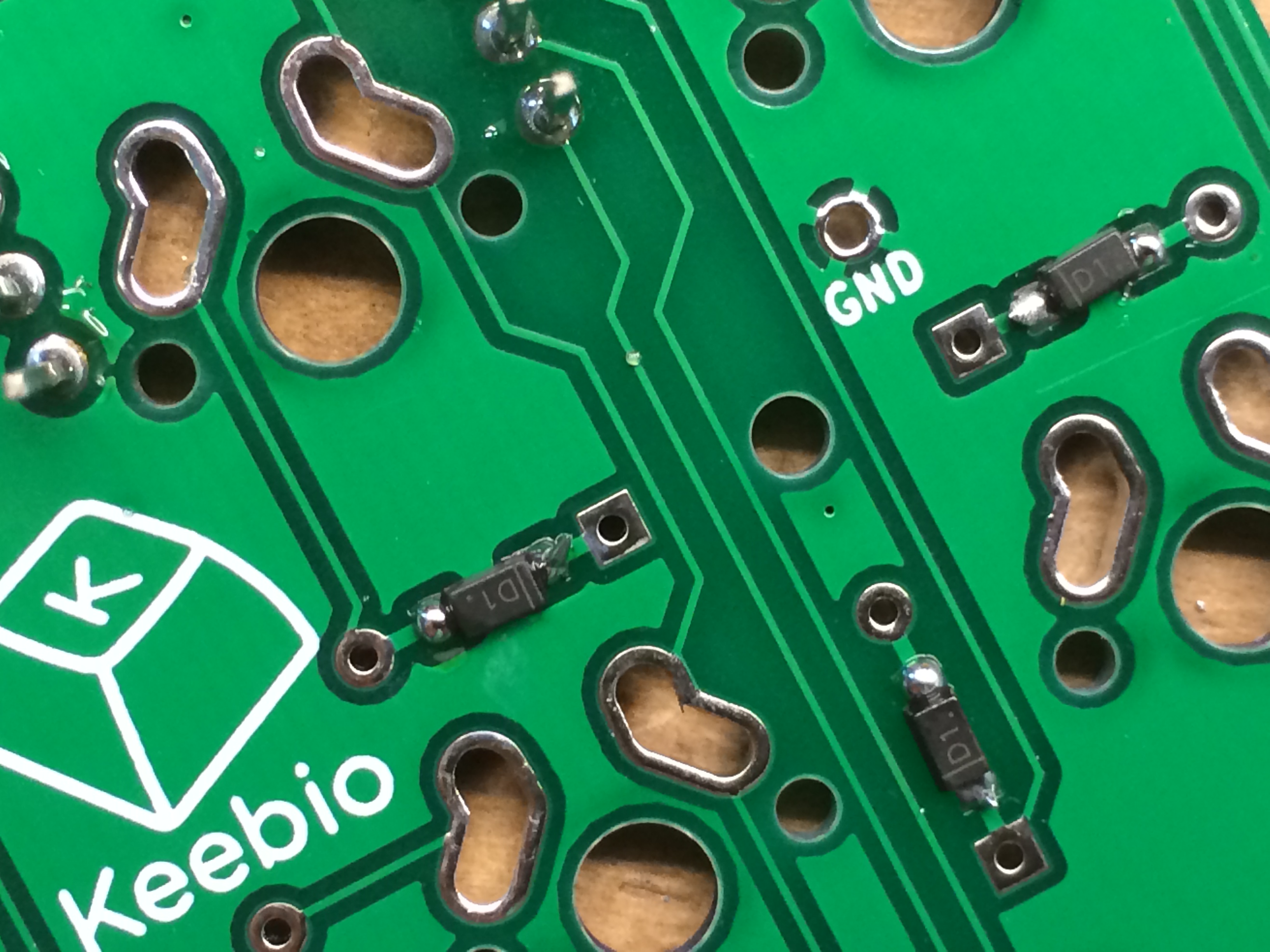
Soldering of diodes complete: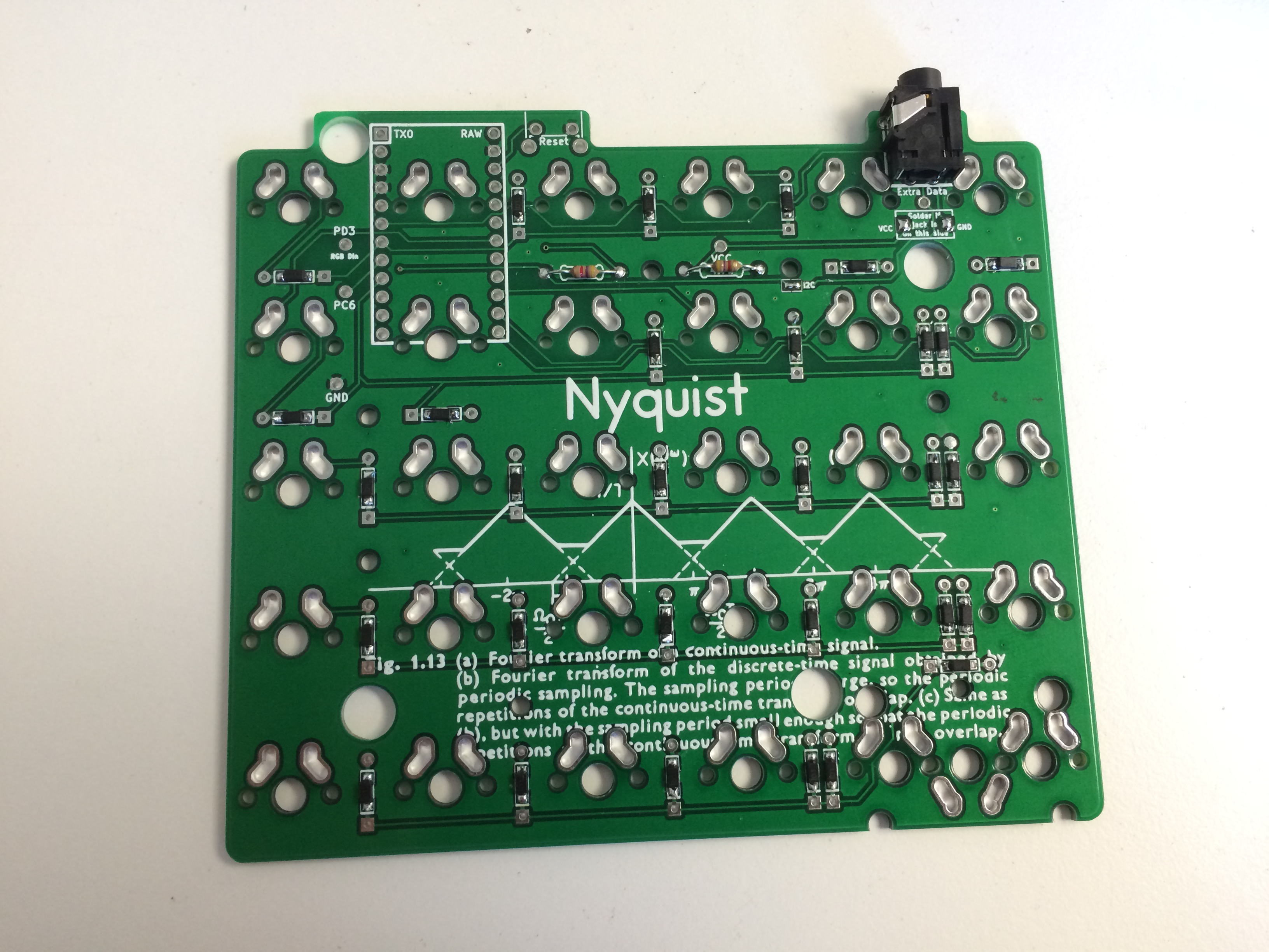
(Rev. 1.0 to 1.3 only) Solder the TRRS jumpers on the side with the jack:
Starting with Rev. 1.4, the TRRS jack has been changed to a slimmer one and the PCB has been designed to not need TRRS jumpers, making the build easier. There are no solder jumpers anymore.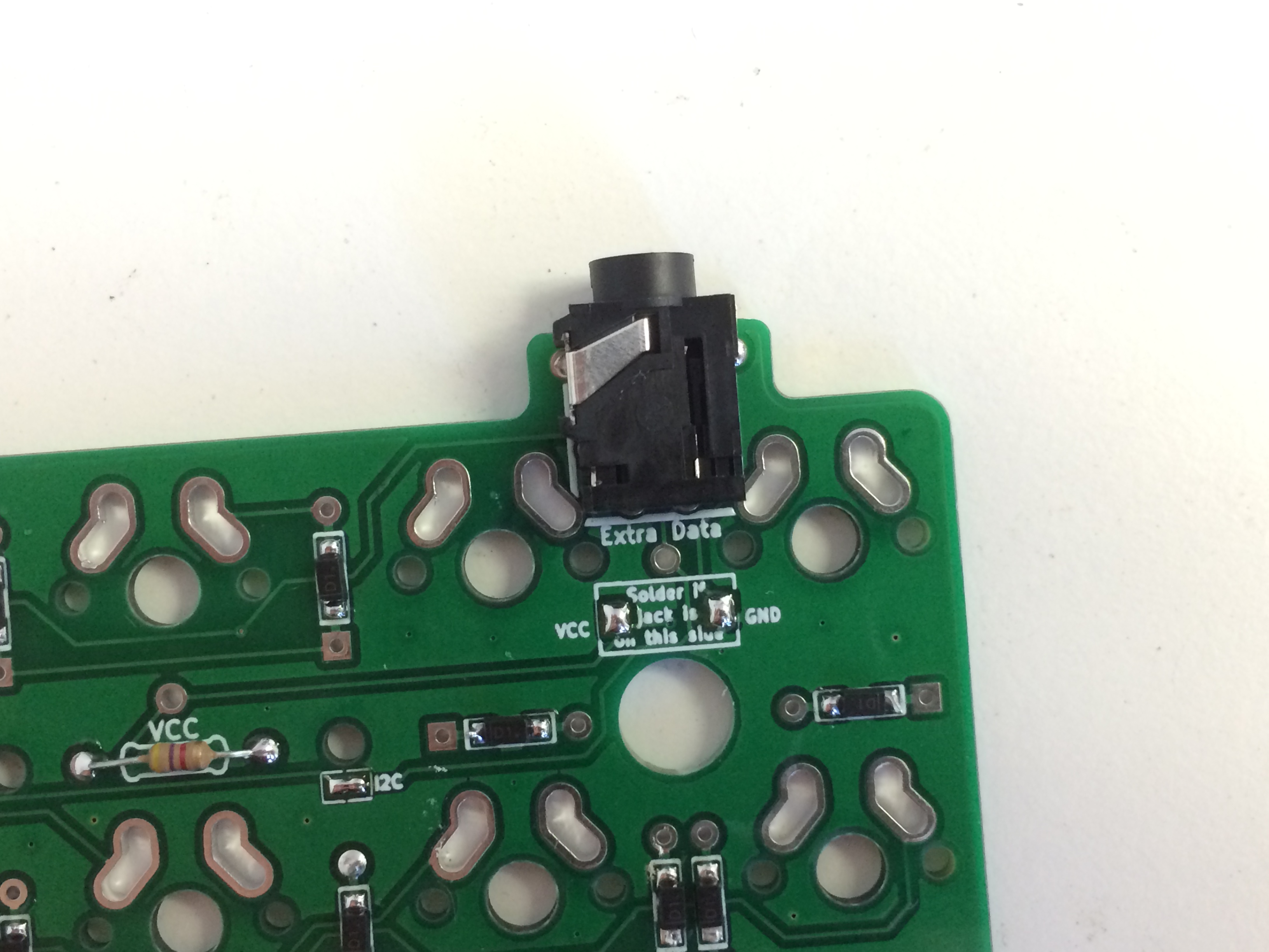
Make sure the jumpers on the side without the jack are not soldered: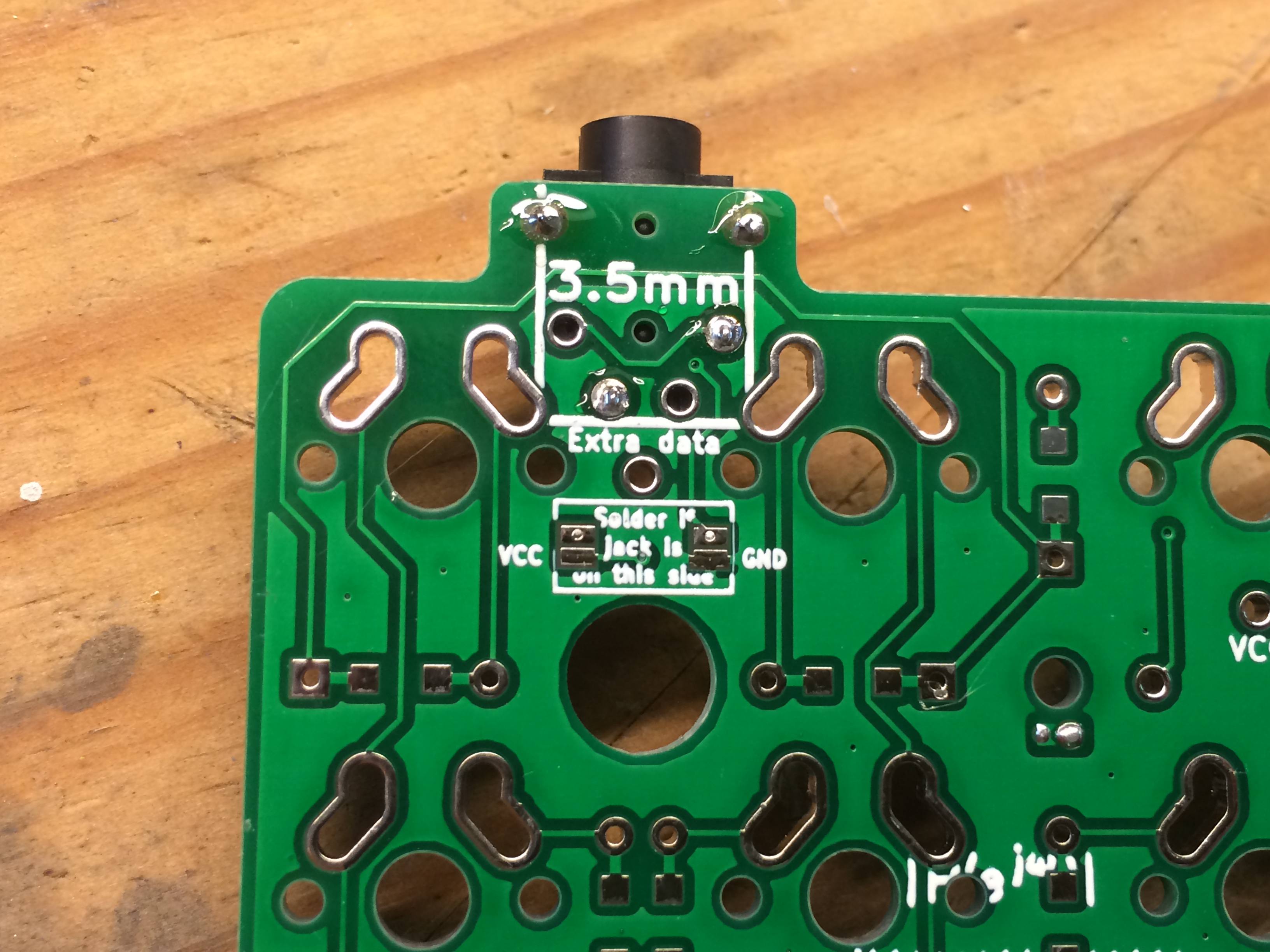
If doing I2C, solder the I2C jumper: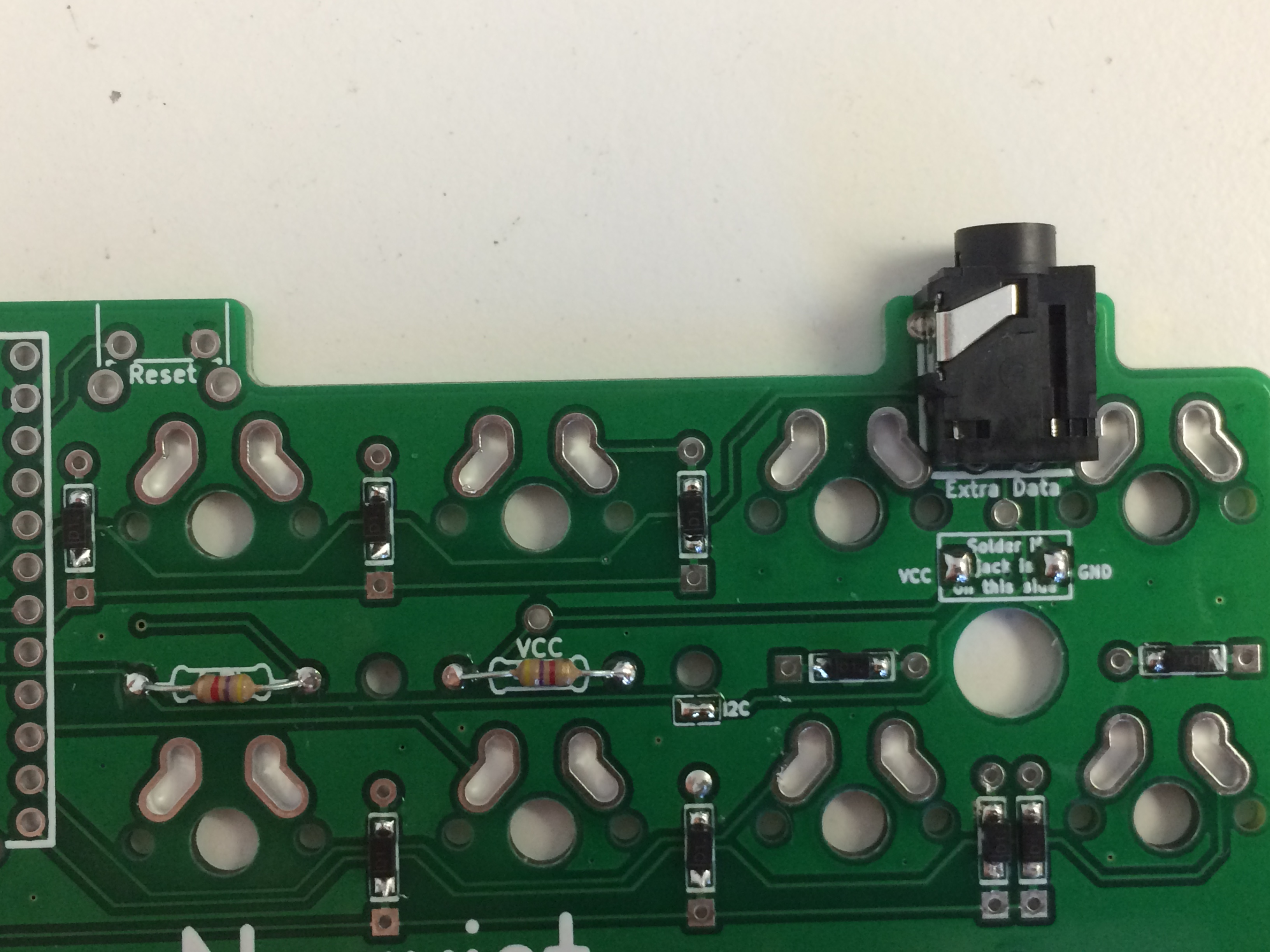
Solder in the Pro Micro header pins. The header pins are flipped upside down here to make removing the plastic a lot easier: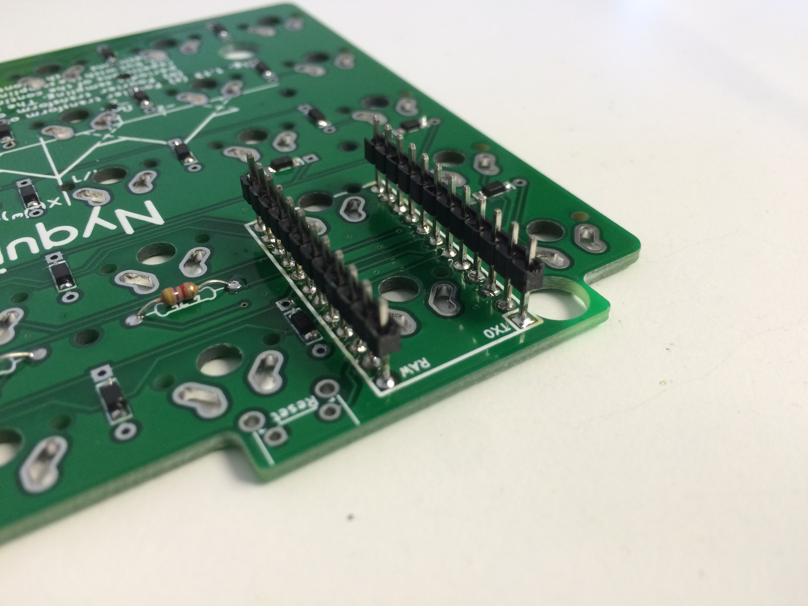
Plastic removed from the header pins to make everything as low profiles as possible: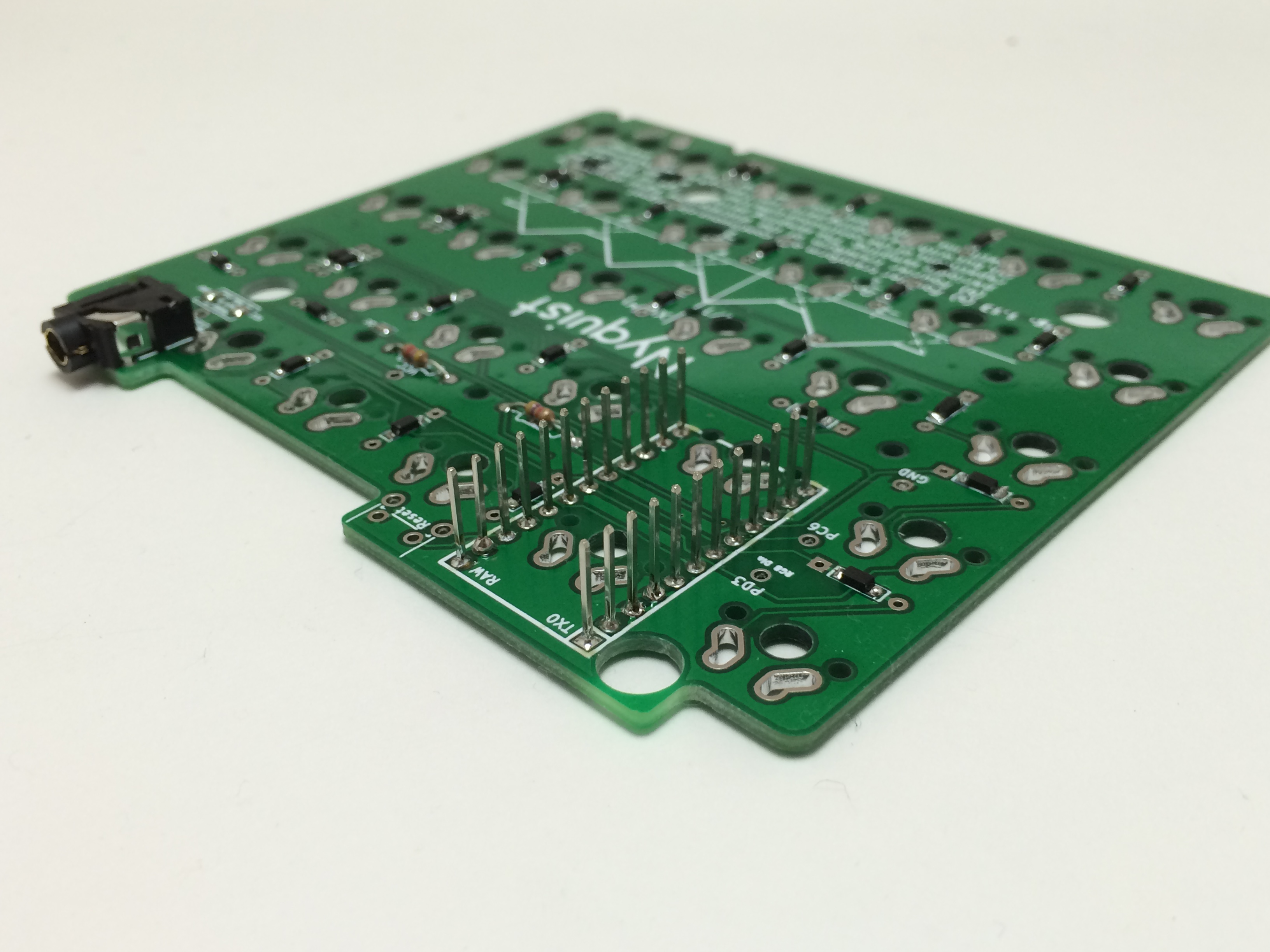
Solder on the right-angle reset pushbutton: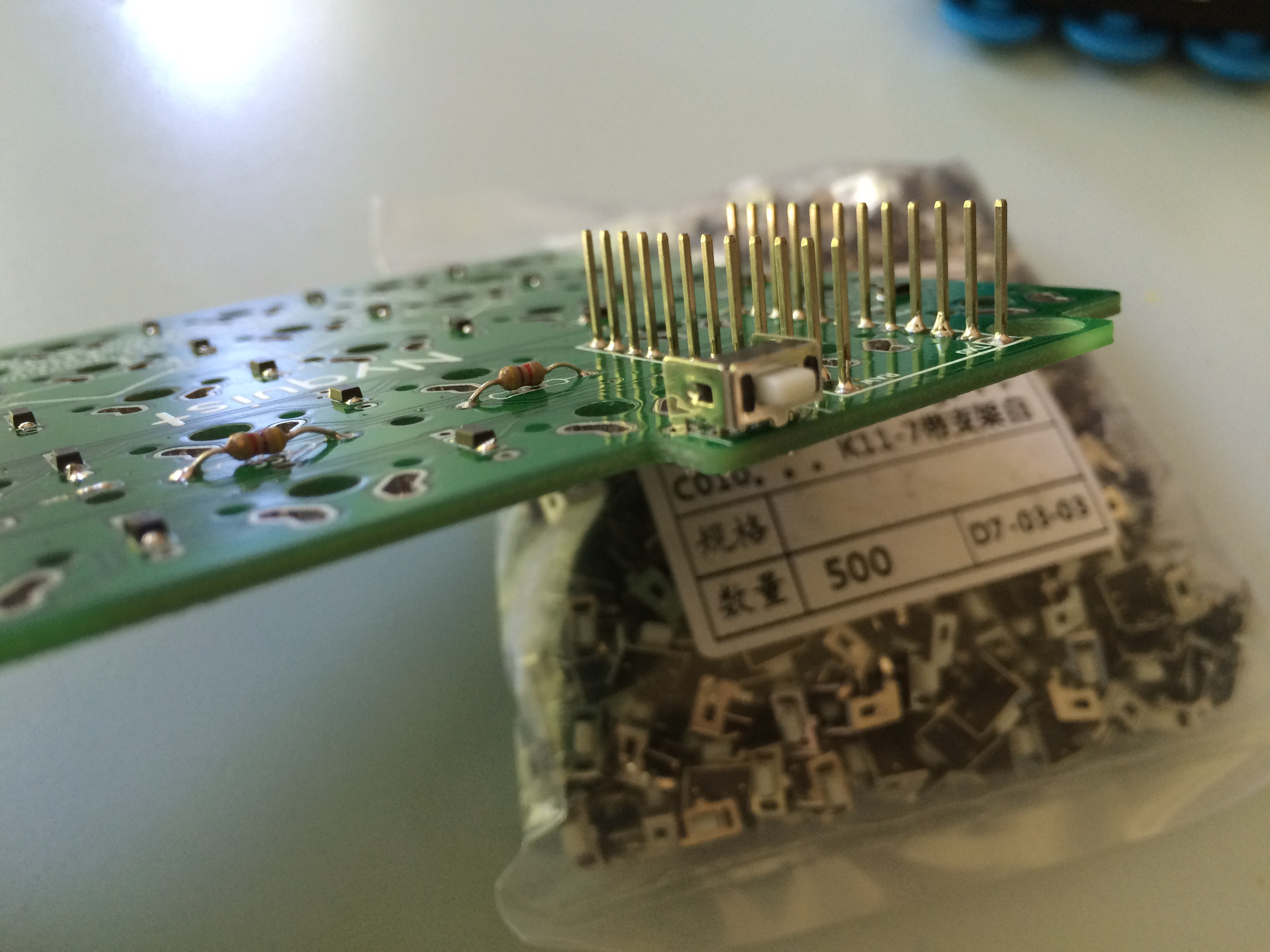
Finished halves: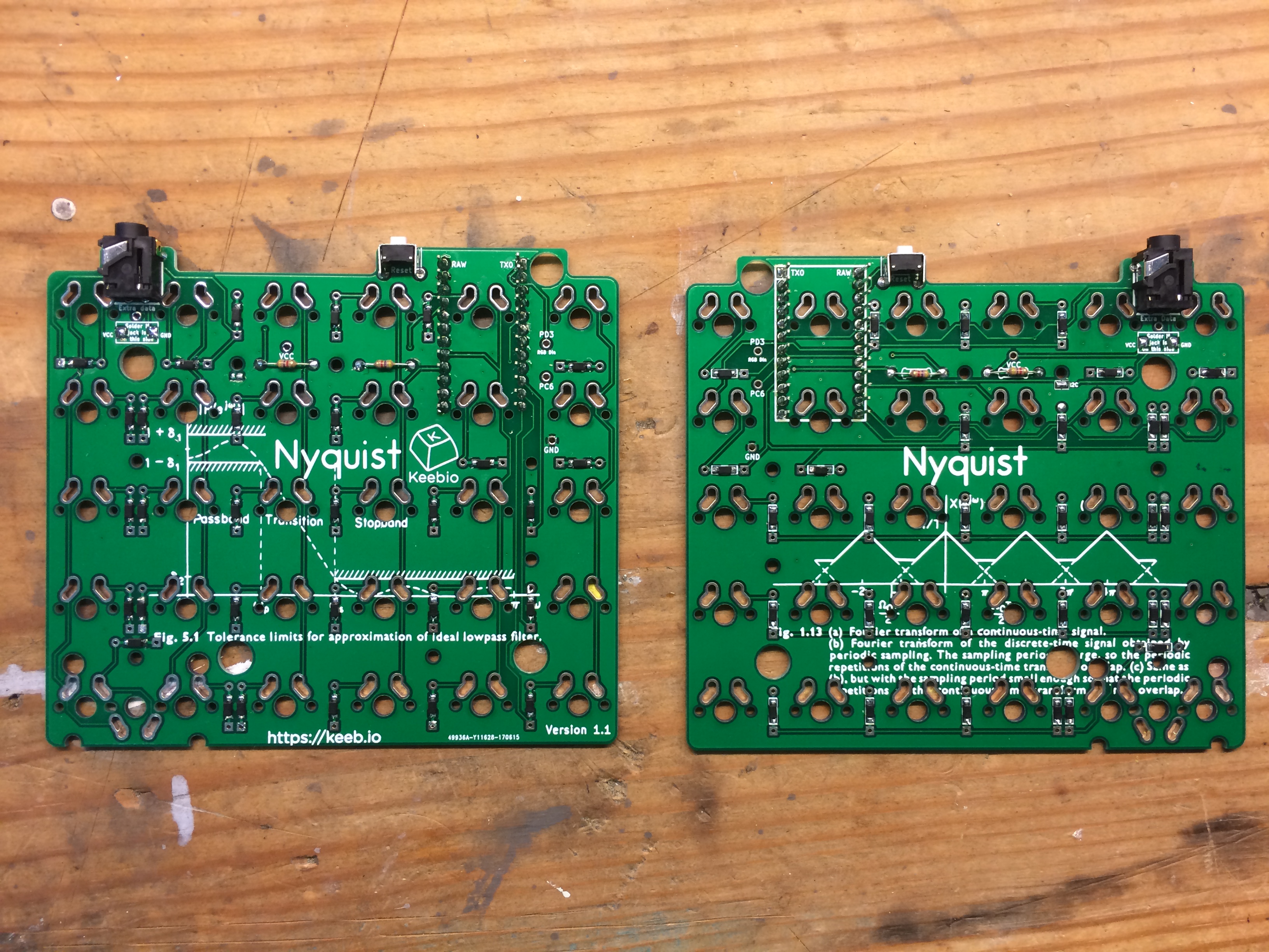
Add 2u stabilizers (optional)
If you are doing 2u keys with stabilizers, install the stabilizers now. Make sure the bottom of the stabilizer snaps into the PCB.
Add switches
Work in progress...
If using Alps switches, you will need to modify the two switches that will sit on top of the Pro Micro, since the width of the switch will touch the header pins of the Pro Micro.To modify the switches, you will have to shave off about 1-2mm on each side of the switch. (TODO: add picture here).
Add the Pro Micros (make sure you do this last!)
Work in progress...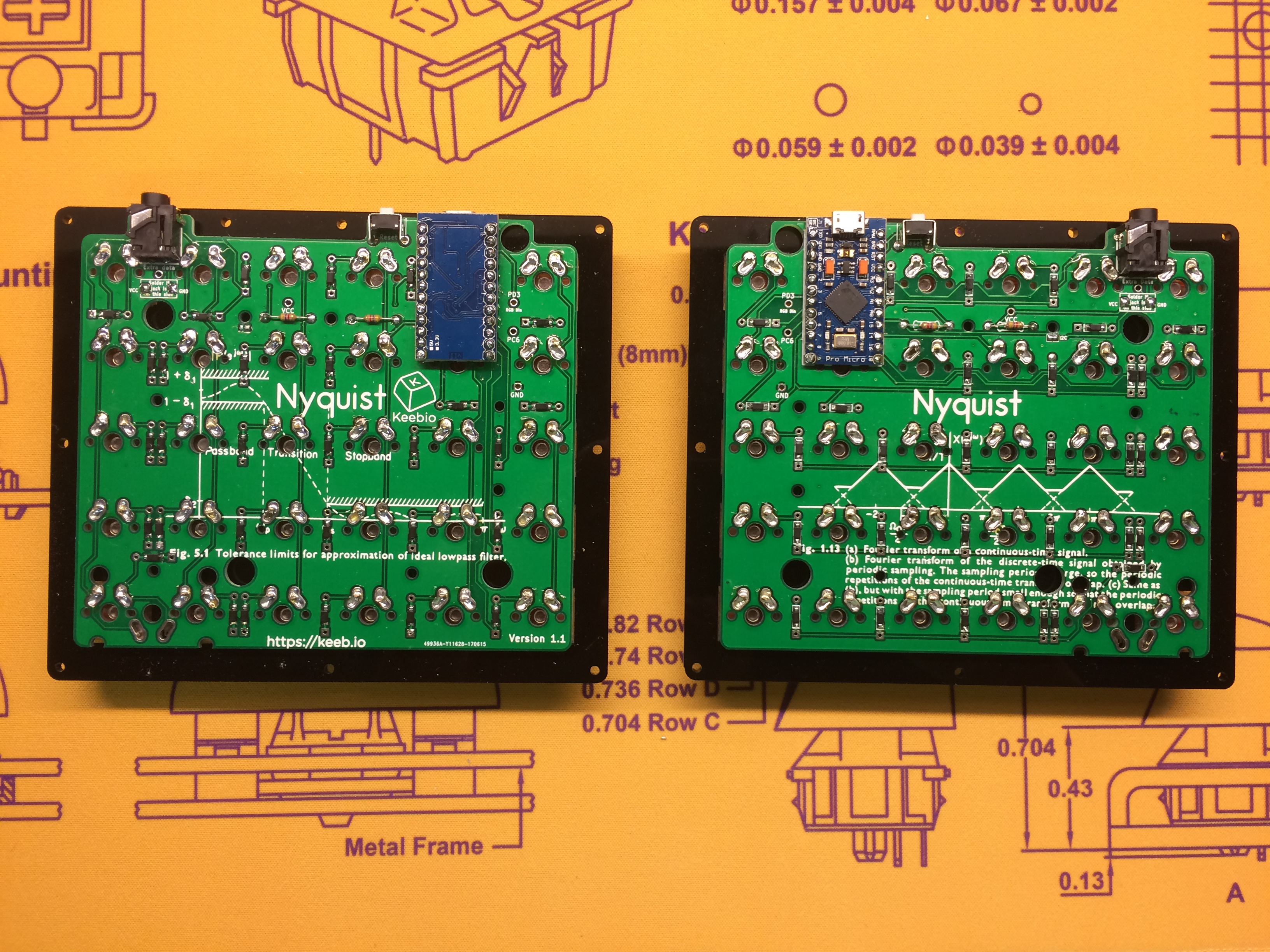
Solder RGB strip (optional)
Refer to the Adding RGB Underglow Guide for steps to install the RGB light strip.