Quefrency/Sinc/KBO-5000 (Solder Version)
Build Compatibility
This build guide is exclusively for Quefrency Rev. 2 or 3, Sinc Rev. 1 or 2, and KBO-5000 Rev. 1! They both have pre-soldered components. If you have the Quefrency Rev. 1 PCBs, see Quefrency Rev. 1 Build Guide.
Videos of Builds
Here are some cool folks who have built these keyboards! Give them a look to see how they do it.
- FrostyKoala - Prototype Quefrency Rev. 2 Build
- FrostyKoala - Prototype Sinc Rev. 1 Build
- VogonPT - Prototype Sinc Rev. 1 Build Stream
Build Tutorial Videos by Keebio
Parts List
Now you've watched some cool videos and feel inspired! Get your parts:
- PCBs:
- Plates:
- Interconnect Cable:
- TRRS cable (for boards that use TRRS, like the Quefrency Rev. 2 or Sinc Rev. 1)
- USB-C to USB-C cable (for boards that use USB-C for interconnect)
- Switches (MX-compatible ones)
- Optional parts:
- 2u PCB mount MX stabilizers if using 2u/2.25u/2.75u keys
- Rotary Encoder and Knob
Build Steps Summary
- Prepare components
- Break off PCB sections
- Add 2u stabilizers to PCB
- Add switches
- Optional Stuff!
- Solder rotary encoder (optional)
- Solder in-switch LEDs (optional)
- Note: For Kalih Box switches, LEDs must be installed before the switches.
- Assemble!
- Insert standoffs into middle layer (optional)
- Screw standoffs into switch plate
- Attach bottom plate using screws
- Re-Programing Board Note
- Rejoice!
Prepare Components
Have your soldering iron, solder, and if you feel accident prone with your soldering (It's okay! Happens to the best of us!), a solder sucker. See Recommended Soldering Tools if you need some recommendations.
Some individuals may want to lubricate their switches. If you'd like to, go ahead and do that now before starting the process. For further details on that, go here.
Get a playlist of some jams you like and get started!
Break Off PCB Sections
If you're going to go with a layout without the left macro section or right macro column, then break off those portions of the PCB. No special tools or methods are required, you can just break it off with your hands as shown below:
Add 2u stabilizers to PCB
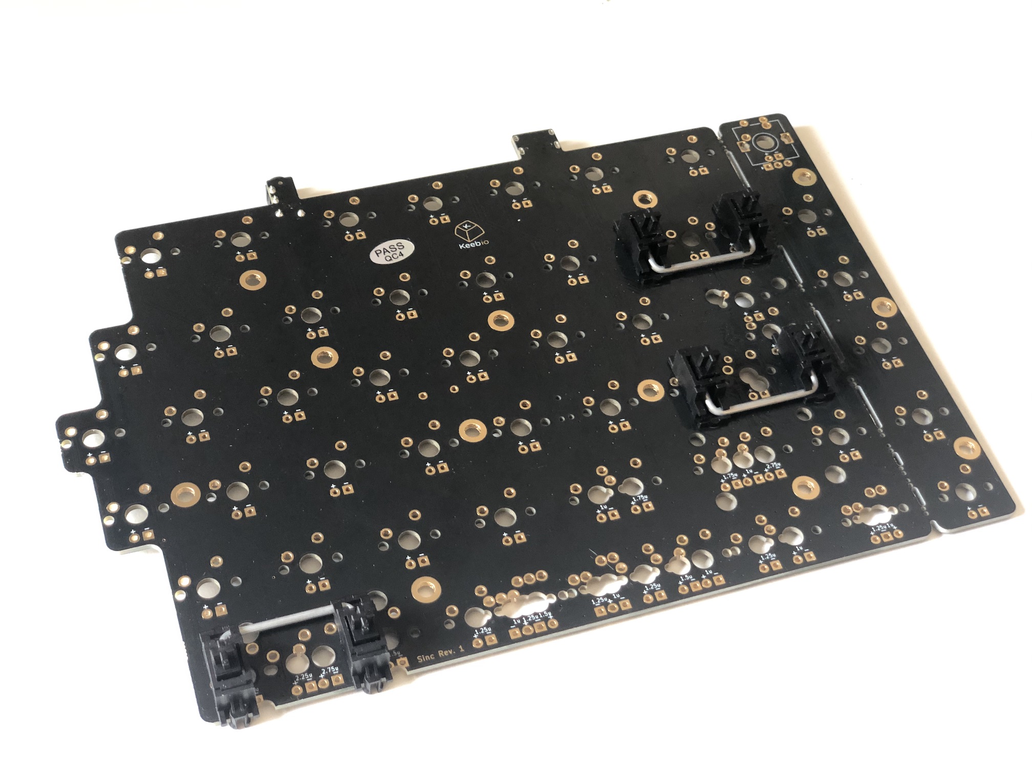
Add the 2u stabilizers into the PCB. The stab wire will be on the bottom side of the switch for everywhere except for the bottom row. On the bottom row, the stab wire will be above the switch. Do this before installing the switch plate and switches, as stabilizers can not be removed after the switches have been soldered in.
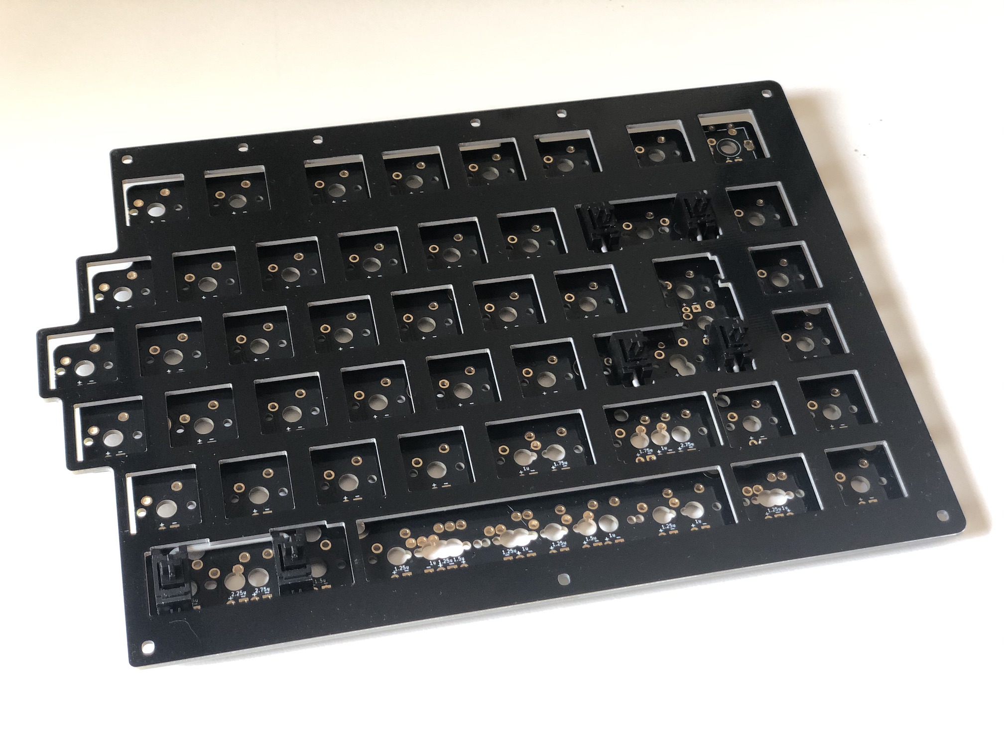
Afterwards, fit the plate over the stabilizer(s).
Add Switches
Now on to the exciting part: putting the switches in the switch plate and solder.
There is no cutout to insert in-switch LEDs, so the LEDs must be added first. If you're adding LEDs, first do the LED installation step and then come back to this step of switch installation.
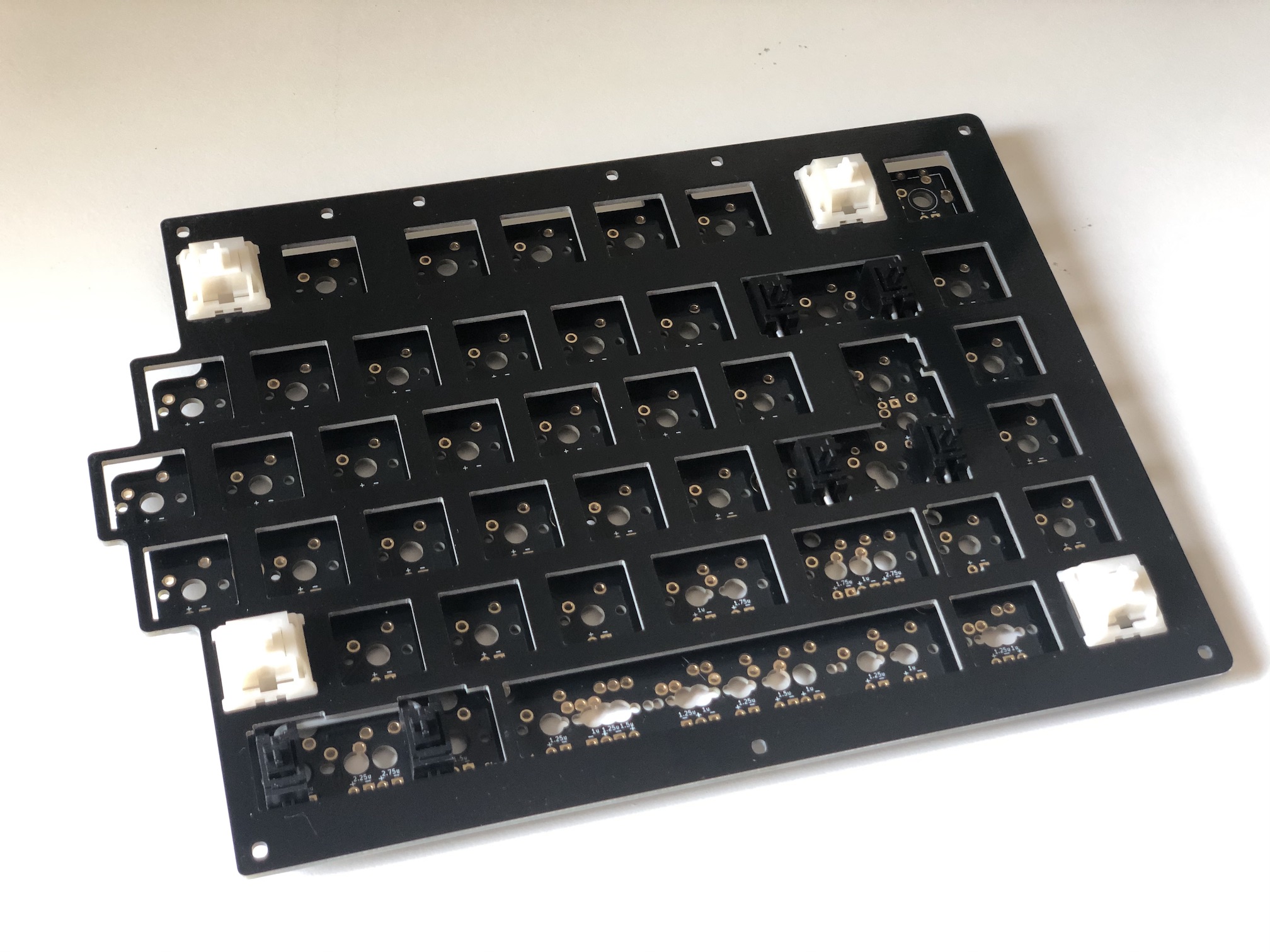
Add switches into the switch plate. It's a good idea to add switches to the corners first and then solder them before installing the rest of them:
Solder the switches onto the PCB.
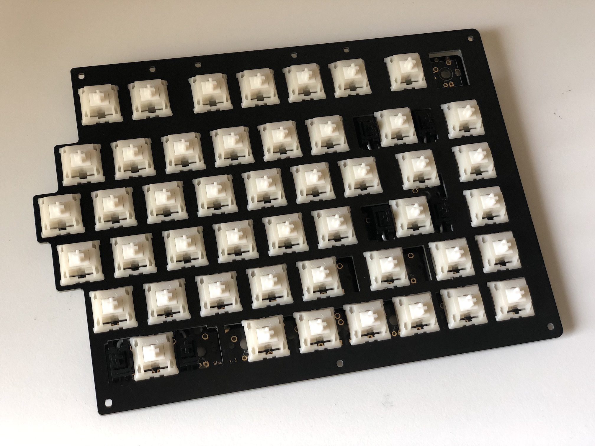
Add the rest of the switches and solder them.
Optional Stuff!
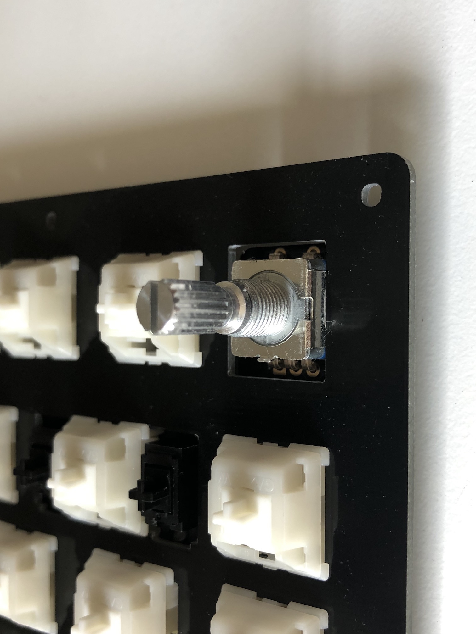
Solder Rotary Encoder
This step can be done after installing the switches. For the prototype plates, the encoders had to be installed first, but for the plates available on the store, the switch cutouts are now large enough to allow the encoders to be installed later.
Install the encoder onto the PCB and solder the 2 pins at the top side of the encoder and the 3 pins at the bottom side. The 2 side legs do not need to be soldered to the PCB.
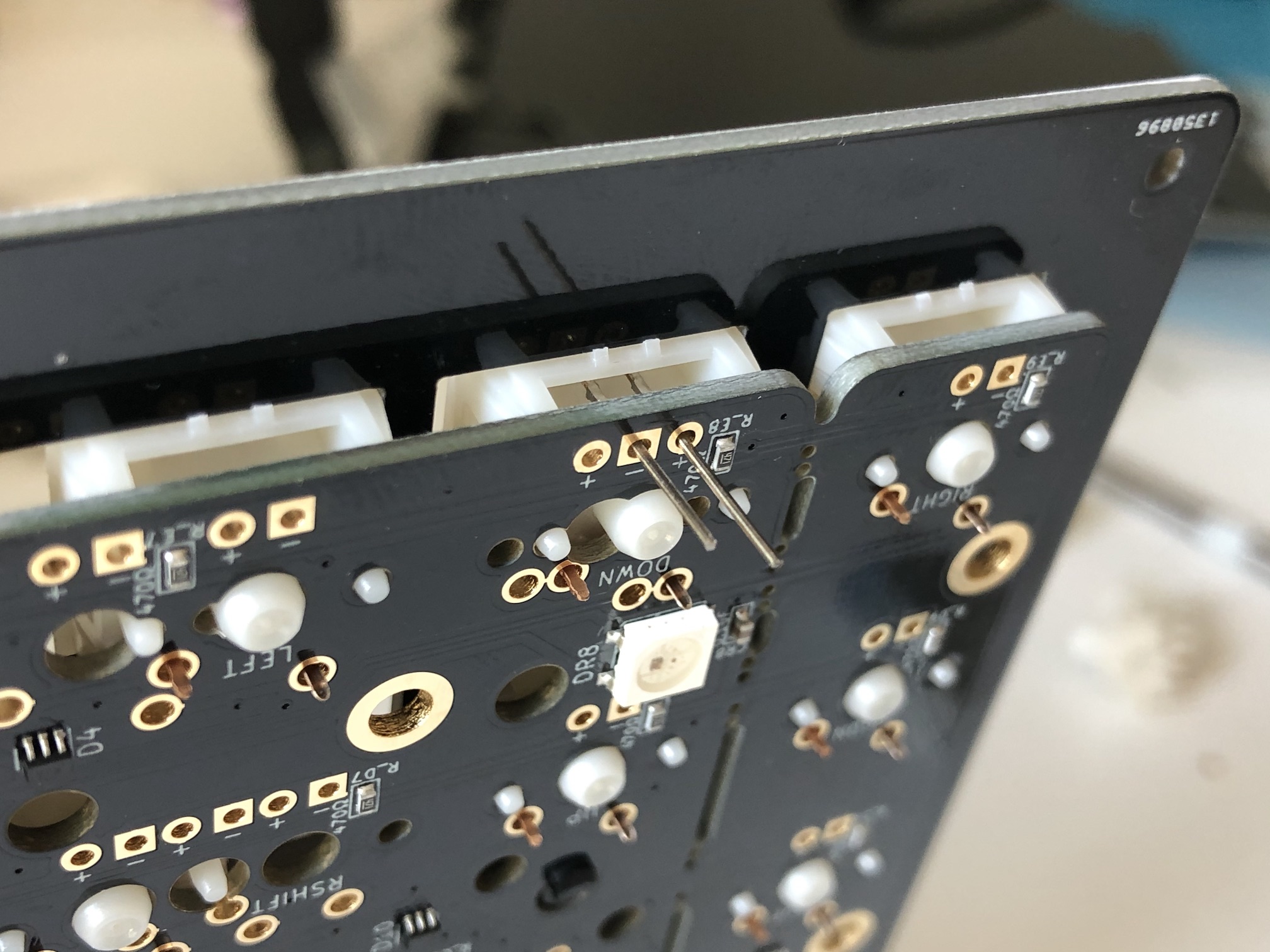
Solder in-switch LEDs
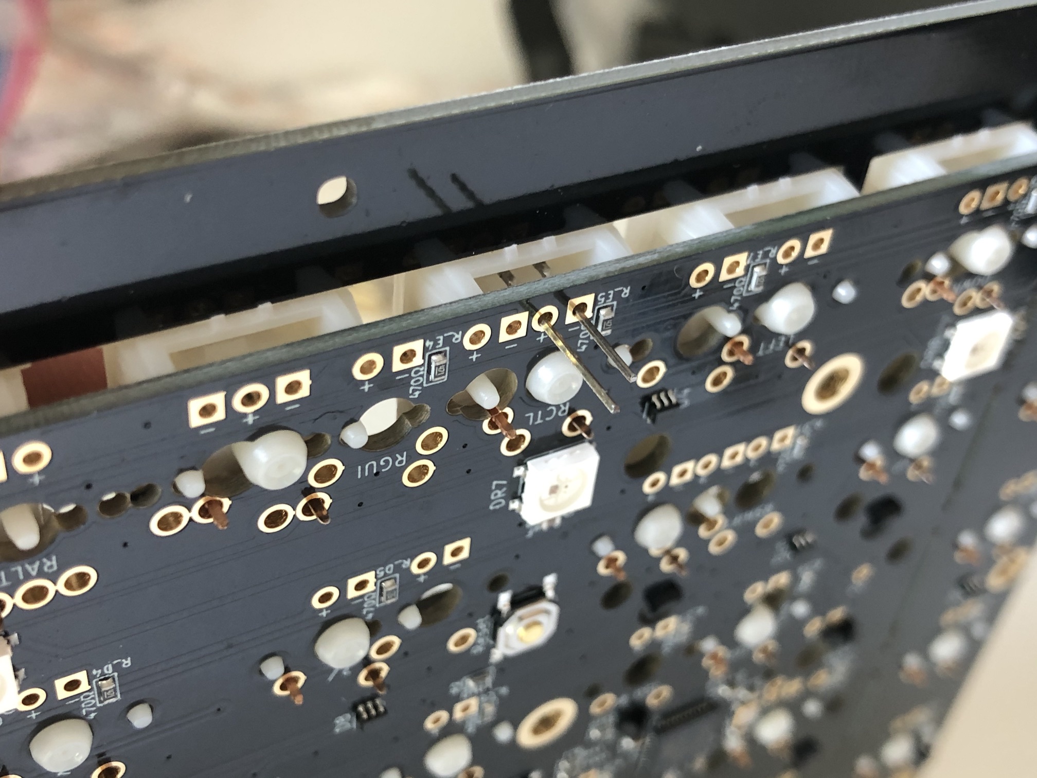
Polarity of the in-switch LEDs is important. Match up the longer leg of the LED to the + sign of the LED pins on the PCB. The shorter leg will match the - sign.
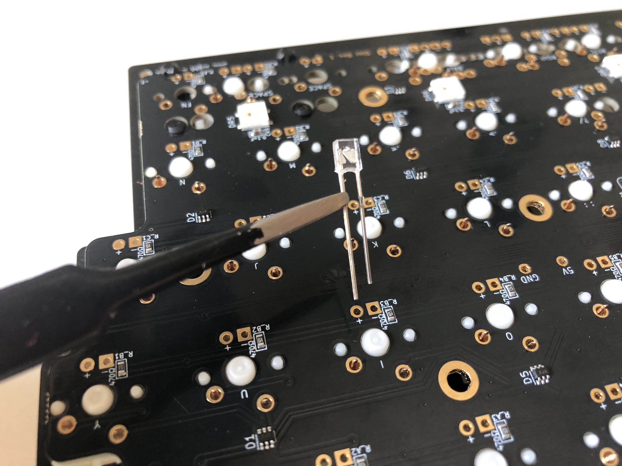
Insert the LED through the switch and PCB:
Bend the LED legs out so it doesn't fall out while soldering the LED in:
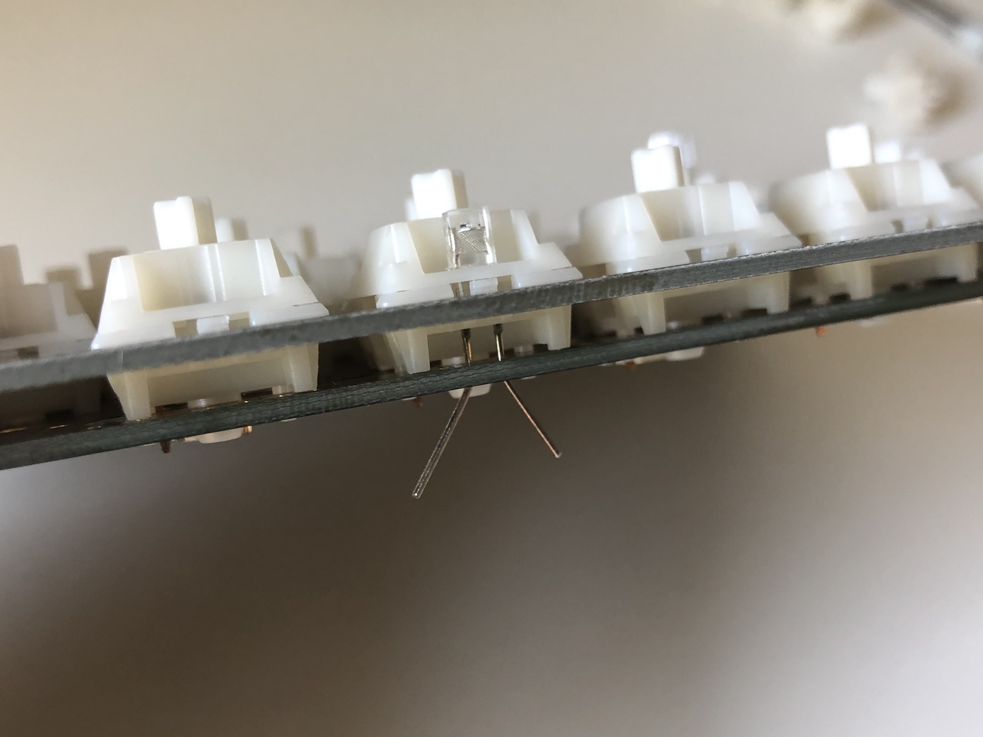
Solder the LED legs and then clip the excess length on the legs. Be careful to not damage the resistor next to the LED pads.
Note that some of the switch layout options have the -/+ markings swapped, so make sure to always put the longer leg through the + pad. If you are unsure, plug the PCB in and test the LED before soldering it in.
Assemble!
If you are installing 3D-Printed pieces around the FR4 plates, then please see these instructions instead: 3D-Printed Case Parts Installation
Insert a screw through the top of the switch plate and attach a standoff from the bottom side of the plate:
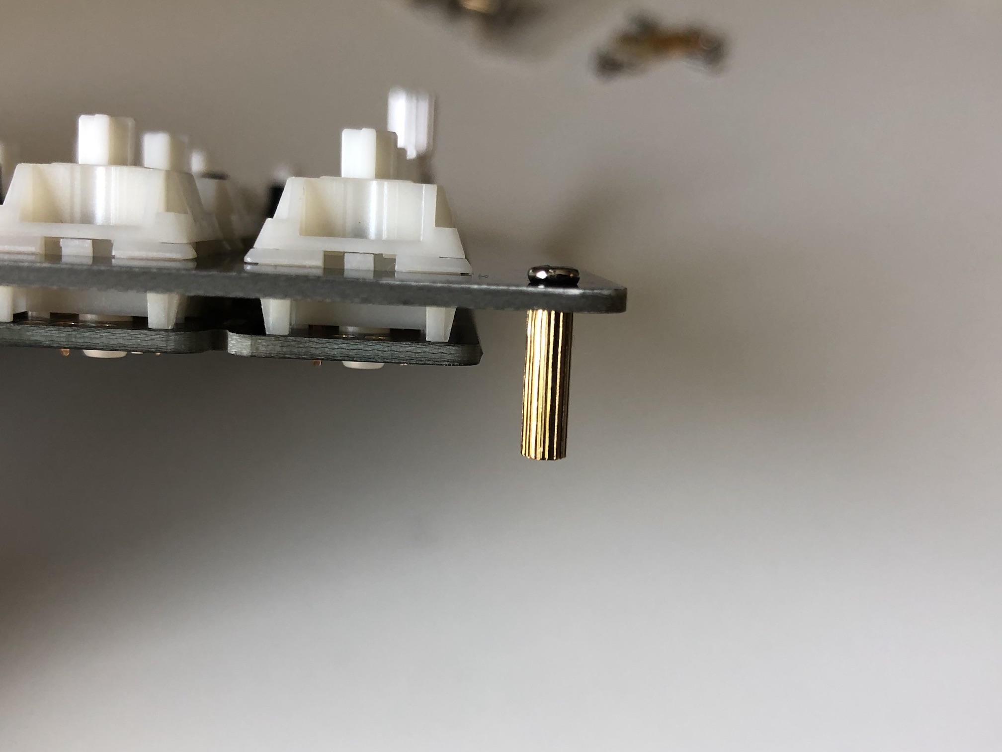
Repeat the process for the rest of the plate.
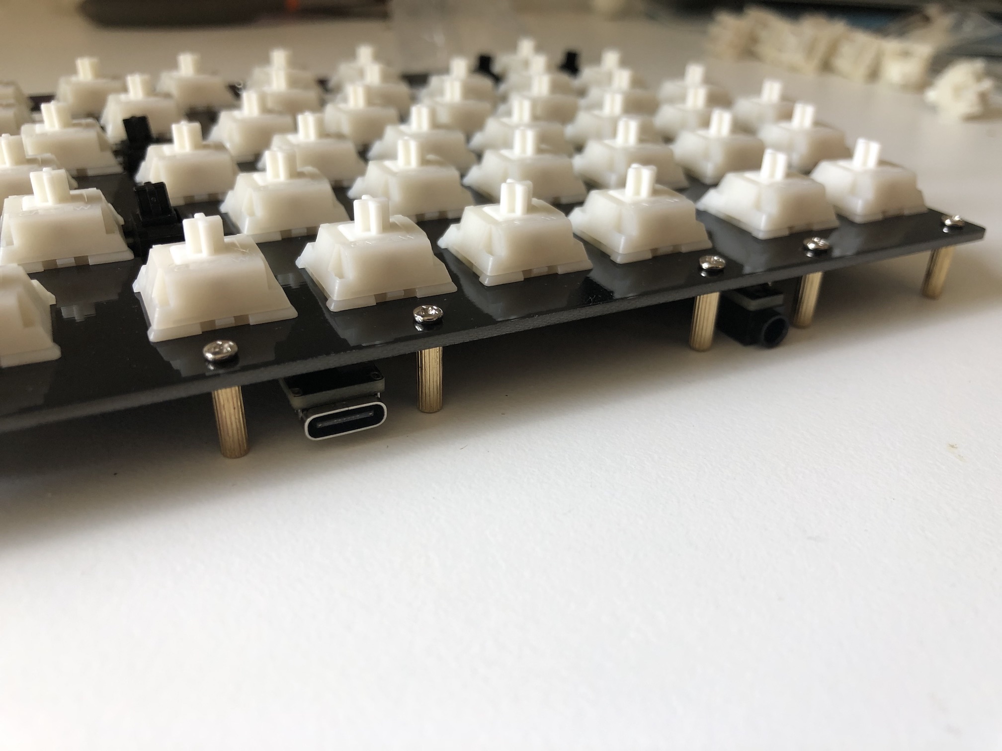
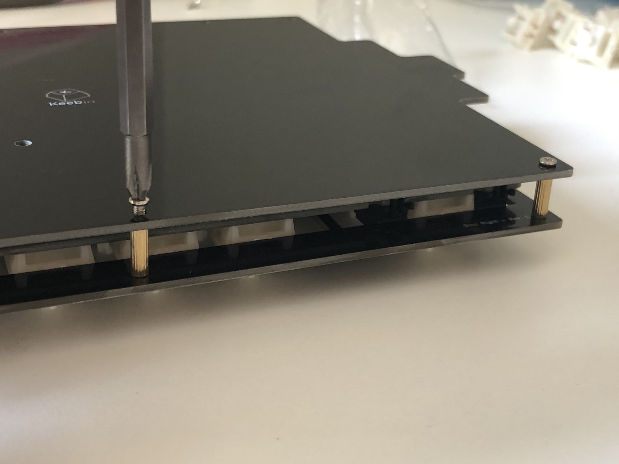
If you have a middle layer, now is the time to insert it around the standoffs.
Put bottom plate on and add screws:
Re-Programming Board Note
Oh, looking to re-program your board? Never fear! Come look here.
Rejoice!
You have a keyboard! Savor this moment of victorious keyboard construction.